1995 JEEP YJ engine coolant
[x] Cancel search: engine coolantPage 1126 of 2158
switch to ground on circuit Z1. The switch closes dur-
ing periods of high power steering pump load and
low engine speed; such as parking maneuvers. Cir-
cuit K10 connects to cavity 10 of the PCM.
TACHOMETER SIGNAL
The Powertrain Control Module (PCM) supplies the
signal for the tachometer on circuit G21. Circuit G21
connects to cavity 43 of the PCM.
MALFUNCTION INDICATOR LAMP (MIL)
The Powertrain Control Module (PCM) provides
ground for the instrument cluster malfunction indica-
tor lamp on circuit G3. The MIL displays the mes-
sage CHECK ENGINE when illuminated. Circuit G5
provides voltage for the lamp.
DATA LINK CONNECTOR
Circuit G50 supplies battery voltage to the data
link connector. Circuit G50 originates at fuse 5 in the
fuse block. Circuit G50 is double crimped at the data
link connector and connects to cavity 9 of the Power-
train Control Module (PCM).
Circuit A21 from the ignition switch powers fuse 5
when the switch is in the START or RUN positions.
In the START or RUN position the ignition switch
connects circuit A1 from fuse 4 in the Power Distri-
bution Center (PDC) with circuit A21.
Circuit D20 connects to cavity 45 of the PCM. Cir-
cuit D20 is the SCI receive circuit for the PCM.
Circuit D21 connects to cavity 25 of the PCM. Cir-
cuit D21 is the SCI transmit circuit for the PCM.
Circuit Z11 provides ground for the data link con-
nector. Circuit Z11 splices to circuit Z1 which termi-
nates at the right rear of the engine. Circuit Z11 also
connects to cavity 5 of the PCM.
HELPFUL INFORMATION
²Circuit Z1 also supplies a ground for the PCM
high current drivers.
²If the system loses ground for the Z1 and Z11 cir-
cuits at the right rear of the engine, the vehicle will
not operate. Check the connection at the ganged-
ground circuit eyelet.
BRAKE SWITCH INPUT
Circuit V40 provides the brake switch input to the
Powertrain Control Module (PCM). Circuit V40 con-
nects to cavity 29 of the PCM.
POWER (DEVICE) GROUND
Circuit Z11 connects to cavities 11 and 12 of the
Powertrain Control Module (PCM). The Z1 circuit
provides ground for PCM internal drivers that oper-
ate high current devices like the injectors and igni-
tion coil.
Internal to the PCM, the power (device) ground cir-
cuit connects to the PCM sensor return circuit (from
circuit K4).
HELPFUL INFORMATION
²The grounding point for circuit Z1 is the right rear
of the engine.
²If the system loses ground for the Z1 circuits at
the rear of the engine, the vehicle will not operate.
Check the connection at the ganged-ground circuit
eyelet.
DIAGRAM INDEX
Component Page
Automatic Shut Down Relay...............8W-30-6, 14
Camshaft Position Sensor................8W-30-10, 16
Crankshaft Position Sensor...............8W-30-10, 16
Data Link Connector...................8W-30-11, 17
Daytime Running Lamps (DRL) Module.......8W-30-11, 17
Engine Coolant Temperature Sensor..........8W-30-9, 18
Fuel Pump Relay........................8W-30-20
Fuel Tank Level Unit......................8W-30-21
Fuse 1 (PDC)........................8W-30-6, 14
Fuse 4 (PDC)........................8W-30-6, 14
Fuse 5 (Fuse Block).................8W-30-6, 14, 20
Heated Oxygen Sensor..................8W-30-7, 15
Idle Air Control Motor..................8W-30-12, 18
Ignition Switch.....................8W-30-6, 14, 20
Ignition Coil........................8W-30-12, 18
Injectors (4.0L).........................8W-30-13
Injectors (2.5L)..........................8W-30-8
Instrument Cluster....................8W-30-11, 17
Intake Air Temperature Sensor.............8W-30-9, 18
MAP Sensor.........................8W-30-9, 18
Power Steering Pressure Switch..............8W-30-12
Powertrain Control Module.............8W-30-6 thru 21
Throttle Position Sensor.................8W-30-9, 18
Vehicle Speed Sensor..................8W-30-11, 17
J8W-30 FUEL/IGNITIONÐYJ VEHICLES 8W - 30 - 5
Page 1154 of 2158
INSTRUMENT CLUSTER
INSTRUMENT CLUSTER
The instrument cluster contains the gauges and
warning lamps. All gauges have magnetic move-
ments.
When the ignition switch is in either the START or
RUN position, circuit A1 from fuse 4 in the Power
Distribution Center (PDC) connects to circuit A21.
Circuit A21 powers fuse 9 in the fuse block. Fuse 9
powers circuit G5. One branch of circuit G5 connects
directly to the combination buzzer. The other branch
of circuit G5 splices to power the gauges, speedome-
ter, tachometer, voltmeter, indicator lamps, and
warning lamps in the instrument cluster.
When the parking lamps or headlamps are ON, the
headlamp switch connects circuit F33 to circuit L7.
Circuit L7 splices to the dimmer switch. Circuit E1
from the dimmer switch powers fuse 10 in the fuse
block when the parking lamps or headlamps are ON.
Circuit E2 from fuse 10 in the fuse block feeds the
illumination lamps in the instrument cluster.
Circuit Z1 provides ground the instrument cluster
illumination lamps, gauges and warning lamps.
HELPFUL INFORMATION
²Circuit G5 also powers the heated rear window,
A/C compressor clutch relay. On Canadian vehicles,
circuit G5 powers the Daytime Running Lamps
(DRL) module.
²Circuit F33 originates at fuse 8 in the fuse block.
Circuit A6 from fuse 3 in the PDC powers fuse 8 in
the fuse block.
ENGINE COOLANT TEMPERATURE GAUGE
Circuit G20 connects the engine coolant tempera-
ture gauge to the engine coolant temperature sensor.
The sensor is a variable resistor and case grounded
to the engine. Circuit G5 connects to the instrument
cluster and supplies voltage for the gauge.
The gauge uses two coils. The first coil has fixed
current flowing through it to maintain magnetic field
strength. Circuit Z1 provides ground for the fixed
current coil. The current level passing through the
second coil is controlled by the variable resistor in
the engine coolant temperature sender. The changing
current varies the magnetic field in the second coil.
Refer to group 8E, Instrument Panel and Gauges
for gauge operation.
FUEL GAUGE
Circuit G4 connects the fuel level sensor to the fuel
gauge in the instrument cluster. Circuit G5 supplies
voltage to the fuel gauge. The fuel level sensor draws
voltage from circuit G5 through the fuel gauge on cir-
cuit G4.The gauge uses two coils. The first coil has fixed
current flowing through it to maintain magnetic field
strength. Circuit Z1 provides ground for the fixed
current coil. The current level passing through the
second coil is controlled by the variable resistor in
the fuel level sensor. The changing current varies the
magnetic field in the second coil.
Circuit Z2 provides the ground path for the fuel
level sensor.
Refer to group 8E, Instrument Panel and Gauges
for gauge operation.
OIL PRESSURE GAUGE
The case grounded oil pressure sending unit is a
variable resistor. The sending unit connects to the oil
pressure gauge on circuit G60.
Circuit G5 connects to the instrument cluster and
supplies battery voltage to the oil pressure gauge.
The gauge uses two coils. The first coil has fixed cur-
rent flowing through it to maintain magnetic field
strength. Circuit Z1 provides ground for the fixed
current coil. The current level passing through the
second coil is controlled by the variable resistor in
the oil pressure sending unit. The changing current
varies the magnetic field in the second coil.
Refer to group 8E, Instrument Panel and Gauges
for gauge operation.
TACHOMETER
The Powertrain Control Module (PCM) provides
the tachometer signal to the electronic tachometer on
circuit G21. Circuit G21 originates at cavity 43 of the
PCM. Circuit Z1 provides ground for the tachometer's
internal logic circuits.
SPEEDOMETER
The electronic speedometer and odometer receive a
signal from the vehicle speed sensor on circuit G7.
Circuit G5 connects to the instrument cluster and
supplies battery voltage to the speedometer. Circuit
Z1 provides ground for the speedometer internal logic
circuits.
Circuit G7 splices to connect to the Powertrain
Control Module (PCM) and if equipped, the Daytime
Running Lamps (DRL) module.
FOUR-WHEEL DRIVE (4WD) INDICATOR LAMP
When the 4WD switch closes, circuit Z1 provides
ground for the 4WD indicator lamp in the instrument
panel. Circuit G5 connects to the instrument cluster
and supplies battery voltage to the 4WD indicator
lamp. Circuit G1 connects the indicator lamp to the
4WD switch.
J8W-40 INSTRUMENT CLUSTERÐYJ VEHICLES 8W - 40 - 1
Page 1155 of 2158
MALFUNCTION INDICATOR (CHECK ENGINE)
LAMP
The Powertrain Control Module (PCM) provides
ground for the malfunction indicator (Check Engine)
lamp on circuit G3. Circuit G3 connects to cavity 32
of the PCM. Circuit G5 connects to the instrument
cluster and supplies battery voltage for the malfunc-
tion indicator lamp. When illuminated, the malfunc-
tion indicator lamp displays the message CHECK
ENGINE.
For information regarding diagnostic trouble code
access using the malfunction indicator lamp, refer to
Group 14, Fuel Systems.
UP-SHIFT LAMP
On vehicles equipped with a manual transmission,
the Powertrain Control Module (PCM) provides
ground for the Up-Shift lamp on circuit K54. Circuit
G5 provides battery voltage for the lamp.
ABS WARNING LAMP
Circuit G5 provides power for the ABS warning
lamp at the instrument cluster. Ground for the ABS
warning lamp is provided by either the ABS control
module or by the ABS power relay when the relay is
not energized. The ABS control module illuminates
the lamp by providing ground on circuit G19.
Circuit G19 splices to connect to circuit B15
through a diode. When the ABS power relay is not
energized, it connects circuit B15 to circuit Z12. The
ground path for the warning lamp is provided
through the diode to circuit B15, through the ABS
power relay to ground on circuit Z12.
The diode between circuit G19 and B15 prevents
voltage from flowing to the ABS control module when
the ABS power relay switches to supply power on cir-
cuit B15.
BRAKE WARNING LAMP
Circuit G5 provides battery voltage for the brake
warning lamp. Circuit G11 can provide ground for
the lamp in 3 ways. The first ground path is through
the ignition switch when the key is in the START po-
sition.
The second ground path for the brake warning
lamp on circuit G11 is through the case grounded
brake warning switch. When the switch closes it pro-
vides a ground.
The third ground path on circuit G11 is through
the case grounded park brake switch. When the
switch closes it provides ground.
HIGH BEAM INDICATOR LAMP
Circuit G34 supplies power for the high-beam indi-
cator lamp when the operator either flashes the opti-
cal horn (high beams) or selects high beam operation.
Circuit Z1 provides the ground path for the lamp.
Circuit L3 from the headlamp switch powers the
high beam circuits of the headlamps. On vehicles not
equipped with Daytime Running Lamps (DRL), cir-
cuit G34 double crimps to circuit L3 at the bulkhead
connector.
On vehicles equipped with DRL, circuit L3 splices
to the DRL module. The DRL module powers circuit
G34.
TURN SIGNAL INDICATOR LAMPS
Circuit L61 supplies battery voltage to the left turn
signal indicator lamp. The right turn signal indicator
lamp receives battery voltage from circuit L60. The
turn signal/hazard flasher switch powers circuits L60
and L61. Circuit Z1 provides ground for the lamps.
HELPFUL INFORMATION
²If the warning lamps, gauges and indicator lamps
don't operate, check fuse 4 in the PDC and fuse 9 in
the fuse block.
²If the illumination lamps don't operate, check fuse
10 in the fuse block.
DIAGRAM INDEX
Component Page
4WD Switch............................8W-40-9
ABS Control Module......................8W-40-5
Brake Warning Switch.....................8W-40-5
Combination Buzzer.....................8W-40-7, 8
Daytime Running Lamp (DRL) Module.........8W-40-4, 6
Engine Coolant Temperature Sensor...........8W-40-7, 8
Engine Oil Pressure Sensor..................8W-40-9
Fuse 3 (PDC).......................8W-40-3, 7, 8
Fuse 4 (PDC).......................8W-40-4, 7, 8
Fuse 7 (PDC)...........................8W-40-6
Fuse 8 (Fuse Block)...................8W-40-3, 7, 8
Fuse 9 (Fuse Block).......................8W-40-8
Fuse 10 (Fuse Block).................8W-40-3, 7, 10
Gauge Package......................8W-40-7, 8, 9
Headlamp Switch...................8W-40-3, 6, 7, 8
Headlamp Dimmer Switch...................8W-40-6
Ignition Switch......................8W-40-4, 5, 8
Instrument Cluster...................8W-40-3 thru 9
Panel Lamp Dimmer Switch..............8W-40-3, 7, 8
Park Brake Switch........................8W-40-5
Powertrain Control Module.................8W-40-4, 5
8W - 40 - 2 8W-40 INSTRUMENT CLUSTERÐYJ VEHICLESJ
Page 1283 of 2158
CONNECTING ROD BEARING CLEARANCE
Engine connecting rod bearing clearances can be
determined by use of Plastigage, or equivalent. The
following is the recommended procedures for the use
of Plastigage:
(1) Remove oil film from surface to be checked.
Plastigage is soluble in oil.
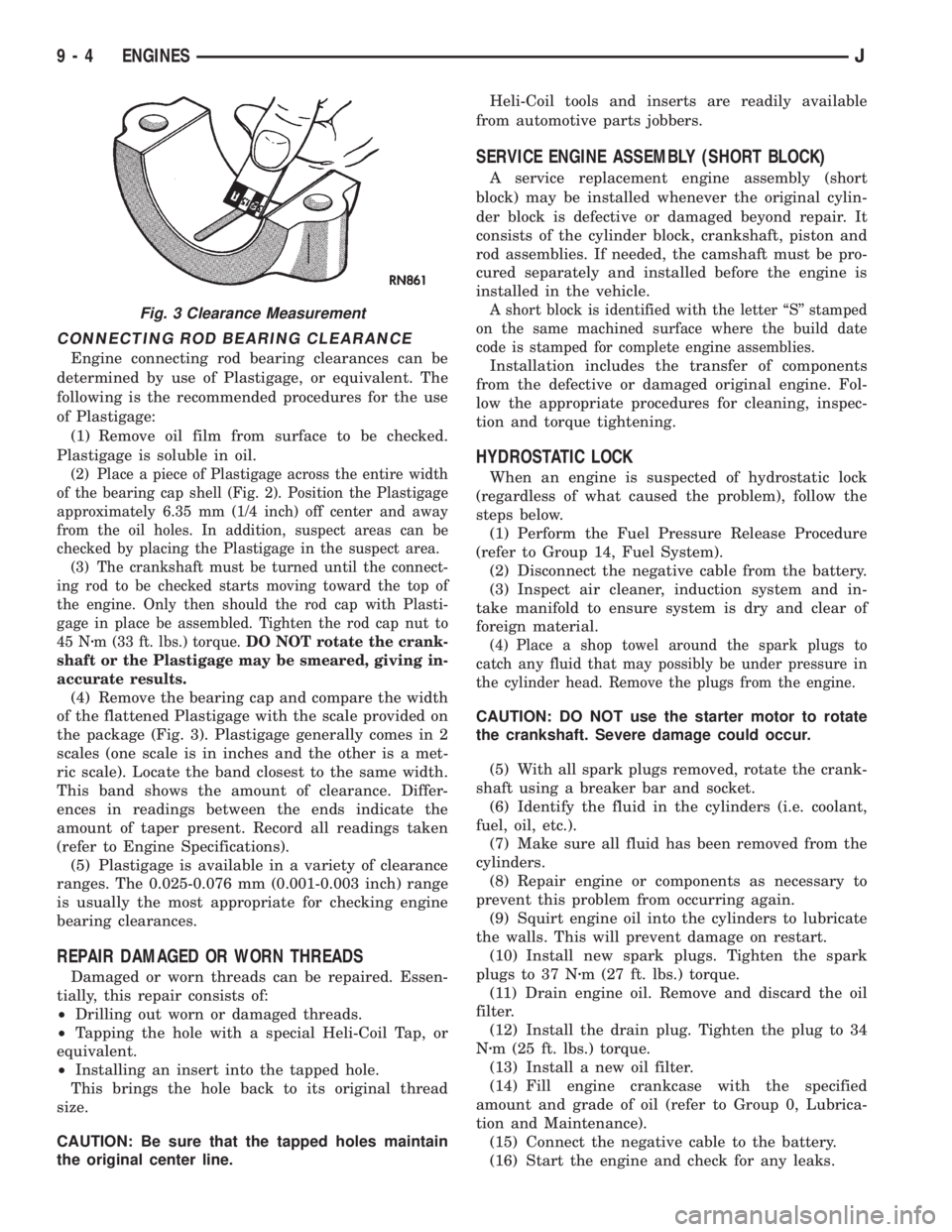
(2) Place a piece of Plastigage across the entire width
of the bearing cap shell (Fig. 2). Position the Plastigage
approximately 6.35 mm (1/4 inch) off center and away
from the oil holes. In addition, suspect areas can be
checked by placing the Plastigage in the suspect area.
(3) The crankshaft must be turned until the connect-
ing rod to be checked starts moving toward the top of
the engine. Only then should the rod cap with Plasti-
gage in place be assembled. Tighten the rod cap nut to
45 Nzm (33 ft. lbs.) torque.DO NOT rotate the crank-
shaft or the Plastigage may be smeared, giving in-
accurate results.
(4) Remove the bearing cap and compare the width
of the flattened Plastigage with the scale provided on
the package (Fig. 3). Plastigage generally comes in 2
scales (one scale is in inches and the other is a met-
ric scale). Locate the band closest to the same width.
This band shows the amount of clearance. Differ-
ences in readings between the ends indicate the
amount of taper present. Record all readings taken
(refer to Engine Specifications).
(5) Plastigage is available in a variety of clearance
ranges. The 0.025-0.076 mm (0.001-0.003 inch) range
is usually the most appropriate for checking engine
bearing clearances.
REPAIR DAMAGED OR WORN THREADS
Damaged or worn threads can be repaired. Essen-
tially, this repair consists of:
²Drilling out worn or damaged threads.
²Tapping the hole with a special Heli-Coil Tap, or
equivalent.
²Installing an insert into the tapped hole.
This brings the hole back to its original thread
size.
CAUTION: Be sure that the tapped holes maintain
the original center line.Heli-Coil tools and inserts are readily available
from automotive parts jobbers.
SERVICE ENGINE ASSEMBLY (SHORT BLOCK)
A service replacement engine assembly (short
block) may be installed whenever the original cylin-
der block is defective or damaged beyond repair. It
consists of the cylinder block, crankshaft, piston and
rod assemblies. If needed, the camshaft must be pro-
cured separately and installed before the engine is
installed in the vehicle.
A short block is identified with the letter ``S'' stamped
on the same machined surface where the build date
code is stamped for complete engine assemblies.
Installation includes the transfer of components
from the defective or damaged original engine. Fol-
low the appropriate procedures for cleaning, inspec-
tion and torque tightening.
HYDROSTATIC LOCK
When an engine is suspected of hydrostatic lock
(regardless of what caused the problem), follow the
steps below.
(1) Perform the Fuel Pressure Release Procedure
(refer to Group 14, Fuel System).
(2) Disconnect the negative cable from the battery.
(3) Inspect air cleaner, induction system and in-
take manifold to ensure system is dry and clear of
foreign material.
(4) Place a shop towel around the spark plugs to
catch any fluid that may possibly be under pressure in
the cylinder head. Remove the plugs from the engine.
CAUTION: DO NOT use the starter motor to rotate
the crankshaft. Severe damage could occur.
(5) With all spark plugs removed, rotate the crank-
shaft using a breaker bar and socket.
(6) Identify the fluid in the cylinders (i.e. coolant,
fuel, oil, etc.).
(7) Make sure all fluid has been removed from the
cylinders.
(8) Repair engine or components as necessary to
prevent this problem from occurring again.
(9) Squirt engine oil into the cylinders to lubricate
the walls. This will prevent damage on restart.
(10) Install new spark plugs. Tighten the spark
plugs to 37 Nzm (27 ft. lbs.) torque.
(11) Drain engine oil. Remove and discard the oil
filter.
(12) Install the drain plug. Tighten the plug to 34
Nzm (25 ft. lbs.) torque.
(13) Install a new oil filter.
(14) Fill engine crankcase with the specified
amount and grade of oil (refer to Group 0, Lubrica-
tion and Maintenance).
(15) Connect the negative cable to the battery.
(16) Start the engine and check for any leaks.
Fig. 3 Clearance Measurement
9 - 4 ENGINESJ
Page 1284 of 2158
ENGINE DIAGNOSIS
Engine diagnosis is helpful in determining the
causes of malfunctions not detected and remedied by
routine tune-ups.
These malfunctions may be classified as either per-
formance (e.g., engine idles rough and stalls) or me-
chanical (e.g., a strange noise).
Refer to the Service DiagnosisÐPerformance chart
and the Service DiagnosisÐMechanical chart for pos-
sible causes and corrections of malfunctions. Refer to
Group 14, Fuel System for the fuel system diagnosis.
GENERAL INFORMATION
Additional tests and diagnostic procedures may be
necessary for specific engine malfunctions that can
not be isolated with the Service Diagnosis charts. In-
formation concerning additional tests and diagnosis
is provided within the following diagnosis:
²Cylinder Compression Pressure Test.
²Cylinder Combustion Pressure Leakage Test.
²Engine Cylinder Head Gasket Failure Diagnosis.
²Intake Manifold Leakage Diagnosis.
INTAKE MANIFOLD LEAKAGE DIAGNOSIS
An intake manifold air leak is characterized by
lower than normal manifold vacuum. Also, one or
more cylinders may not be functioning.
WARNING: USE EXTREME CAUTION WHEN THE
ENGINE IS OPERATING. DO NOT STAND IN A DI-
RECT LINE WITH THE FAN. DO NOT PUT YOUR
HANDS NEAR THE PULLEYS, BELTS OR THE FAN.
DO NOT WEAR LOOSE CLOTHING.
METHOD 1
(1) Start the engine.
(2) Spray a small stream of water at the suspected
leak area.
(3) If a change in RPM'S, the area of the suspected
leak has been found.
(4) Repair as required.
CYLINDER COMPRESSION PRESSURE TEST
The results of a cylinder compression pressure test
can be utilized to diagnose several engine malfunc-
tions.
Ensure the battery is completely charged and the
engine starter motor is in good operating condition.
Otherwise the indicated compression pressures may
not be valid for diagnosis purposes.
(1) Clean the spark plug recesses with compressed
air.
(2) Remove the spark plugs.
(3) Secure the throttle in the wide-open position.
(4) Disconnect the ignition coil.(5) Insert a compression pressure gauge and rotate
the engine with the engine starter motor for three
revolutions.
(6) Record the compression pressure on the 3rd
revolution. Continue the test for the remaining cylin-
ders.
Refer to Engine Specifications for the correct en-
gine compression pressures.
ENGINE CYLINDER HEAD GASKET FAILURE
DIAGNOSIS
A leaking engine cylinder head gasket usually re-
sults in loss of power, loss of coolant and engine mis-
firing.
An engine cylinder head gasket leak can be located
between adjacent cylinders or between a cylinder and
the adjacent water jacket.
²An engine cylinder head gasket leaking between
adjacent cylinders is indicated by a loss of power
and/or engine misfire.
²An engine cylinder head gasket leaking between a
cylinder and an adjacent water jacket is indicated by
coolant foaming or overheating and loss of coolant.
CYLINDER-TO-CYLINDER LEAKAGE TEST
To determine if an engine cylinder head gasket is
leaking between adjacent cylinders; follow the proce-
dures outlined in Cylinder Compression Pressure
Test. An engine cylinder head gasket leaking between
adjacent cylinders will result in approximately a 50-
70% reduction in compression pressure.
CYLINDER-TO-WATER JACKET LEAKAGE
TEST
WARNING: USE EXTREME CAUTION WHEN THE
ENGINE IS OPERATING. DO NOT STAND IN A DI-
RECT LINE WITH THE FAN. DO NOT PUT YOUR
HANDS NEAR THE PULLEYS, BELTS OR THE FAN.
DO NOT WEAR LOOSE CLOTHING.
Remove the radiator cap.
Start the engine and allow it to warm up until the
engine thermostat opens.
If a large combustion/compression pressure leak ex-
ists, bubbles will be visible in the coolant.
If bubbles are not visible, install a radiator pres-
sure tester and pressurize the coolant system.
If a cylinder is leaking combustion pressure into
the water jacket, the tester pointer will pulsate with
every combustion stroke of the cylinder.
JENGINES 9 - 5
Page 1285 of 2158
CYLINDER COMBUSTION PRESSURE LEAKAGE
TEST
The combustion pressure leakage test provides an
accurate means for determining engine condition.
Combustion pressure leakage testing will detect:
²Exhaust and intake valve leaks (improper seat-
ing).
²Leaks between adjacent cylinders or into water
jacket.
²Any causes for combustion/compression pressure
loss.
WARNING: DO NOT REMOVE THE RADIATOR CAP
WITH THE SYSTEM HOT AND UNDER PRESSURE
BECAUSE SERIOUS BURNS FROM COOLANT CAN
OCCUR.
Check the coolant level and fill as required. DO
NOT install the radiator cap.
Start and operate the engine until it attains nor-
mal operating temperature, then turn the engine
OFF.
Remove the spark plugs.
Remove the oil filler cap.
Remove the air cleaner.
Calibrate the tester according to the manufactur-
er's instructions. The shop air source for testing
should maintain 483 kPa (70 psi) minimum, 1 379
kPa (200 psi) maximum and 552 kPa (80 psi) recom-
mended.
Perform the test procedures on each cylinder ac-
cording to the tester manufacturer's instructions.
While testing, listen for pressurized air escaping
through the throttle body, tailpipe and oil filler cap
opening. Check for bubbles in the radiator coolant.
All gauge pressure indications should be equal,
with no more than 25% leakage.
FOR EXAMPLE:At 552 kPa (80 psi) input pres-
sure, a minimum of 414 kPa (60 psi) should be main-
tained in the cylinder.
Refer to the Cylinder Combustion Pressure Leak-
age Test Diagnosis chart.
INSPECTION (ENGINE OIL LEAKS IN GENERAL)
Begin with a through visual inspection of the en-
gine, particularly at the area of the suspected leak. If
an oil leak source is not readily identifiable, the fol-
lowing steps should be followed:
(1) Do not clean or degrease the engine at this
time because some solvents may cause rubber to
swell, temporarily stopping the leak.
(2) Add an oil soluble dye (use as recommended by
manufacturer). Start the engine and let idle for ap-
proximately 15 minutes. Check the oil dipstick to
make sure the dye is thoroughly mixed as indicated
with a bright yellow color under a black light.(3) Using a black light, inspect the entire engine
for fluorescent dye, particularly at the suspected area
of oil leak. If the oil leak is found and identified, re-
pair per service manual instructions.
(4) If dye is not observed, drive the vehicle at var-
ious speeds for approximately 24km (15 miles), and
repeat step (3).
If the oil leak source is not positively identi-
fied at this time, proceed with the air leak detec-
tion test method as follows:
(1) Disconnect the breather cap to air cleaner hose
at the breather cap end. Cap or plug breather cap
nipple.
(2) Remove the PCV valve from the cylinder head
cover. Cap or plug the PCV valve grommet.
(3) Attach an air hose with pressure gauge and
regulator to the dipstick tube.
CAUTION: Do not subject the engine assembly to
more than 20.6 kpa (3 PSI) of test pressure.
(4) Gradually apply air pressure from 1 psi to 2.5
psi maximum while applying soapy water at the sus-
pected source. Adjust the regulator to the suitable
test pressure that provide the best bubbles which
will pinpoint the leak source. If the oil leak is de-
tected and identified, repair per service manual pro-
cedures.
(5) If the leakage occurs at the rear oil seal area,
refer to the section, Inspection for Rear Seal Area
Leak.
(6) If no leaks are detected, turn off the air supply
and remove the air hose and all plugs and caps. In-
stall the PCV valve and breather cap hose. Proceed
to step 7.
(7) Clean the oil off the suspect oil leak area using
a suitable solvent. Drive the vehicle at various
speeds approximately 24 km (15 miles). Inspect the
engine for signs of an oil leak by using a black light.
INSPECTION FOR REAR SEAL AREA LEAKS
Since it is sometimes difficult to determine the
source of an oil leak in the rear seal area of the en-
gine, a more involved inspection is necessary. The fol-
lowing steps should be followed to help pinpoint the
source of the leak.
If the leakage occurs at the crankshaft rear oil seal
area:
(1) Disconnect the battery.
(2) Raise the vehicle.
(3) Remove torque converter or clutch housing
cover and inspect rear of block for evidence of oil.
Use a black light to check for the oil leak:
(a) Circular spray pattern generally indicates
seal leakage or crankshaft damage.
(b) Where leakage tends to run straight down,
possible causes are a porous block, distributor seal,
camshaft bore cup plugs oil galley pipe plugs, oil
9 - 6 ENGINESJ
Page 1297 of 2158
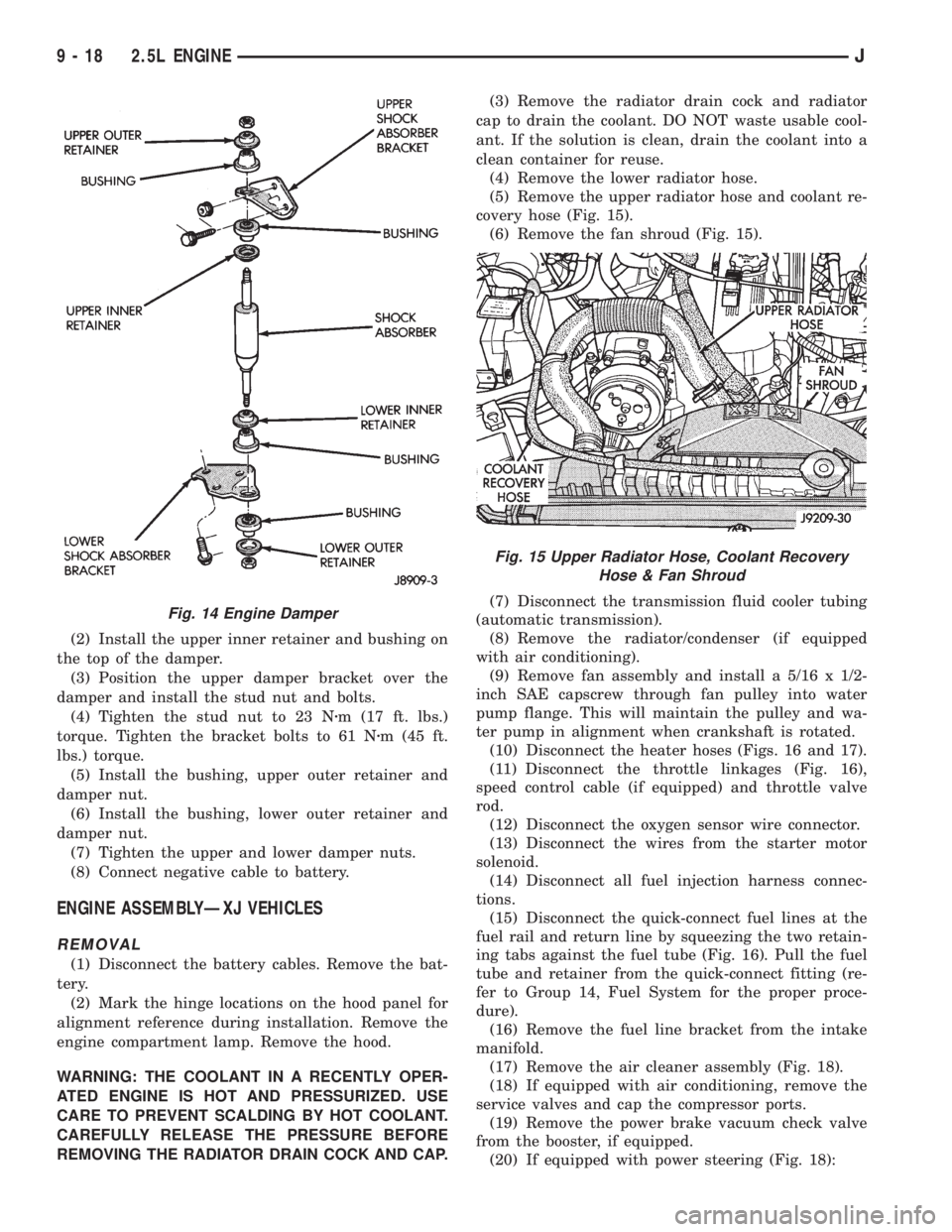
(2) Install the upper inner retainer and bushing on
the top of the damper.
(3) Position the upper damper bracket over the
damper and install the stud nut and bolts.
(4) Tighten the stud nut to 23 Nzm (17 ft. lbs.)
torque. Tighten the bracket bolts to 61 Nzm (45 ft.
lbs.) torque.
(5) Install the bushing, upper outer retainer and
damper nut.
(6) Install the bushing, lower outer retainer and
damper nut.
(7) Tighten the upper and lower damper nuts.
(8) Connect negative cable to battery.
ENGINE ASSEMBLYÐXJ VEHICLES
REMOVAL
(1) Disconnect the battery cables. Remove the bat-
tery.
(2) Mark the hinge locations on the hood panel for
alignment reference during installation. Remove the
engine compartment lamp. Remove the hood.
WARNING: THE COOLANT IN A RECENTLY OPER-
ATED ENGINE IS HOT AND PRESSURIZED. USE
CARE TO PREVENT SCALDING BY HOT COOLANT.
CAREFULLY RELEASE THE PRESSURE BEFORE
REMOVING THE RADIATOR DRAIN COCK AND CAP.(3) Remove the radiator drain cock and radiator
cap to drain the coolant. DO NOT waste usable cool-
ant. If the solution is clean, drain the coolant into a
clean container for reuse.
(4) Remove the lower radiator hose.
(5) Remove the upper radiator hose and coolant re-
covery hose (Fig. 15).
(6) Remove the fan shroud (Fig. 15).
(7) Disconnect the transmission fluid cooler tubing
(automatic transmission).
(8) Remove the radiator/condenser (if equipped
with air conditioning).
(9) Remove fan assembly and install a 5/16 x 1/2-
inch SAE capscrew through fan pulley into water
pump flange. This will maintain the pulley and wa-
ter pump in alignment when crankshaft is rotated.
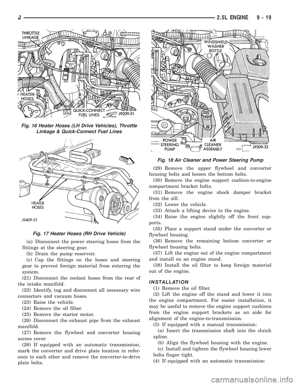
(10) Disconnect the heater hoses (Figs. 16 and 17).
(11) Disconnect the throttle linkages (Fig. 16),
speed control cable (if equipped) and throttle valve
rod.
(12) Disconnect the oxygen sensor wire connector.
(13) Disconnect the wires from the starter motor
solenoid.
(14) Disconnect all fuel injection harness connec-
tions.
(15) Disconnect the quick-connect fuel lines at the
fuel rail and return line by squeezing the two retain-
ing tabs against the fuel tube (Fig. 16). Pull the fuel
tube and retainer from the quick-connect fitting (re-
fer to Group 14, Fuel System for the proper proce-
dure).
(16) Remove the fuel line bracket from the intake
manifold.
(17) Remove the air cleaner assembly (Fig. 18).
(18) If equipped with air conditioning, remove the
service valves and cap the compressor ports.
(19) Remove the power brake vacuum check valve
from the booster, if equipped.
(20) If equipped with power steering (Fig. 18):
Fig. 14 Engine Damper
Fig. 15 Upper Radiator Hose, Coolant Recovery
Hose & Fan Shroud
9 - 18 2.5L ENGINEJ
Page 1298 of 2158
(a) Disconnect the power steering hoses from the
fittings at the steering gear.
(b) Drain the pump reservoir.
(c) Cap the fittings on the hoses and steering
gear to prevent foreign material from entering the
system.
(21) Disconnect the coolant hoses from the rear of
the intake manifold.
(22) Identify, tag and disconnect all necessary wire
connectors and vacuum hoses.
(23) Raise the vehicle.
(24) Remove the oil filter.
(25) Remove the starter motor.
(26) Disconnect the exhaust pipe from the exhaust
manifold.
(27) Remove the flywheel and converter housing
access cover.
(28) If equipped with an automatic transmission,
mark the converter and drive plate location in refer-
ence to each other and remove the converter-to-drive
plate bolts.(29) Remove the upper flywheel and converter
housing bolts and loosen the bottom bolts.
(30) Remove the engine support cushion-to-engine
compartment bracket bolts.
(31) Remove the engine shock damper bracket
from the sill.
(32) Lower the vehicle.
(33) Attach a lifting device to the engine.
(34) Raise the engine slightly off the front sup-
ports.
(35) Place a support stand under the converter or
flywheel housing.
(36) Remove the remaining bottom converter or
flywheel housing bolts.
(37) Lift the engine out of the engine compartment
and install on an engine stand.
(38) Install the oil filter to keep foreign material
out of the engine.
INSTALLATION
(1) Remove the oil filter.
(2) Lift the engine off the stand and lower it into
the engine compartment. For easier installation, it
may be useful to remove the engine support cushions
from the engine support brackets as an aide for
alignment of the engine-to-transmission.
(3) If equipped with a manual transmission:
(a) Insert the transmission shaft into the clutch
spline.
(b) Align the flywheel housing with the engine.
(c) Install and tighten the flywheel housing lower
bolts finger tight.
(4) If equipped with an automatic transmission:
Fig. 16 Heater Hoses (LH Drive Vehicles), Throttle
Linkage & Quick-Connect Fuel Lines
Fig. 17 Heater Hoses (RH Drive Vehicle)
Fig. 18 Air Cleaner and Power Steering Pump
J2.5L ENGINE 9 - 19