1995 JEEP YJ ESP
[x] Cancel search: ESPPage 1441 of 2158
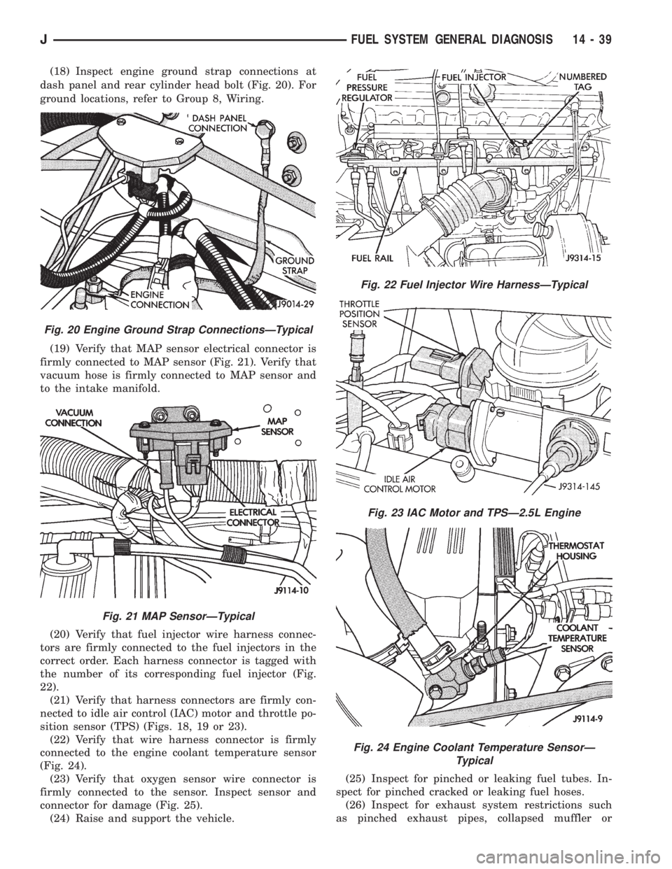
(18) Inspect engine ground strap connections at
dash panel and rear cylinder head bolt (Fig. 20). For
ground locations, refer to Group 8, Wiring.
(19) Verify that MAP sensor electrical connector is
firmly connected to MAP sensor (Fig. 21). Verify that
vacuum hose is firmly connected to MAP sensor and
to the intake manifold.
(20) Verify that fuel injector wire harness connec-
tors are firmly connected to the fuel injectors in the
correct order. Each harness connector is tagged with
the number of its corresponding fuel injector (Fig.
22).
(21) Verify that harness connectors are firmly con-
nected to idle air control (IAC) motor and throttle po-
sition sensor (TPS) (Figs. 18, 19 or 23).
(22) Verify that wire harness connector is firmly
connected to the engine coolant temperature sensor
(Fig. 24).
(23) Verify that oxygen sensor wire connector is
firmly connected to the sensor. Inspect sensor and
connector for damage (Fig. 25).
(24) Raise and support the vehicle.(25) Inspect for pinched or leaking fuel tubes. In-
spect for pinched cracked or leaking fuel hoses.
(26) Inspect for exhaust system restrictions such
as pinched exhaust pipes, collapsed muffler or
Fig. 20 Engine Ground Strap ConnectionsÐTypical
Fig. 21 MAP SensorÐTypical
Fig. 22 Fuel Injector Wire HarnessÐTypical
Fig. 23 IAC Motor and TPSÐ2.5L Engine
Fig. 24 Engine Coolant Temperature SensorÐ
Typical
JFUEL SYSTEM GENERAL DIAGNOSIS 14 - 39
Page 1458 of 2158
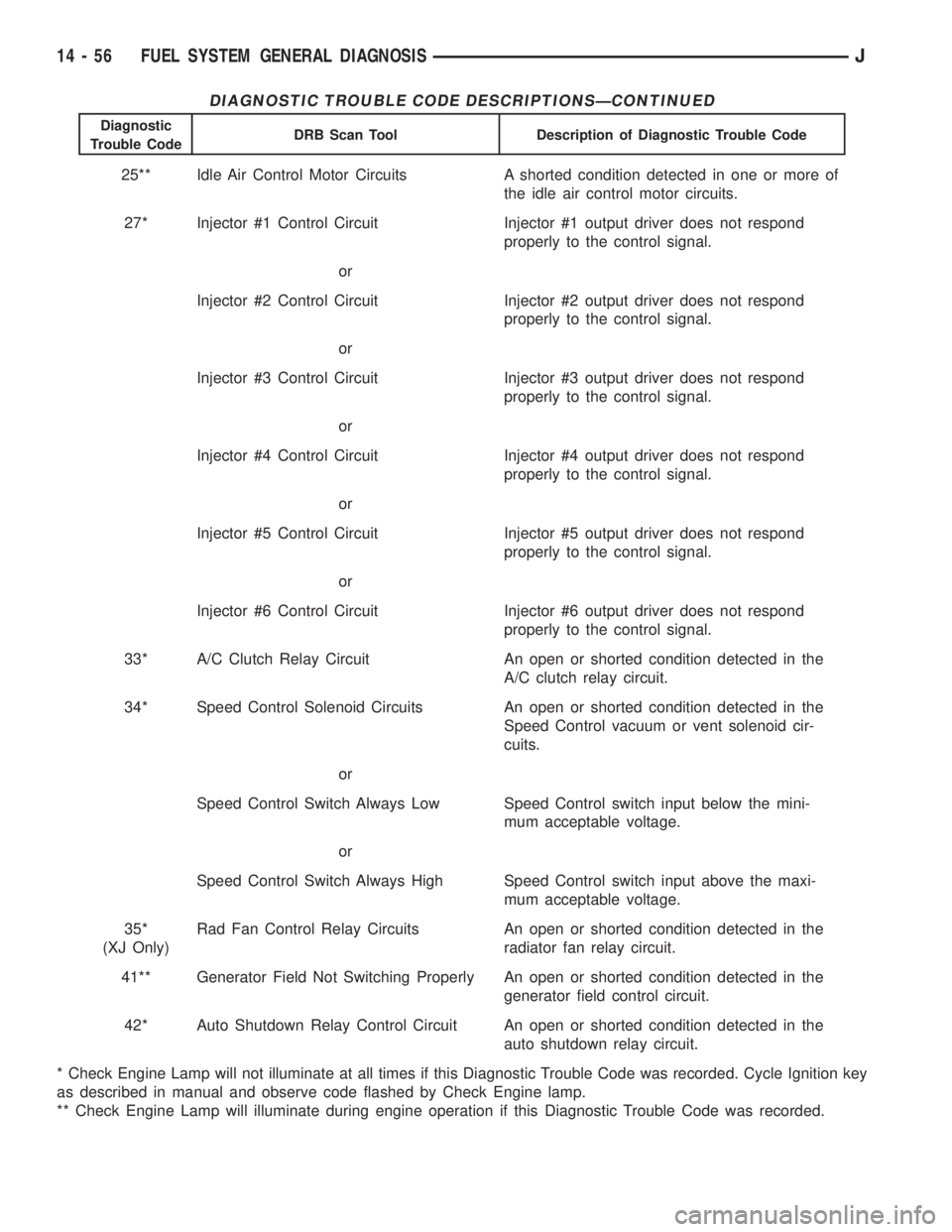
DIAGNOSTIC TROUBLE CODE DESCRIPTIONSÐCONTINUED
Diagnostic
Trouble CodeDRB Scan Tool Description of Diagnostic Trouble Code
25** Idle Air Control Motor Circuits A shorted condition detected in one or more of
the idle air control motor circuits.
27* Injector #1 Control Circuit Injector #1 output driver does not respond
properly to the control signal.
or
Injector #2 Control Circuit Injector #2 output driver does not respond
properly to the control signal.
or
Injector #3 Control Circuit Injector #3 output driver does not respond
properly to the control signal.
or
Injector #4 Control Circuit Injector #4 output driver does not respond
properly to the control signal.
or
Injector #5 Control Circuit Injector #5 output driver does not respond
properly to the control signal.
or
Injector #6 Control Circuit Injector #6 output driver does not respond
properly to the control signal.
33* A/C Clutch Relay Circuit An open or shorted condition detected in the
A/C clutch relay circuit.
34* Speed Control Solenoid Circuits An open or shorted condition detected in the
Speed Control vacuum or vent solenoid cir-
cuits.
or
Speed Control Switch Always Low Speed Control switch input below the mini-
mum acceptable voltage.
or
Speed Control Switch Always High Speed Control switch input above the maxi-
mum acceptable voltage.
35*
(XJ Only)Rad Fan Control Relay Circuits An open or shorted condition detected in the
radiator fan relay circuit.
41** Generator Field Not Switching Properly An open or shorted condition detected in the
generator field control circuit.
42* Auto Shutdown Relay Control Circuit An open or shorted condition detected in the
auto shutdown relay circuit.
* Check Engine Lamp will not illuminate at all times if this Diagnostic Trouble Code was recorded. Cycle Ignition key
as described in manual and observe code flashed by Check Engine lamp.
** Check Engine Lamp will illuminate during engine operation if this Diagnostic Trouble Code was recorded.
14 - 56 FUEL SYSTEM GENERAL DIAGNOSISJ
Page 1614 of 2158
GEAR AND SYNCHRO INSPECTION
Install the synchro rings on their respective gears.
Rotate each ring on the gear and note synchro action.
Replace any synchro ring that exhibits a lack of
braking action or binds on the gear. Also replace any
ring that is worn or has chipped or broken teeth.
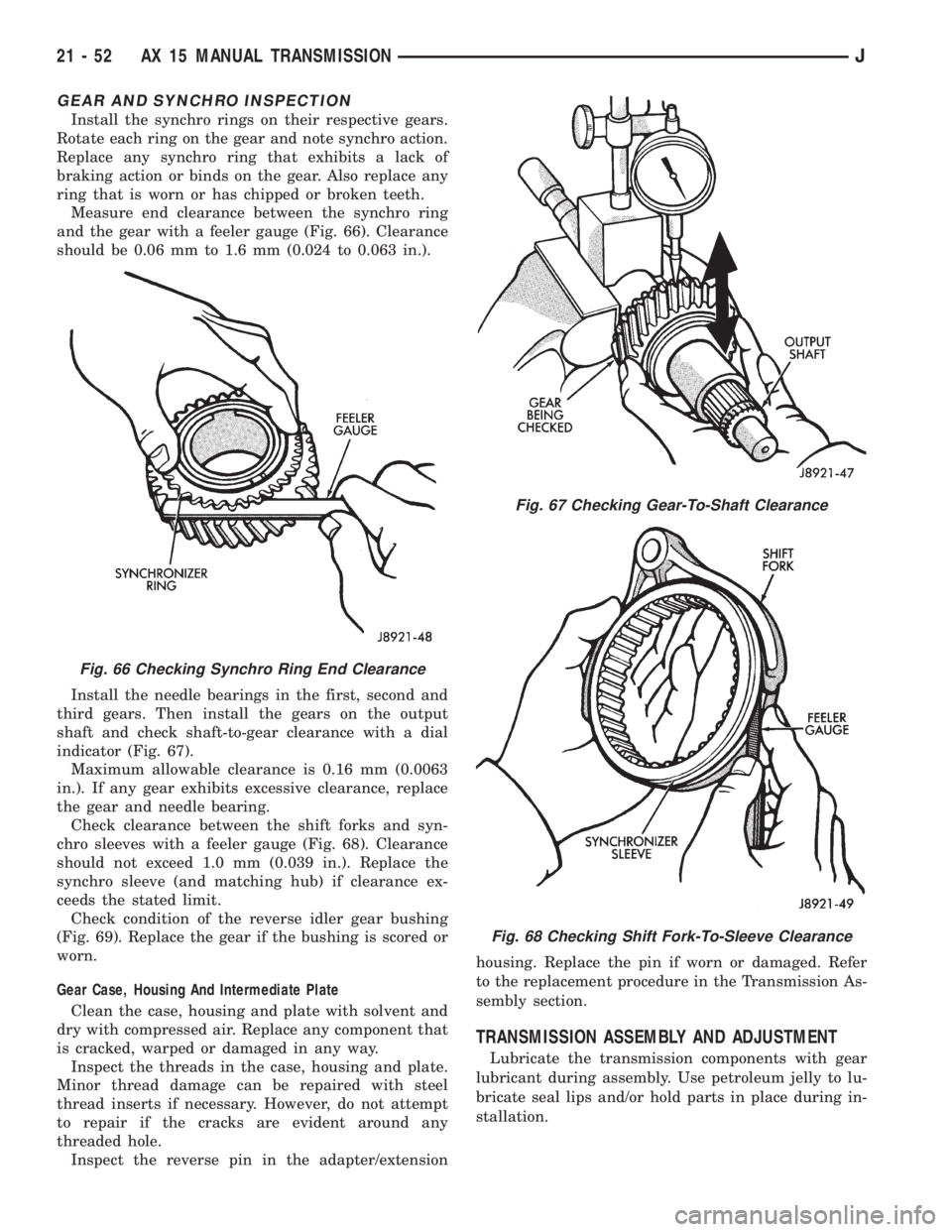
Measure end clearance between the synchro ring
and the gear with a feeler gauge (Fig. 66). Clearance
should be 0.06 mm to 1.6 mm (0.024 to 0.063 in.).
Install the needle bearings in the first, second and
third gears. Then install the gears on the output
shaft and check shaft-to-gear clearance with a dial
indicator (Fig. 67).
Maximum allowable clearance is 0.16 mm (0.0063
in.). If any gear exhibits excessive clearance, replace
the gear and needle bearing.
Check clearance between the shift forks and syn-
chro sleeves with a feeler gauge (Fig. 68). Clearance
should not exceed 1.0 mm (0.039 in.). Replace the
synchro sleeve (and matching hub) if clearance ex-
ceeds the stated limit.
Check condition of the reverse idler gear bushing
(Fig. 69). Replace the gear if the bushing is scored or
worn.
Gear Case, Housing And Intermediate Plate
Clean the case, housing and plate with solvent and
dry with compressed air. Replace any component that
is cracked, warped or damaged in any way.
Inspect the threads in the case, housing and plate.
Minor thread damage can be repaired with steel
thread inserts if necessary. However, do not attempt
to repair if the cracks are evident around any
threaded hole.
Inspect the reverse pin in the adapter/extensionhousing. Replace the pin if worn or damaged. Refer
to the replacement procedure in the Transmission As-
sembly section.
TRANSMISSION ASSEMBLY AND ADJUSTMENT
Lubricate the transmission components with gear
lubricant during assembly. Use petroleum jelly to lu-
bricate seal lips and/or hold parts in place during in-
stallation.
Fig. 66 Checking Synchro Ring End Clearance
Fig. 67 Checking Gear-To-Shaft Clearance
Fig. 68 Checking Shift Fork-To-Sleeve Clearance
21 - 52 AX 15 MANUAL TRANSMISSIONJ
Page 1635 of 2158
Test Two-Transmission In 2 Range
This test checks pump output and pressure
regulation. Use 100 psi Test Gauge C-3292 for
this test.
(1) Connect test gauge to line pressure port (Fig.
4).
(2) Start and run engine at 1000 rpm.
(3) Move valve body selector lever one detent rear-
ward from full forward position (this is 2 range).
(4) Move transmission throttle lever from full for-
ward to full rearward position and read pressure at
both gauges.
(5) Line pressure should be 54-60 psi (372-414
kPa) with throttle lever forward and gradually in-
crease to 90-96 psi (620-662 kPa) as lever is moved
rearward.
Test Three-Transmission In Third Gear
This test checks pressure regulation and con-
dition of the front and rear clutch circuits.
Both gauges are required for this test.
(1) Connect one test gauge to line pressure port
and other gauge to front servo pressure port (Fig. 4).
Either gauge can be used at either port.
(2) Start and run engine at 1600 rpm.
(3) Move selector lever two detents rearward from
full forward position. This is D range.
(4) Read pressures on both gauges as transmission
throttle lever is moved from full forward to full rear-
ward position.
(a) Line pressure in third gear, should be 54-60
psi (372-414 kPa) with throttle lever forward and
gradually increase as lever is moved rearward.
(b) Front servo pressure in third gear, should be
within 3 psi (21 kPa) of line pressure, up to down-
shift point.
Test Four-Transmission In Reverse
This test checks pump output, pressure regu-
lation and the front clutch and rear servo cir-
cuits. Use 300 psi Pressure Test Gauge C-3293
for this test.
(1) Connect pressure test gauge to rear servo port
(Fig. 5).
(2) Start and run engine at 1600 rpm for test.
(3) Move valve body selector lever four detents
rearward from full forward position. This is Reverse
range.
(4) Move throttle lever all way forward then all the
way rearward and note gauge readings.
(5) Pressure should be 145 - 175 psi (1000-1207
kPa) with lever forward and increase to 230 - 280 psi
(1586-1931 kPa) as lever is moved rearward.
Test Five-Governor Pressure
This test checks governor operation by mea-
suring governor pressure response to changesin engine speed. It is usually not necessary to
check governor operation unless shift speeds
are incorrect or if the transmission will not
shift up or down. Use 100 psi Pressure Test
Gauge C-3292 for this test.
(1) Connect test gauge to governor pressure port
(Figs. 5 and 6).
(2) Move selector lever to D range.
(3) Apply service brakes. Start and run engine at
curb idle speed and note pressure. At idle and with
wheels stopped, pressure should be zero to 1-1/2 psi
maximum. If pressure exceeds this figure, governor
valve or weights are sticking open.
(4) Slowly increase engine speed and observe
speedometer and pressure test gauge. Governor pres-
sure should increase in proportion to vehicle speed
(approximately 1 psi for every 1 mph shown on
speedometer).
(5) Governor pressure rise should be smooth and
drop back to 0 to 1-1/2 psi when throttle is closed
and wheels are stopped.
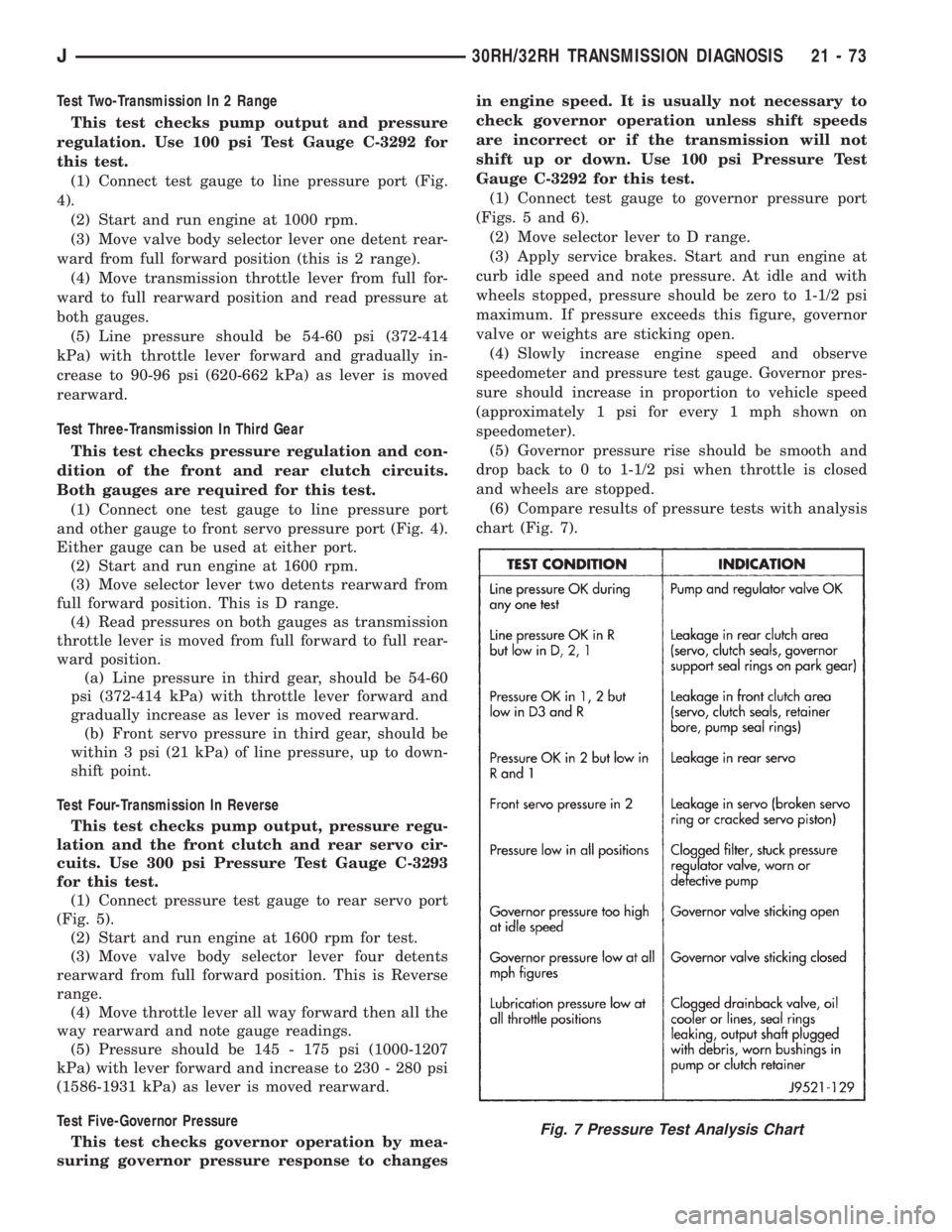
(6) Compare results of pressure tests with analysis
chart (Fig. 7).
Fig. 7 Pressure Test Analysis Chart
J30RH/32RH TRANSMISSION DIAGNOSIS 21 - 73
Page 1672 of 2158
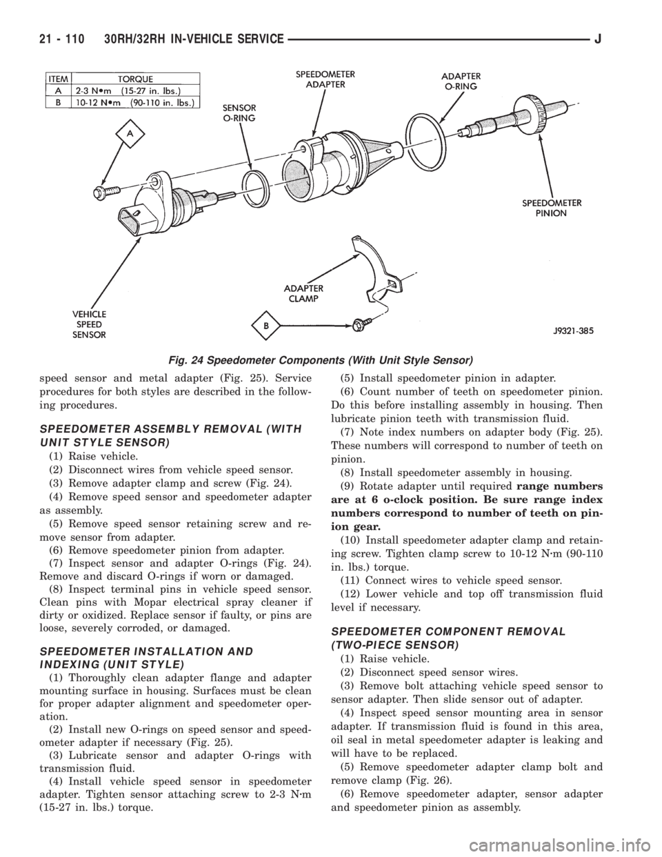
speed sensor and metal adapter (Fig. 25). Service
procedures for both styles are described in the follow-
ing procedures.
SPEEDOMETER ASSEMBLY REMOVAL (WITH
UNIT STYLE SENSOR)
(1) Raise vehicle.
(2) Disconnect wires from vehicle speed sensor.
(3) Remove adapter clamp and screw (Fig. 24).
(4) Remove speed sensor and speedometer adapter
as assembly.
(5) Remove speed sensor retaining screw and re-
move sensor from adapter.
(6) Remove speedometer pinion from adapter.
(7) Inspect sensor and adapter O-rings (Fig. 24).
Remove and discard O-rings if worn or damaged.
(8) Inspect terminal pins in vehicle speed sensor.
Clean pins with Mopar electrical spray cleaner if
dirty or oxidized. Replace sensor if faulty, or pins are
loose, severely corroded, or damaged.
SPEEDOMETER INSTALLATION AND
INDEXING (UNIT STYLE)
(1) Thoroughly clean adapter flange and adapter
mounting surface in housing. Surfaces must be clean
for proper adapter alignment and speedometer oper-
ation.
(2) Install new O-rings on speed sensor and speed-
ometer adapter if necessary (Fig. 25).
(3) Lubricate sensor and adapter O-rings with
transmission fluid.
(4) Install vehicle speed sensor in speedometer
adapter. Tighten sensor attaching screw to 2-3 Nzm
(15-27 in. lbs.) torque.(5) Install speedometer pinion in adapter.
(6) Count number of teeth on speedometer pinion.
Do this before installing assembly in housing. Then
lubricate pinion teeth with transmission fluid.
(7) Note index numbers on adapter body (Fig. 25).
These numbers will correspond to number of teeth on
pinion.
(8) Install speedometer assembly in housing.
(9) Rotate adapter until requiredrange numbers
are at 6 o-clock position. Be sure range index
numbers correspond to number of teeth on pin-
ion gear.
(10) Install speedometer adapter clamp and retain-
ing screw. Tighten clamp screw to 10-12 Nzm (90-110
in. lbs.) torque.
(11) Connect wires to vehicle speed sensor.
(12) Lower vehicle and top off transmission fluid
level if necessary.
SPEEDOMETER COMPONENT REMOVAL
(TWO-PIECE SENSOR)
(1) Raise vehicle.
(2) Disconnect speed sensor wires.
(3) Remove bolt attaching vehicle speed sensor to
sensor adapter. Then slide sensor out of adapter.
(4) Inspect speed sensor mounting area in sensor
adapter. If transmission fluid is found in this area,
oil seal in metal speedometer adapter is leaking and
will have to be replaced.
(5) Remove speedometer adapter clamp bolt and
remove clamp (Fig. 26).
(6) Remove speedometer adapter, sensor adapter
and speedometer pinion as assembly.
Fig. 24 Speedometer Components (With Unit Style Sensor)
21 - 110 30RH/32RH IN-VEHICLE SERVICEJ
Page 1673 of 2158
SPEEDOMETER COMPONENT INSTALLATION
AND INDEXING (TWO-PIECE SENSOR)
(1) Replace speedometer O-ring if cut, torn, or
worn.
(2) If oil seal in metal speedometer adapter needs
replacement, remove old seal with pointed tool. Then
install new seal with Special Tool C-4004. Push seal
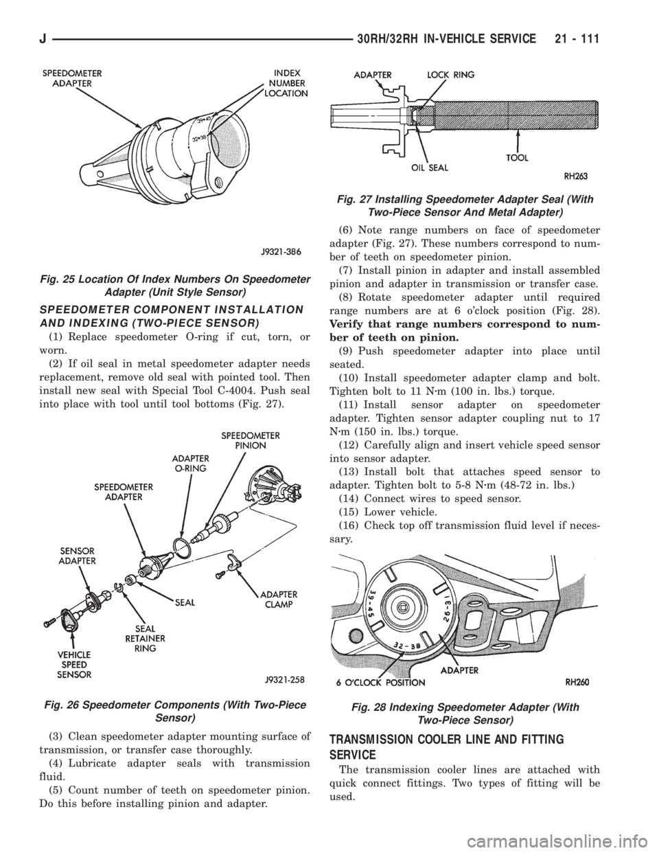
into place with tool until tool bottoms (Fig. 27).
(3) Clean speedometer adapter mounting surface of
transmission, or transfer case thoroughly.
(4) Lubricate adapter seals with transmission
fluid.
(5) Count number of teeth on speedometer pinion.
Do this before installing pinion and adapter.(6) Note range numbers on face of speedometer
adapter (Fig. 27). These numbers correspond to num-
ber of teeth on speedometer pinion.
(7) Install pinion in adapter and install assembled
pinion and adapter in transmission or transfer case.
(8) Rotate speedometer adapter until required
range numbers are at 6 o'clock position (Fig. 28).
Verify that range numbers correspond to num-
ber of teeth on pinion.
(9) Push speedometer adapter into place until
seated.
(10) Install speedometer adapter clamp and bolt.
Tighten bolt to 11 Nzm (100 in. lbs.) torque.
(11) Install sensor adapter on speedometer
adapter. Tighten sensor adapter coupling nut to 17
Nzm (150 in. lbs.) torque.
(12) Carefully align and insert vehicle speed sensor
into sensor adapter.
(13) Install bolt that attaches speed sensor to
adapter. Tighten bolt to 5-8 Nzm (48-72 in. lbs.)
(14) Connect wires to speed sensor.
(15) Lower vehicle.
(16) Check top off transmission fluid level if neces-
sary.
TRANSMISSION COOLER LINE AND FITTING
SERVICE
The transmission cooler lines are attached with
quick connect fittings. Two types of fitting will be
used.
Fig. 25 Location Of Index Numbers On Speedometer
Adapter (Unit Style Sensor)
Fig. 26 Speedometer Components (With Two-Piece
Sensor)
Fig. 27 Installing Speedometer Adapter Seal (With
Two-Piece Sensor And Metal Adapter)
Fig. 28 Indexing Speedometer Adapter (With
Two-Piece Sensor)
J30RH/32RH IN-VEHICLE SERVICE 21 - 111
Page 1704 of 2158
planetary. All the washers have four locating tabs on
them. These tabs fit in the holes or slots provided in
each planetary gear.
Inspect the output shaft carefully. Pay particular
attention to the machined bushing/bearing surfaces
on the shaft and the governor valve shaft bore at the
shaft rear.
Replace the output shaft if the machined surfaces
are scored, pitted, or damaged in any way. Also re-
place the shaft if the splines are damaged, or exhib-
it cracks at any location (especially at the governor
valve shaft bore).
The annulus gears can be removed from their sup-
ports if necessary. Just remove the snap rings and sep-
arate the two parts when replacement is necessary. In
addition, the annulus gear bushings can be replaced if
severely worn, or scored. However it is not necessary to
replace the bushings if they only exhibit normal wear.
Check bushing fit on the output shaft to be sure.
ASSEMBLING PLANETARY GEARTRAIN
(1) Lubricate output shaft and planetary components
with transmission fluid. Use petroleum jelly to lubricate
and hold thrust washers and plates in position.
(2) Assemble rear annulus gear and support if dis-
assembled. Be sure support snap ring is seated and
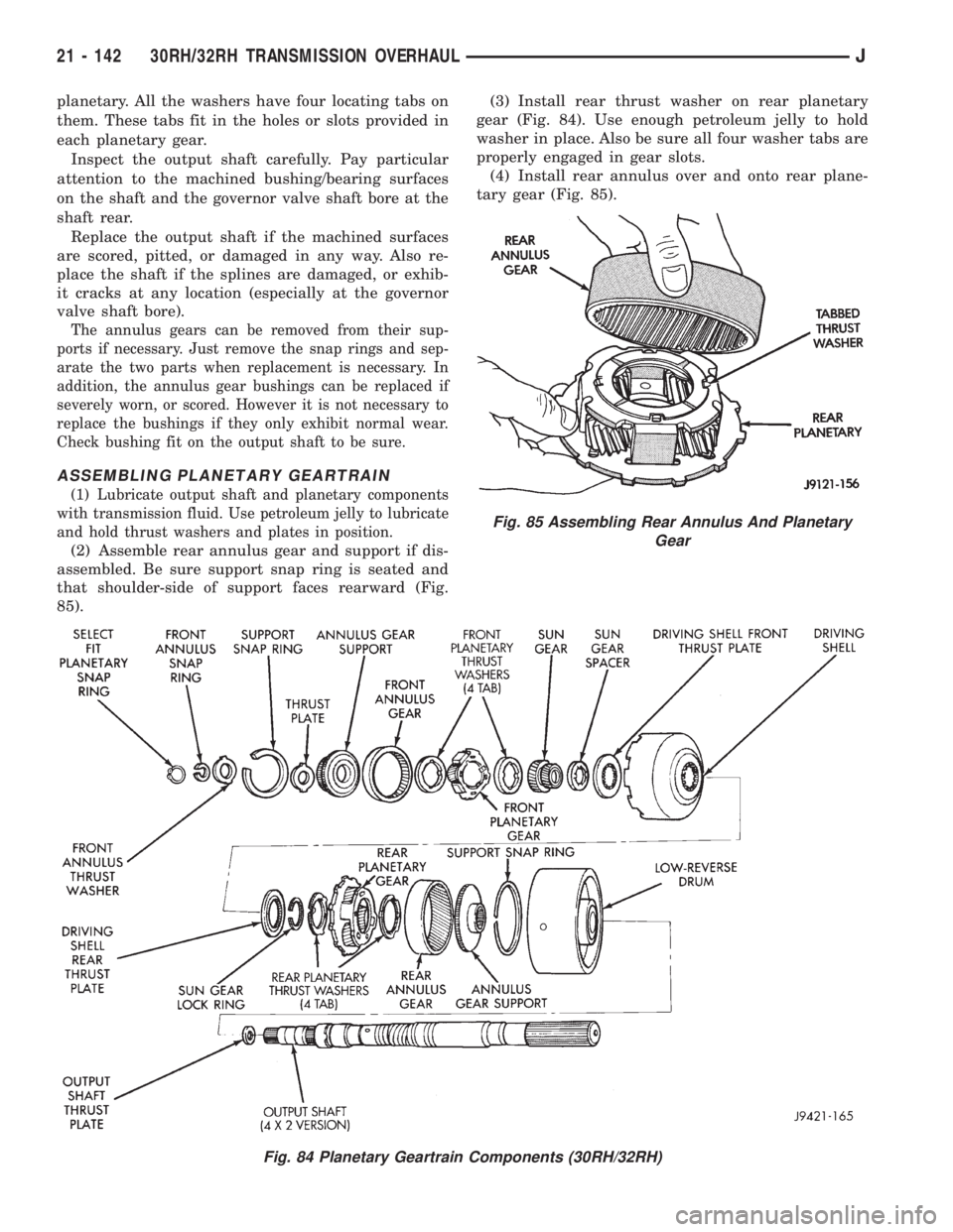
that shoulder-side of support faces rearward (Fig.
85).(3) Install rear thrust washer on rear planetary
gear (Fig. 84). Use enough petroleum jelly to hold
washer in place. Also be sure all four washer tabs are
properly engaged in gear slots.
(4) Install rear annulus over and onto rear plane-
tary gear (Fig. 85).
Fig. 84 Planetary Geartrain Components (30RH/32RH)
Fig. 85 Assembling Rear Annulus And Planetary
Gear
21 - 142 30RH/32RH TRANSMISSION OVERHAULJ
Page 1728 of 2158
ranges. Third gear ratio is 1:1. A separate planetary
gear set provides overdrive operation in fourth gear.
TRANSMISSION RANGES AND SHIFT LEVER
POSITIONS
The AW-4 transmission has six ranges and shift le-
ver positions. Park, Reverse and Neutral are conven-
tional and mechanically operated. The 1-2, 3 and D
ranges provide electronically controlled shifting.
The 1-2 position provides first and second gear
only. The 3 position provides first, second and third
gear.
The D range provides first through fourth gear.
Overdrive fourth gear range is available only when
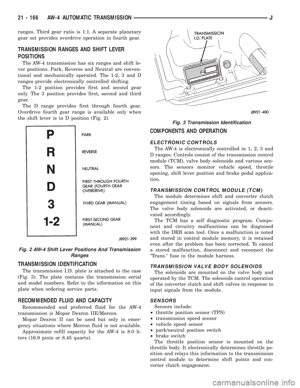
the shift lever is in D position (Fig. 2).
TRANSMISSION IDENTIFICATION
The transmission I.D. plate is attached to the case
(Fig. 3). The plate contains the transmission serial
and model numbers. Refer to the information on this
plate when ordering service parts.
RECOMMENDED FLUID AND CAPACITY
Recommended and preferred fluid for the AW-4
transmission is Mopar Dexron IIE/Mercon.
Mopar Dexron II can be used but only in emer-
gency situations where Mercon fluid is not available.
Approximate refill capacity for the AW-4 is 8.0 li-
ters (16.9 pints or 8.45 quarts).
COMPONENTS AND OPERATION
ELECTRONIC CONTROLS
The AW-4 is electronically controlled in 1, 2, 3 and
D ranges. Controls consist of the transmission control
module (TCM), valve body solenoids and various sen-
sors. The sensors monitor vehicle speed, throttle
opening, shift lever position and brake pedal applica-
tion.
TRANSMISSION CONTROL MODULE (TCM)
The module determines shift and converter clutch
engagement timing based on signals from sensors.
The valve body solenoids are activated, or deacti-
vated accordingly.
The TCM has a self diagnostic program. Compo-
nent and circuitry malfunctions can be diagnosed
with the DRB scan tool. Once a malfunction is noted
and stored in control module memory, it is retained
even after the problem has been corrected. To cancel
a stored malfunction, disconnect and reconnect the
9Trans.9fuse in the module harness.
TRANSMISSION VALVE BODY SOLENOIDS
The solenoids are mounted on the valve body and
operated by the TCM. The solenoids control operation
of the converter clutch and shift valves in response to
input signals from the module.
SENSORS
Sensors include:
²throttle position sensor (TPS)
²transmission speed sensor
²vehicle speed sensor
²park/neutral position switch
²brake switch
The throttle position sensor is mounted on the
throttle body. It electronically determines throttle po-
sition and relays this information to the transmission
control module to determine shift points and con-
verter clutch engagement.
Fig. 2 AW-4 Shift Lever Positions And Transmission
Ranges
Fig. 3 Transmission Identification
21 - 166 AW-4 AUTOMATIC TRANSMISSIONJ