1995 JEEP YJ ESP
[x] Cancel search: ESPPage 417 of 2158

VEHICLE SPEED CONTROL SYSTEM
CONTENTS
page page
DIAGNOSIS............................. 2
GENERAL INFORMATION.................. 1SERVICE PROCEDURES................... 9
GENERAL INFORMATION
The vehicle speed control system (Fig. 1) is an
available option on all XJ (Cherokee) models. The
system is electronically controlled and vacuum oper-
ated. Following are general descriptions of the major
components in the vehicle speed control system. Re-
fer to Group 8W - Wiring Diagrams for complete cir-
cuit descriptions and diagrams.
SPEED CONTROL SERVO
The speed control servo is mounted to a bracket on
the right side inner fender shield in the engine com-
partment. The servo unit consists of a solenoid valve
body, a vacuum servo and the mounting bracket. The
PCM controls the solenoid valve body. The solenoid
valve body controls the application and release of
vacuum to the diaphragm of the vacuum servo. The
servo unit cannot be repaired and is serviced only as
a complete assembly.
SPEED CONTROL SWITCH
The speed control switch module is mounted to the
center of the steering wheel below the driver's airbag
module. The PCM monitors the state of the speed
control switches. The individual switches are labeled:
OFF/ON, RESUME/ACCEL, SET/COAST. Refer to
the owner's manual for more information on speed
control switch functions and setting procedures. The
individual switches cannot be repaired. If one switch
fails, the entire switch module must be replaced.
STOP LAMP SWITCH
Vehicles with the speed control option use a dual
function stop lamp switch. The switch is mounted in
the same location as the conventional stop lamp
switch, on the brake pedal mounting bracket under
the instrument panel. The PCM monitors the state of
the dual function stop lamp switch. Refer to Group 5
- Brakes for more information on stop lamp switch
service and adjustment procedures.
SERVO CABLE
The speed control servo cable is connected betweenthe speed control vacuum servo diaphragm and the
throttle control linkage. This cable causes the throt-
tle control linkage to open or close the throttle valve
in response to movement of the vacuum servo dia-
phragm.
POWERTRAIN CONTROL MODULE
The speed control electronic control circuitry is in-
tegrated into the Powertrain Control Module (PCM).
The PCM is located in the engine compartment on
the left side inner fender shield. The PCM speed con-
trol functions are monitored by the On-Board Diag-
nostics (OBD). All OBD-sensed systems are
monitored by the PCM. Each monitored circuit is as-
signed a Diagnostic Trouble Code (DTC). The PCM
will store a DTC in electronic memory for any failure
it detects. See Using On-Board Diagnostic System in
this group for more information. The PCM cannot be
repaired and must be replaced if faulty.
VACUUM RESERVOIR
The vacuum reservoir is mounted behind the left
end of the front bumper bar. The reservoir contains a
one-way check valve to trap engine vacuum in the
reservoir. When engine vacuum drops, as in climbing
a grade while driving, the reservoir supplies the vac-
uum needed to maintain proper speed control opera-
tion. The vacuum reservoir cannot be repaired and
must be replaced if faulty.
VEHICLE SPEED SENSOR
The Vehicle Speed Sensor (VSS) is a pulse genera-
tor mounted to an adapter near the transmission
(two-wheel drive) or transfer case (four-wheel drive)
output shaft. The sensor is driven through the
adapter by a speedometer pinion gear. The VSS pulse
signal to the speedometer/odometer is monitored by
the PCM speed control circuitry to determine vehicle
speed and to maintain speed control set speed. Refer
to the appropriate Powertrain Diagnostic Procedures
manual for testing of this component. Refer to Group
14 - Fuel System for service of this component.
JVEHICLE SPEED CONTROL SYSTEM 8H - 1
Page 451 of 2158
SERVICE PROCEDURES - YJ
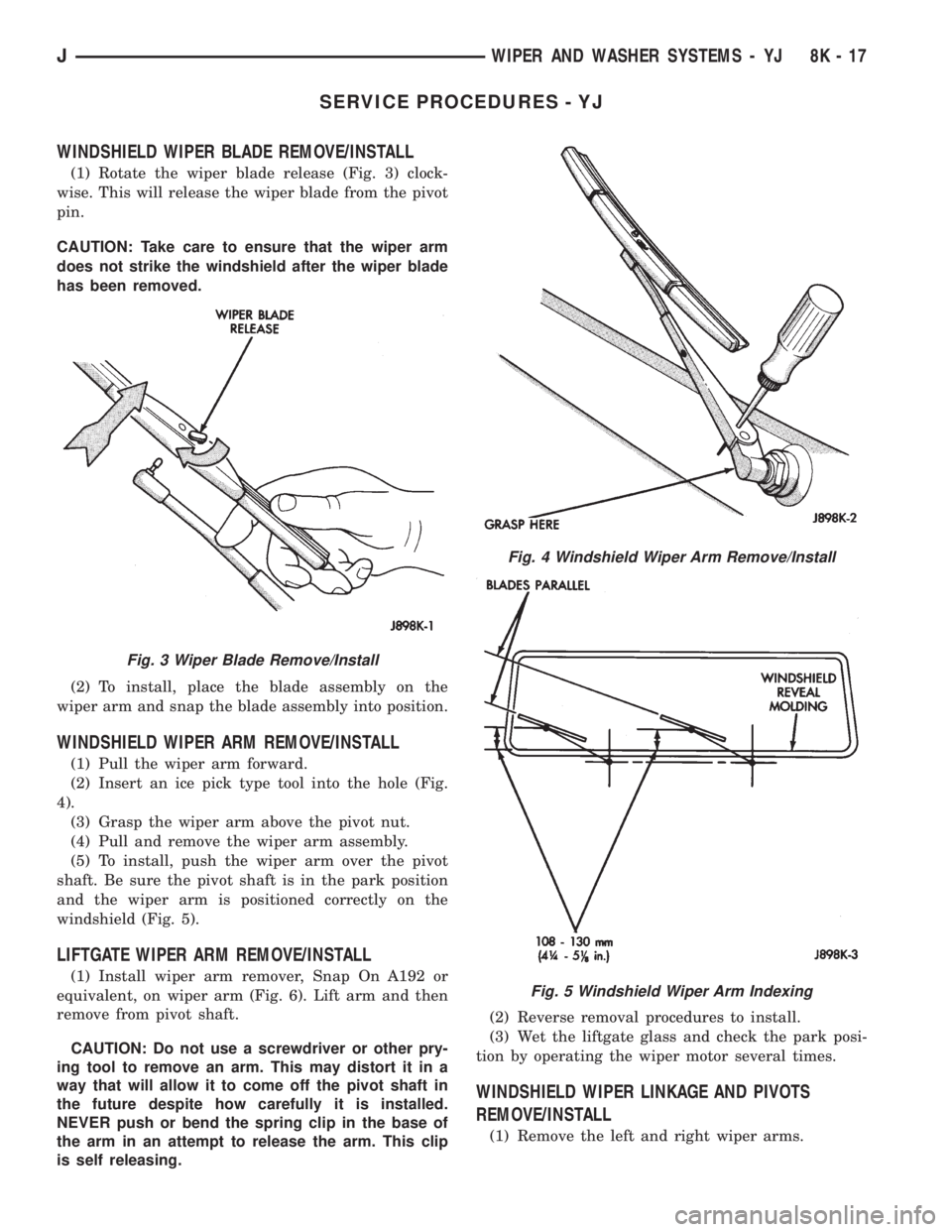
WINDSHIELD WIPER BLADE REMOVE/INSTALL
(1) Rotate the wiper blade release (Fig. 3) clock-
wise. This will release the wiper blade from the pivot
pin.
CAUTION: Take care to ensure that the wiper arm
does not strike the windshield after the wiper blade
has been removed.
(2) To install, place the blade assembly on the
wiper arm and snap the blade assembly into position.
WINDSHIELD WIPER ARM REMOVE/INSTALL
(1) Pull the wiper arm forward.
(2) Insert an ice pick type tool into the hole (Fig.
4).
(3) Grasp the wiper arm above the pivot nut.
(4) Pull and remove the wiper arm assembly.
(5) To install, push the wiper arm over the pivot
shaft. Be sure the pivot shaft is in the park position
and the wiper arm is positioned correctly on the
windshield (Fig. 5).
LIFTGATE WIPER ARM REMOVE/INSTALL
(1) Install wiper arm remover, Snap On A192 or
equivalent, on wiper arm (Fig. 6). Lift arm and then
remove from pivot shaft.
CAUTION: Do not use a screwdriver or other pry-
ing tool to remove an arm. This may distort it in a
way that will allow it to come off the pivot shaft in
the future despite how carefully it is installed.
NEVER push or bend the spring clip in the base of
the arm in an attempt to release the arm. This clip
is self releasing.(2) Reverse removal procedures to install.
(3) Wet the liftgate glass and check the park posi-
tion by operating the wiper motor several times.
WINDSHIELD WIPER LINKAGE AND PIVOTS
REMOVE/INSTALL
(1) Remove the left and right wiper arms.
Fig. 3 Wiper Blade Remove/Install
Fig. 4 Windshield Wiper Arm Remove/Install
Fig. 5 Windshield Wiper Arm Indexing
JWIPER AND WASHER SYSTEMS - YJ 8K - 17
Page 501 of 2158

POWER LOCKS
CONTENTS
page page
DIAGNOSIS............................. 2
GENERAL INFORMATION.................. 1SERVICE PROCEDURES................... 8
GENERAL INFORMATION
Power locks are optional equipment on XJ (Chero-
kee) models. Power windows and the keyless entry
system are included on vehicles equipped with the
power lock option. All doors and the liftgate can be
locked and unlocked electrically by operating the
switch on either front door panel, or by operating the
lock and unlock buttons of the remote keyless entry
transmitter. The power lock and keyless entry sys-
tems operate with battery power supplied indepen-
dent of the ignition switch.
Following are general descriptions of the major
components in the power lock system. Refer to Group
8W - Wiring Diagrams for complete circuit descrip-
tions and diagrams. Refer to the owner's manual for
more information on the features and use of these
systems.
POWER LOCK SWITCH
The power locks are controlled by a two-way switch
mounted on the trim panel of each front door. The
switch controls battery feed to the lock and unlock
relays. The door lock switches can not be repaired. If
faulty, the entire switch must be replaced.
POWER LOCK/UNLOCK RELAYS
The power lock and unlock relays are located in the
relay center. The relay center is located on the lower
instrument panel reinforcement behind the lower in-
strument panel and just right of the steering column.
The relays respond to inputs from the power lock
switches and the keyless entry module by sending
the correct battery and ground feeds to the lock mo-
tors. The lock and unlock relays can not be repaired.
If faulty, they must be replaced.
POWER LOCK MOTOR
The locks are actuated by a reversible motor
mounted within each door. The motor direction iscontrolled by the battery and ground feeds from the
power lock/unlock relays. The motor can not be re-
paired. If faulty, the entire motor must be replaced.
KEYLESS ENTRY TRANSMITTER
The keyless entry transmitter is equipped with two
buttons labeled Lock and Unlock. It is also designed
to serve as a key fob and is equipped with a key ring.
Each transmitter has a different vehicle access code,
which must be programmed into the memory of the
keyless entry module in the vehicle in order to oper-
ate the locks. The operating range of the infrared
transmitter signal is up to 4.75 meters (15 feet) from
the receiver.
The transmitter operates on two CR1616 3-volt (or
equivalent) batteries. Typical battery life is from one
to two years.
KEYLESS ENTRY MODULE
The keyless entry module is mounted in a housing
on the headliner near the windshield between the
sunvisors, or inside and towards the rear of the over-
head console (if equipped). This module contains the
keyless entry receiver and program logic for the key-
less entry system.
The keyless entry module has a memory function
to retain the vehicle access code of at least one, and
up to four transmitters. The module receives input
from the remote keyless entry transmitter. In re-
sponse to that input, it is programmed to control out-
puts to the lock and unlock relays. The module can
not be repaired and, if faulty, must be replaced.
JPOWER LOCKS 8P - 1
Page 535 of 2158
WIRING DIAGRAMSÐGENERAL INFORMATION
INDEX
page page
Circuit Identification......................... 1
Connector and Terminal Replacement........... 7
Connector Replacement..................... 6
Connectors............................... 2
Diode Replacement........................ 8
Electrostatic Discharge (ESC) Sensitive Devices . . . 2
General Information......................... 1
Intermittent and Poor Connections.............. 4
Notes, Cautions, and Warnings................ 1Symbols................................. 2
Take Outs................................ 2
Terminal Replacement....................... 8
Terminal/Connector RepairÐMolex Connectors.... 6
Troubleshooting Tests....................... 4
Troubleshooting Tools....................... 4
Troubleshooting Wiring Problems.............. 5
Wire Code Identification..................... 1
Wiring Repair............................. 6
GENERAL INFORMATION
This Group is divided into three stand alone sec-
tions; XJ, YJ, and XJ Right Hand Drive (XJ-RHD).
Separate circuit descriptions and wiring diagrams are
provided for each vehicle. Each section contains a
Contents list for the wiring diagrams and circuit de-
scriptions for that vehicle.
The complete XJ circuit descriptions and diagrams
are printed first, followed by those for the YJ and
then the XJ-RHD. The heading at the top of each
page identifies the vehicle covered in the section.
NOTES, CAUTIONS, and WARNINGS
Throughout this group additional important infor-
mation is presented in three ways; Notes, Cautions,
and Warnings.
NOTESare used to help describe how switches or
components operate to complete a particular circuit.
They are also used to indicate different conditions
that may appear on the vehicle. For example, an
up-to and after condition.
CAUTIONSare used to indicate information that
could prevent making an error that may damage the
vehicle.
WARNINGSprovide information to prevent per-
sonal injury and vehicle damage. Below is a list of
general warnings that should be followed any time a
vehicle is being serviced.
ALWAYS WEAR SAFETY GLASSES FOR EYE PRO-
TECTION.
USE SAFETY STANDS ANYTIME A PROCEDURE RE-
QUIRES BEING UNDER A VEHICLE.
BE SURE THAT THE IGNITION SWITCH ALWAYS IS
IN THE OFF POSITION, UNLESS THE PROCEDURE
REQUIRES IT TO BE ON.SET THE PARKING BRAKE WHEN WORKING ON
ANY VEHICLE. AN AUTOMATIC TRANSMISSION
SHOULD BE IN PARK. A MANUAL TRANSMISSION
SHOULD BE IN NEUTRAL.
OPERATE THE ENGINE ONLY IN A WELL-VENTI-
LATED AREA.
KEEP AWAY FROM MOVING PARTS WHEN THE EN-
GINE IS RUNNING, ESPECIALLY THE FAN AND BELTS.
TO PREVENT SERIOUS BURNS, AVOID CONTACT
WITH HOT PARTS SUCH AS THE RADIATOR, EX-
HAUST MANIFOLD(S), TAIL PIPE, CATALYTIC CON-
VERTER, AND MUFFLER.
DO NOT ALLOW FLAME OR SPARKS NEAR THE
BATTERY. GASES ARE ALWAYS PRESENT IN AND
AROUND THE BATTERY.
ALWAYS REMOVE RINGS, WATCHES, LOOSE
HANGING JEWELRY, AND LOOSE CLOTHING.
WIRE CODE IDENTIFICATION
Each wire shown in the diagrams contains a code
(Fig. 1) which identifies the main circuit, part of the
main circuit, gauge of wire, and color. The color is
shown as a two letter code which can be identified by
referring to the Wire Color Code Chart (Fig. 2).
CIRCUIT IDENTIFICATION
All circuits in the diagrams use an alpha/numeric
code to identify the wire and its function (Fig. 3). To
identify which circuit code applies to a system, refer
to the Circuit Identification Code Chart. This chart
shows the main circuits only and does not show the
secondary codes that may apply to some models.
JWIRING DIAGRAMSÐGENERAL INFORMATION 8W - 1
Page 1286 of 2158
filter runoff, and main bearing cap to cylinder
block mating surfaces. See Group 9, Engines for
proper repair procedures of these items.
(4) If no leaks are detected, pressurized the crank-
case as outlined in the, Inspection (Engine oil Leaks
in general)
CAUTION: Do not exceed 20.6 kPa (3 psi).
(5) If the leak is not detected, very slowly turn the
crankshaft and watch for leakage. If a leak is de-
tected between the crankshaft and seal while slowly
turning the crankshaft, it is possible the crankshaft
seal surface is damaged. The seal area on the crank-
shaft could have minor nicks or scratches that can be
polished out with emery cloth.
CAUTION: Use extreme caution when crankshaft
polishing is necessary to remove minor nicks and
scratches. The crankshaft seal flange is especially
machined to complement the function of the rear oil
seal.(6) For bubbles that remain steady with shaft ro-
tation, no further inspection can be done until disas-
sembled. Refer to the service DiagnosisÐMechanical,
under the Oil Leak row for components inspections
on possible causes and corrections.
(7) After the oil leak root cause and appropriate
corrective action have been identified, Refer to Group
9, EnginesÐCrankshaft Rear Oil Seals, for proper re-
placement procedures.
ENGINE OIL PRESSURE
(1) Remove oil pressure sending unit.
(2) Install Oil Pressure Line and Gauge Tool
C-3292. Start engine and record pressure. Refer to
Oil Pressure in Engine Specifications for the proper
pressures.
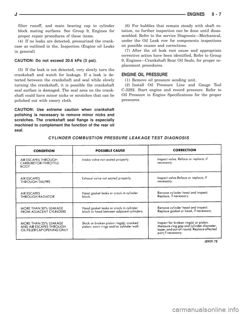
CYLINDER COMBUSTION PRESSURE LEAKAGE TEST DIAGNOSIS
JENGINES 9 - 7
Page 1302 of 2158
(3) Connect the CCV hoses (Fig. 1).
(4) Connect negative cable to battery.
VALVE COMPONENT REPLACEÐCYLINDER HEAD
NOT REMOVED
ROCKER ARMS AND PUSH RODS
This procedure can be done with the engine in or
out of the vehicle.
REMOVAL
(1) Remove the engine cylinder head cover.
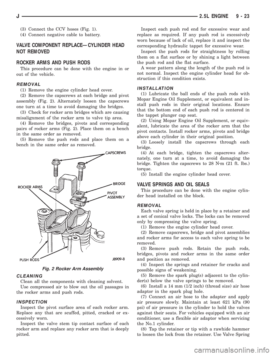
(2) Remove the capscrews at each bridge and pivot
assembly (Fig. 2). Alternately loosen the capscrews
one turn at a time to avoid damaging the bridges.
(3) Check for rocker arm bridges which are causing
misalignment of the rocker arm to valve tip area.
(4) Remove the bridges, pivots and corresponding
pairs of rocker arms (Fig. 2). Place them on a bench
in the same order as removed.
(5) Remove the push rods and place them on a
bench in the same order as removed.
CLEANING
Clean all the components with cleaning solvent.
Use compressed air to blow out the oil passages in
the rocker arms and push rods.
INSPECTION
Inspect the pivot surface area of each rocker arm.
Replace any that are scuffed, pitted, cracked or ex-
cessively worn.
Inspect the valve stem tip contact surface of each
rocker arm and replace any rocker arm that is deeply
pitted.Inspect each push rod end for excessive wear and
replace as required. If any push rod is excessively
worn because of lack of oil, replace it and inspect the
corresponding hydraulic tappet for excessive wear.
Inspect the push rods for straightness by rolling
them on a flat surface or by shining a light between
the push rod and the flat surface.
A wear pattern along the length of the push rod is
not normal. Inspect the engine cylinder head for ob-
struction if this condition exists.
INSTALLATION
(1) Lubricate the ball ends of the push rods with
Mopar Engine Oil Supplement, or equivalent and in-
stall push rods in their original locations. Ensure
that the bottom end of each push rod is centered in
the tappet plunger cap seat.
(2) Using Mopar Engine Oil Supplement, or equiv-
alent, lubricate the area of the rocker arm that the
pivot contacts. Install rocker arms, pivots and bridge
above each cylinder in their original position.
(3) Loosely install the capscrews through each
bridge.
(4) At each bridge, tighten the capscrews alter-
nately, one turn at a time, to avoid damaging the
bridge. Tighten the capscrews to 28 Nzm (21 ft. lbs.)
torque.
(5) Install the engine cylinder head cover.
VALVE SPRINGS AND OIL SEALS
This procedure can be done with the engine cylin-
der head installed on the block.
REMOVAL
Each valve spring is held in place by a retainer and
a set of conical valve locks. The locks can be removed
only by compressing the valve spring.
(1) Remove the engine cylinder head cover.
(2) Remove capscrews, bridge and pivot assemblies
and rocker arms for access to each valve spring to be
removed.
(3) Remove push rods. Retain the push rods,
bridges, pivots and rocker arms in the same order
and position as removed.
(4) Inspect the springs and retainer for cracks and
possible signs of weakening.
(5) Remove the spark plug(s) adjacent to the cylin-
der(s) below the valve springs to be removed.
(6) Install a 14 mm (1/2 inch) (thread size) air hose
adaptor in the spark plug hole.
(7) Connect an air hose to the adapter and apply
air pressure slowly. Maintain at least 621 kPa (90
psi) of air pressure in the cylinder to hold the valves
against their seats. For vehicles equipped with an air
conditioner, use a flexible air adaptor when servicing
the No.1 cylinder.
(8) Tap the retainer or tip with a rawhide hammer
to loosen the lock from the retainer. Use Valve Spring
Fig. 2 Rocker Arm Assembly
J2.5L ENGINE 9 - 23
Page 1303 of 2158
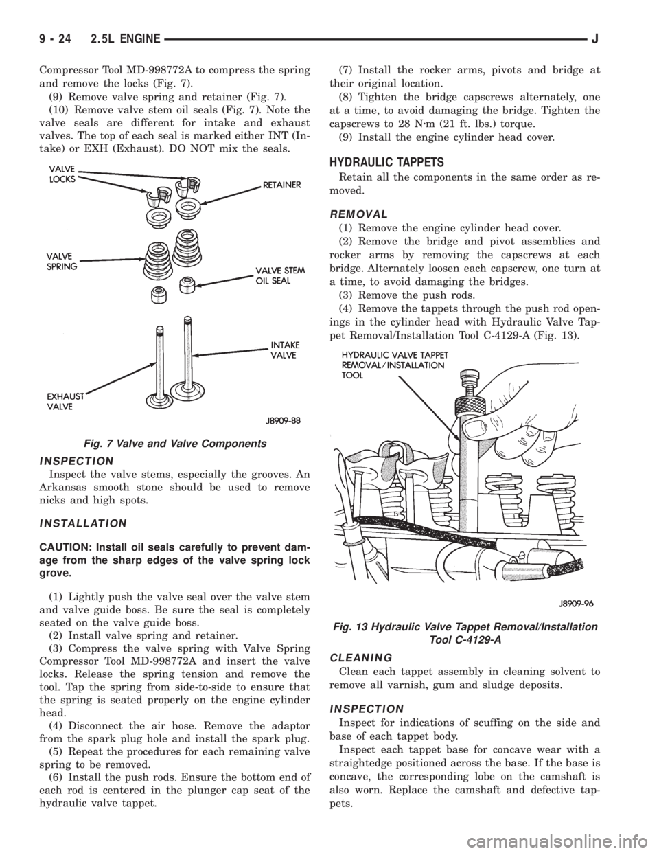
Compressor Tool MD-998772A to compress the spring
and remove the locks (Fig. 7).
(9) Remove valve spring and retainer (Fig. 7).
(10) Remove valve stem oil seals (Fig. 7). Note the
valve seals are different for intake and exhaust
valves. The top of each seal is marked either INT (In-
take) or EXH (Exhaust). DO NOT mix the seals.
INSPECTION
Inspect the valve stems, especially the grooves. An
Arkansas smooth stone should be used to remove
nicks and high spots.
INSTALLATION
CAUTION: Install oil seals carefully to prevent dam-
age from the sharp edges of the valve spring lock
grove.
(1) Lightly push the valve seal over the valve stem
and valve guide boss. Be sure the seal is completely
seated on the valve guide boss.
(2) Install valve spring and retainer.
(3) Compress the valve spring with Valve Spring
Compressor Tool MD-998772A and insert the valve
locks. Release the spring tension and remove the
tool. Tap the spring from side-to-side to ensure that
the spring is seated properly on the engine cylinder
head.
(4) Disconnect the air hose. Remove the adaptor
from the spark plug hole and install the spark plug.
(5) Repeat the procedures for each remaining valve
spring to be removed.
(6) Install the push rods. Ensure the bottom end of
each rod is centered in the plunger cap seat of the
hydraulic valve tappet.(7) Install the rocker arms, pivots and bridge at
their original location.
(8) Tighten the bridge capscrews alternately, one
at a time, to avoid damaging the bridge. Tighten the
capscrews to 28 Nzm (21 ft. lbs.) torque.
(9) Install the engine cylinder head cover.
HYDRAULIC TAPPETS
Retain all the components in the same order as re-
moved.
REMOVAL
(1) Remove the engine cylinder head cover.
(2) Remove the bridge and pivot assemblies and
rocker arms by removing the capscrews at each
bridge. Alternately loosen each capscrew, one turn at
a time, to avoid damaging the bridges.
(3) Remove the push rods.
(4) Remove the tappets through the push rod open-
ings in the cylinder head with Hydraulic Valve Tap-
pet Removal/Installation Tool C-4129-A (Fig. 13).
CLEANING
Clean each tappet assembly in cleaning solvent to
remove all varnish, gum and sludge deposits.
INSPECTION
Inspect for indications of scuffing on the side and
base of each tappet body.
Inspect each tappet base for concave wear with a
straightedge positioned across the base. If the base is
concave, the corresponding lobe on the camshaft is
also worn. Replace the camshaft and defective tap-
pets.
Fig. 7 Valve and Valve Components
Fig. 13 Hydraulic Valve Tappet Removal/Installation
Tool C-4129-A
9 - 24 2.5L ENGINEJ
Page 1307 of 2158
(2) Use Valve Spring Compressor Tool
MD-998772A and compress each valve spring.
(3) Remove the valve locks, retainers, springs and
valve stem oil seals. Discard the oil seals.
(4) Use an Arkansas smooth stone or a jewelers
file to remove any burrs on the top of the valve stem,
especially around the groove for the locks.
(5) Remove the valves, and place them in a rack in
the same order as removed.
VALVE CLEANING
Clean all carbon deposits from the combustion
chambers, valve ports, valve stems, valve stem
guides and head.
Clean all grime and gasket material from the en-
gine cylinder head machined gasket surface.
INSPECTION
Inspect for cracks in the combustion chambers and
valve ports.
Inspect for cracks on the exhaust seat.
Inspect for cracks in the gasket surface at each
coolant passage.
Inspect valves for burned, cracked or warped
heads.
Inspect for scuffed or bent valve stems.
Replace valves displaying any damage.
VALVE REFACING
(1) Use a valve refacing machine to reface the in-
take and exhaust valves to the specified angle.
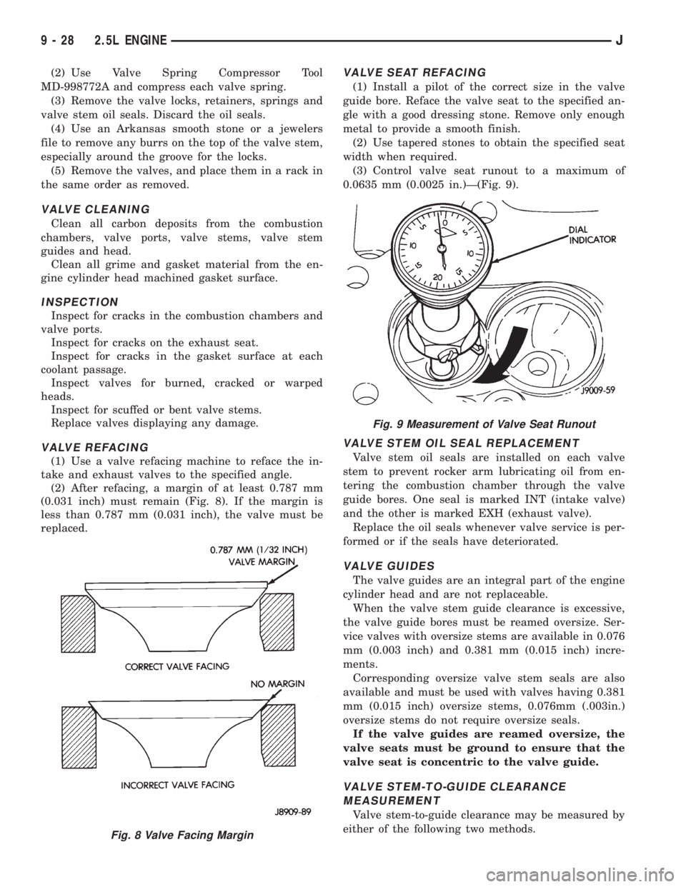
(2) After refacing, a margin of at least 0.787 mm
(0.031 inch) must remain (Fig. 8). If the margin is
less than 0.787 mm (0.031 inch), the valve must be
replaced.
VALVE SEAT REFACING
(1) Install a pilot of the correct size in the valve
guide bore. Reface the valve seat to the specified an-
gle with a good dressing stone. Remove only enough
metal to provide a smooth finish.
(2) Use tapered stones to obtain the specified seat
width when required.
(3) Control valve seat runout to a maximum of
0.0635 mm (0.0025 in.)Ð(Fig. 9).
VALVE STEM OIL SEAL REPLACEMENT
Valve stem oil seals are installed on each valve
stem to prevent rocker arm lubricating oil from en-
tering the combustion chamber through the valve
guide bores. One seal is marked INT (intake valve)
and the other is marked EXH (exhaust valve).
Replace the oil seals whenever valve service is per-
formed or if the seals have deteriorated.
VALVE GUIDES
The valve guides are an integral part of the engine
cylinder head and are not replaceable.
When the valve stem guide clearance is excessive,
the valve guide bores must be reamed oversize. Ser-
vice valves with oversize stems are available in 0.076
mm (0.003 inch) and 0.381 mm (0.015 inch) incre-
ments.
Corresponding oversize valve stem seals are also
available and must be used with valves having 0.381
mm (0.015 inch) oversize stems, 0.076mm (.003in.)
oversize stems do not require oversize seals.
If the valve guides are reamed oversize, the
valve seats must be ground to ensure that the
valve seat is concentric to the valve guide.
VALVE STEM-TO-GUIDE CLEARANCE
MEASUREMENT
Valve stem-to-guide clearance may be measured by
either of the following two methods.
Fig. 8 Valve Facing Margin
Fig. 9 Measurement of Valve Seat Runout
9 - 28 2.5L ENGINEJ