1995 JEEP YJ ESP
[x] Cancel search: ESPPage 1365 of 2158
(10) Using a ring installer, install the top ring with
the chamfer facing up (Fig. 16). The dot will be fac-
ing up.
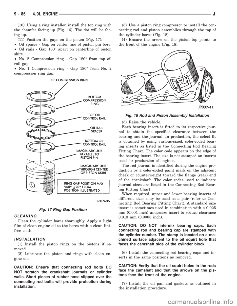
(11) Position the gaps on the piston (Fig. 17):
²Oil spacer - Gap on center line of piston pin bore.
²Oil rails - Gap 180É apart on centerline of piston
skirt.
²No. 2 Compression ring - Gap 180É from top oil
rail gap.
²No. 1 Compression ring - Gap 180É from No. 2
compression ring gap.
CLEANING
Clean the cylinder bores thoroughly. Apply a light
film of clean engine oil to the bores with a clean lint-
free cloth.
INSTALLATION
(1) Install the piston rings on the pistons if re-
moved.
(2) Lubricate the piston and rings with clean en-
gine oil.
CAUTION: Ensure that connecting rod bolts DO
NOT scratch the crankshaft journals or cylinder
walls. Short pieces of rubber hose slipped over the
connecting rod bolts will provide protection during
installation.(3) Use a piston ring compressor to install the con-
necting rod and piston assemblies through the top of
the cylinder bores (Fig. 18).
(4) Ensure the arrow on the piston top points to
the front of the engine (Fig. 18).
(5) Raise the vehicle.
Each bearing insert is fitted to its respective jour-
nal to obtain the specified clearance between the
bearing and the journal. In production, the select fit
is obtained by using various-sized, color-coded bear-
ing inserts as listed in the Connecting Rod Bearing
Fitting Chart. The color code appears on the edge of
the bearing insert. The size is not stamped on inserts
used for production of engines.
The rod journal is identified during the engine pro-
duction by a color-coded paint mark on the adjacent
cheek or counterweight toward the flange (rear) end
of the crankshaft. The color codes used to indicate
journal sizes are listed in the Connecting Rod Bear-
ing Fitting Chart.
When required, upper and lower bearing inserts of
different sizes may be used as a pair (refer to Con-
necting Rod Bearing Fitting Chart). A standard size
insert is sometimes used in combination with a 0.025
mm (0.001 inch) undersize insert to reduce clearance
0.013 mm (0.0005 inch).
CAUTION: DO NOT intermix bearing caps. Each
connecting rod and bearing cap are stamped with
the cylinder number. The stamp is located on a ma-
chined surface adjacent to the oil squirt hole that
faces the camshaft side of the cylinder block.
(6) Install the connecting rod bearing caps and in-
serts in the same positions as removed.
CAUTION: Verify that the oil squirt holes in the rods
face the camshaft and that the arrows on the pis-
tons face the front of the engine.
(7) Install the oil pan and gaskets as outlined in
the installation procedure.
Fig. 17 Ring Gap Position
Fig. 18 Rod and Piston Assembly Installation
9 - 86 4.0L ENGINEJ
Page 1367 of 2158
ward position. The upper main bearing inserts are
grooved to provide oil channels while the lower in-
serts are smooth.
Each bearing insert pair is selectively fitted to its
respective journal to obtain the specified operating
clearance. In production, the select fit is obtained by
using various-sized color-coded bearing insert pairs
as listed in the Main Bearing Fitting Chart. The
bearing color code appears on the edge of the insert.
The size is not stamped on bearing inserts used
for engine production.
The main bearing journal size (diameter) is identi-
fied by a color-coded paint mark on the adjacent
cheek. The rear main journal, is identified by a color-
coded paint mark on the crankshaft rear flange.
When required, upper and lower bearing inserts of
different sizes may be used as a pair. A standard size
insert is sometimes used in combination with a 0.025
mm (0.001 inch) undersize insert to reduce the clear-
ance by 0.013 mm (0.0005 inch).Never use a pair
of bearing inserts with greater than a 0.025 mm
(0.001 inch) difference in size (Fig. 4).
When replacing inserts, the odd size inserts
must be either all on the top (in cylinder block)
or all on the bottom (in main bearing cap).
Once the bearings have been properly fitted, pro-
ceed to Crankshaft Main BearingÐInstallation.
BEARING-TO-JOURNAL CLEARANCE (CRANKSHAFT
INSTALLED)
When using Plastigage, check only one bearing
clearance at a time.
Install the grooved main bearings into the cylinder
block and the non-grooved bearings into the bearing
caps.
Install the crankshaft into the upper bearings dry.
Place a strip of Plastigage across full width of the
crankshaft journal to be checked.
Install the bearing cap and tighten the bolts to 108
Nzm (80 ft. lbs.) torque.
DO NOT rotate the crankshaft. This will
cause the Plastigage to shift, resulting in an in-
accurate reading. Plastigage must not be per-
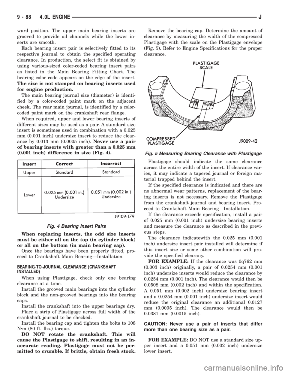
mitted to crumble. If brittle, obtain fresh stock.Remove the bearing cap. Determine the amount of
clearance by measuring the width of the compressed
Plastigage with the scale on the Plastigage envelope
(Fig. 5). Refer to Engine Specifications for the proper
clearance.
Plastigage should indicate the same clearance
across the entire width of the insert. If clearance var-
ies, it may indicate a tapered journal or foreign ma-
terial trapped behind the insert.
If the specified clearance is indicated and there are
no abnormal wear patterns, replacement of the bear-
ing inserts is not necessary. Remove the Plastigage
from the crankshaft journal and bearing insert. Pro-
ceed to Crankshaft Main BearingÐInstallation.
If the clearance exceeds specification, install a pair
of 0.025 mm (0.001 inch) undersize bearing inserts
and measure the clearance as described in the previ-
ous steps.
The clearance indicatewith the 0.025 mm (0.001
inch) undersize insert pair installed will determine if
this insert size or some other combination will pro-
vide the specified clearany.
FOR EXAMPLE:If the clearance was 0q762 mm
(0.003 inch) originally, a pair of 0.0254 mm (0.001
inch) undersize inserts would reduce the clearance by
0.0254 mm (0.001 inch). The clearance would then be
0.0508 mm (0.002 inch) and within the specification.
A 0.051 mm (0.002 inch) undersize bearing insert
and a 0.0254 mm (0.001 inch) undersize insert would
reduce the original clearance an additional 0.0127
mm (0.0005 inch). The clearance would then be
0.0381 mm (0.0015 inch).
CAUTION: Never use a pair of inserts that differ
more than one bearing size as a pair.
FOR EXAMPLE:DO NOT use a standard size up-
per insert and a 0.051 mm (0.002 inch) undersize
lower insert.
Fig. 4 Bearing Insert Pairs
Fig. 5 Measuring Bearing Clearance with Plastigage
9 - 88 4.0L ENGINEJ
Page 1404 of 2158
line. You may encounter fuels containing 3 percent or
more methanol along with other alcohols called cosol-
vents.
Problems that are the result of using methanol/gas-
oline blends are not the responsibility of Chrysler
Corporation. They may not be covered by the vehicle
warranty.
MTBE/ETBE
Gasoline and MTBE (Methyl Tertiary Butyl Ether)
blends are a mixture of unleaded gasoline and up to
15 percent MTBE. Gasoline and ETBE (Ethyl Ter-
tiary Butyl Ether) are blends of gasoline and up to
17 percent ETBE. Gasoline blended with MTBE or
ETBE may be used in your vehicle.CLEAN AIR GASOLINE
Many gasolines are now being blended that con-
tribute to cleaner air, especially in those areas of the
country where air pollution levels are high. These
new blends provide a cleaner burning fuel and some
are referred to asReformulated Gasoline.
In areas of the country where carbon monoxide lev-
els are high, gasolines are being treated with oxygen-
ated materials such as MTBE, ETBE and ethanol.
Chrysler Corporation supports these efforts toward
cleaner air and recommends that you use these gaso-
lines as they become available.
14 - 2 FUEL SYSTEMJ
Page 1424 of 2158
energized). This is done to compensate for the re-
duced flow through injector caused by the lowered
voltage.
BRAKE SWITCHÐPCM INPUT
When the brake light switch is activated, the pow-
ertrain control module (PCM) receives an input indi-
cating that the brakes are being applied. After
receiving this input, the PCM maintains idle speed to
a scheduled rpm through control of the idle air con-
trol (IAC) motor. The brake switch input is also used
to operate the speed control system.
CAMSHAFT POSITION SENSORÐPCM INPUT
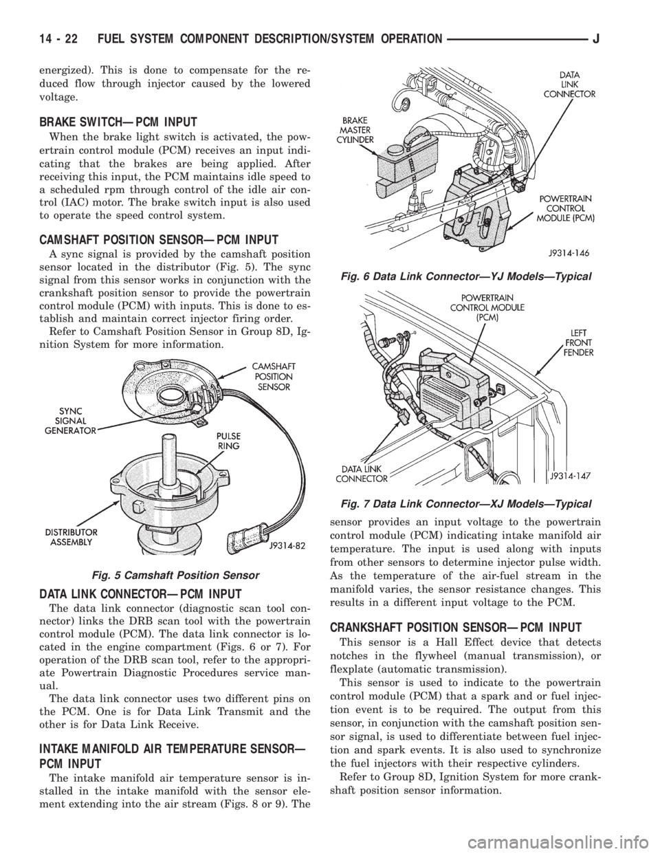
A sync signal is provided by the camshaft position
sensor located in the distributor (Fig. 5). The sync
signal from this sensor works in conjunction with the
crankshaft position sensor to provide the powertrain
control module (PCM) with inputs. This is done to es-
tablish and maintain correct injector firing order.
Refer to Camshaft Position Sensor in Group 8D, Ig-
nition System for more information.
DATA LINK CONNECTORÐPCM INPUT
The data link connector (diagnostic scan tool con-
nector) links the DRB scan tool with the powertrain
control module (PCM). The data link connector is lo-
cated in the engine compartment (Figs. 6 or 7). For
operation of the DRB scan tool, refer to the appropri-
ate Powertrain Diagnostic Procedures service man-
ual.
The data link connector uses two different pins on
the PCM. One is for Data Link Transmit and the
other is for Data Link Receive.
INTAKE MANIFOLD AIR TEMPERATURE SENSORÐ
PCM INPUT
The intake manifold air temperature sensor is in-
stalled in the intake manifold with the sensor ele-
ment extending into the air stream (Figs. 8 or 9). Thesensor provides an input voltage to the powertrain
control module (PCM) indicating intake manifold air
temperature. The input is used along with inputs
from other sensors to determine injector pulse width.
As the temperature of the air-fuel stream in the
manifold varies, the sensor resistance changes. This
results in a different input voltage to the PCM.
CRANKSHAFT POSITION SENSORÐPCM INPUT
This sensor is a Hall Effect device that detects
notches in the flywheel (manual transmission), or
flexplate (automatic transmission).
This sensor is used to indicate to the powertrain
control module (PCM) that a spark and or fuel injec-
tion event is to be required. The output from this
sensor, in conjunction with the camshaft position sen-
sor signal, is used to differentiate between fuel injec-
tion and spark events. It is also used to synchronize
the fuel injectors with their respective cylinders.
Refer to Group 8D, Ignition System for more crank-
shaft position sensor information.
Fig. 5 Camshaft Position Sensor
Fig. 6 Data Link ConnectorÐYJ ModelsÐTypical
Fig. 7 Data Link ConnectorÐXJ ModelsÐTypical
14 - 22 FUEL SYSTEM COMPONENT DESCRIPTION/SYSTEM OPERATIONJ
Page 1426 of 2158
The MAP sensor is mounted on the dash panel.
The sensor is connected to the throttle body with a
vacuum hose and to the PCM electrically.
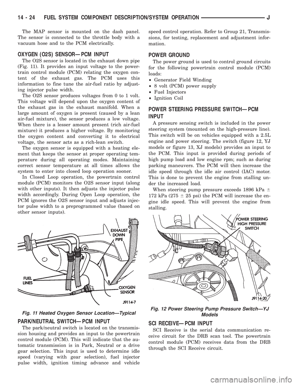
OXYGEN (O2S) SENSORÐPCM INPUT
The O2S sensor is located in the exhaust down pipe
(Fig. 11). It provides an input voltage to the power-
train control module (PCM) relating the oxygen con-
tent of the exhaust gas. The PCM uses this
information to fine tune the air-fuel ratio by adjust-
ing injector pulse width.
The O2S sensor produces voltages from 0 to 1 volt.
This voltage will depend upon the oxygen content of
the exhaust gas in the exhaust manifold. When a
large amount of oxygen is present (caused by a lean
air-fuel mixture), the sensor produces a low voltage.
When there is a lesser amount present (rich air-fuel
mixture) it produces a higher voltage. By monitoring
the oxygen content and converting it to electrical
voltage, the sensor acts as a rich-lean switch.
The oxygen sensor is equipped with a heating ele-
ment that keeps the sensor at proper operating tem-
perature during all operating modes. Maintaining
correct sensor temperature at all times allows the
system to enter into closed loop operation sooner.
In Closed Loop operation, the powertrain control
module (PCM) monitors the O2S sensor input (along
with other inputs). It then adjusts the injector pulse
width accordingly. During Open Loop operation, the
PCM ignores the O2S sensor input and adjusts injec-
tor pulse width to a preprogrammed value (based on
other sensor inputs).
PARK/NEUTRAL SWITCHÐPCM INPUT
The park/neutral switch is located on the transmis-
sion housing and provides an input to the powertrain
control module (PCM). This will indicate that the au-
tomatic transmission is in Park, Neutral or a drive
gear selection. This input is used to determine idle
speed (varying with gear selection), fuel injector
pulse width, ignition timing advance and vehiclespeed control operation. Refer to Group 21, Transmis-
sions, for testing, replacement and adjustment infor-
mation.
POWER GROUND
The power ground is used to control ground circuits
for the following powertrain control module (PCM)
loads:
²Generator Field Winding
²8 volt (PCM) power supply
²Fuel Injectors
²Ignition Coil
POWER STEERING PRESSURE SWITCHÐPCM
INPUT
A pressure sensing switch is included in the power
steering system (mounted on the high-pressure line).
This switch will be on vehicles equipped with a 2.5L
engine and power steering. The switch (figure 12, YJ
models or figure 13, XJ models) provides an input to
the PCM. This input is provided during periods of
high pump load and low engine rpm; such as during
parking maneuvers. The PCM will then increase the
idle speed through the idle air control (IAC) motor.
This is done to prevent the engine from stalling un-
der the increased load.
When steering pump pressure exceeds 1896 kPa6
172 kPa (275625 psi) the PCM will increase the en-
gine idle speed. This will prevent the engine from
stalling.
SCI RECEIVEÐPCM INPUT
SCI Receive is the serial data communication re-
ceive circuit for the DRB scan tool. The powertrain
control module (PCM) receives data from the DRB
through the SCI Receive circuit.
Fig. 11 Heated Oxygen Sensor LocationÐTypicalFig. 12 Power Steering Pump Pressure SwitchÐYJ
Models
14 - 24 FUEL SYSTEM COMPONENT DESCRIPTION/SYSTEM OPERATIONJ
Page 1427 of 2158
SPEED CONTROLÐPCM INPUT
The speed control system provides three separate
inputs to the powertrain control module (PCM); On/
Off, Set and Resume. The On/Off input informs the
PCM that the speed control system has been acti-
vated. The Set input informs the PCM that a fixed
vehicle speed has been selected. The Resume input
indicates to the PCM that the previous fixed speed is
requested.
The speed control operating range is from 50 km/h
to 142 km/h (35 to 85 mph). Inputs that effect speed
control operation are:
²Brake switch position
²Park/neutral switch
²Vehicle speed sensor
²Throttle position sensor
Refer to Group 8H for further speed control infor-
mation.
SENSOR RETURNÐPCM INPUT
Sensor Return provides a low noise ground refer-
ence for all system sensors.
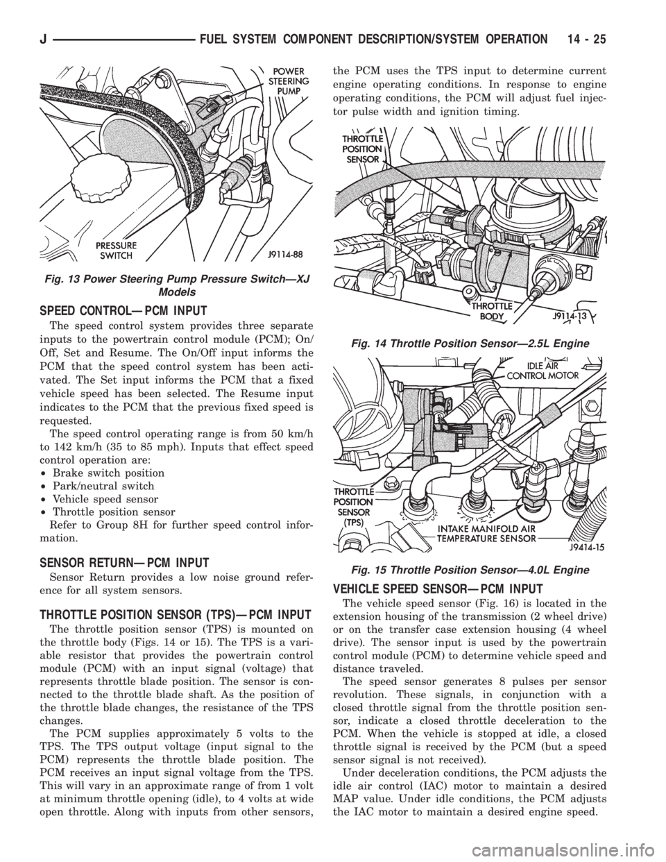
THROTTLE POSITION SENSOR (TPS)ÐPCM INPUT
The throttle position sensor (TPS) is mounted on
the throttle body (Figs. 14 or 15). The TPS is a vari-
able resistor that provides the powertrain control
module (PCM) with an input signal (voltage) that
represents throttle blade position. The sensor is con-
nected to the throttle blade shaft. As the position of
the throttle blade changes, the resistance of the TPS
changes.
The PCM supplies approximately 5 volts to the
TPS. The TPS output voltage (input signal to the
PCM) represents the throttle blade position. The
PCM receives an input signal voltage from the TPS.
This will vary in an approximate range of from 1 volt
at minimum throttle opening (idle), to 4 volts at wide
open throttle. Along with inputs from other sensors,the PCM uses the TPS input to determine current
engine operating conditions. In response to engine
operating conditions, the PCM will adjust fuel injec-
tor pulse width and ignition timing.
VEHICLE SPEED SENSORÐPCM INPUT
The vehicle speed sensor (Fig. 16) is located in the
extension housing of the transmission (2 wheel drive)
or on the transfer case extension housing (4 wheel
drive). The sensor input is used by the powertrain
control module (PCM) to determine vehicle speed and
distance traveled.
The speed sensor generates 8 pulses per sensor
revolution. These signals, in conjunction with a
closed throttle signal from the throttle position sen-
sor, indicate a closed throttle deceleration to the
PCM. When the vehicle is stopped at idle, a closed
throttle signal is received by the PCM (but a speed
sensor signal is not received).
Under deceleration conditions, the PCM adjusts the
idle air control (IAC) motor to maintain a desired
MAP value. Under idle conditions, the PCM adjusts
the IAC motor to maintain a desired engine speed.
Fig. 13 Power Steering Pump Pressure SwitchÐXJ
Models
Fig. 14 Throttle Position SensorÐ2.5L Engine
Fig. 15 Throttle Position SensorÐ4.0L Engine
JFUEL SYSTEM COMPONENT DESCRIPTION/SYSTEM OPERATION 14 - 25
Page 1432 of 2158
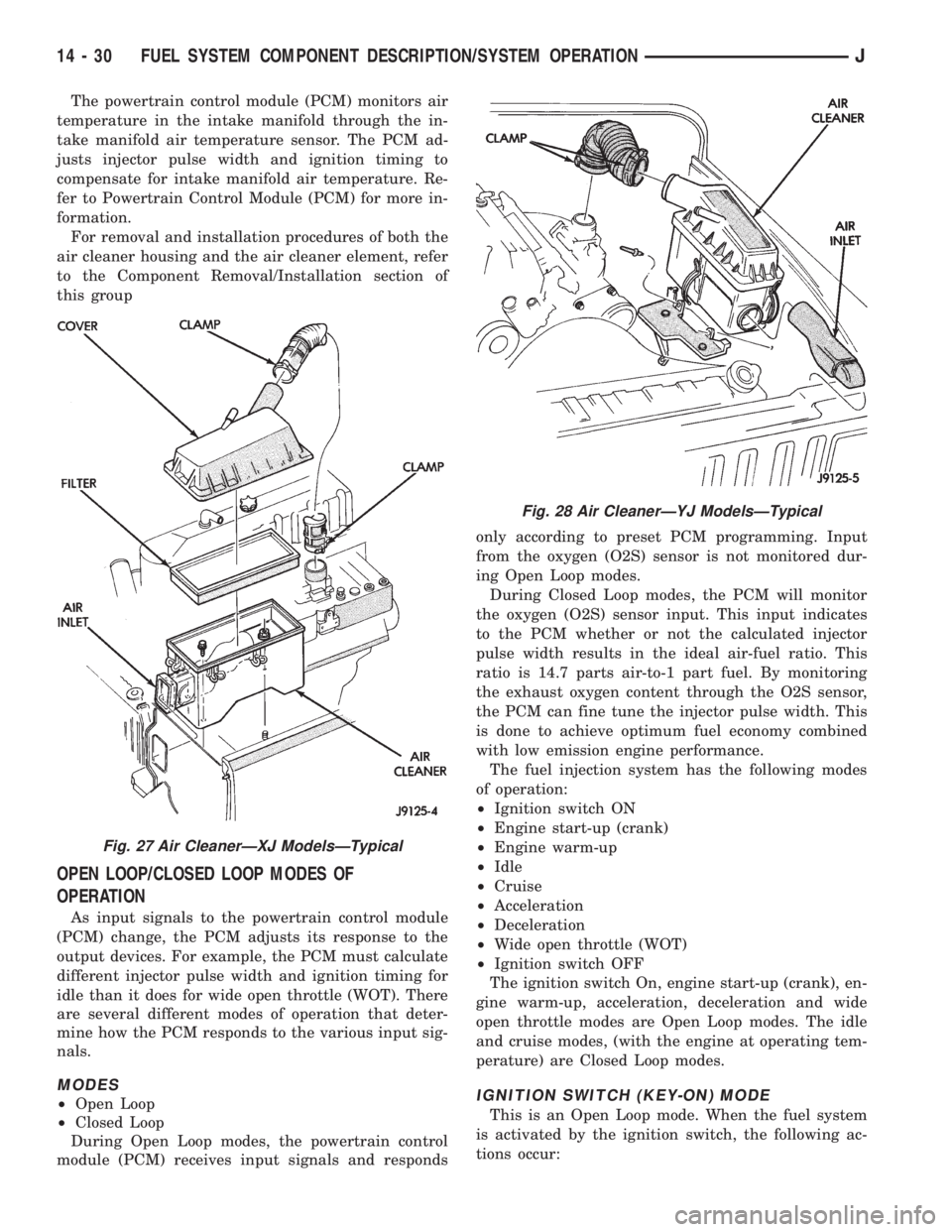
The powertrain control module (PCM) monitors air
temperature in the intake manifold through the in-
take manifold air temperature sensor. The PCM ad-
justs injector pulse width and ignition timing to
compensate for intake manifold air temperature. Re-
fer to Powertrain Control Module (PCM) for more in-
formation.
For removal and installation procedures of both the
air cleaner housing and the air cleaner element, refer
to the Component Removal/Installation section of
this group
OPEN LOOP/CLOSED LOOP MODES OF
OPERATION
As input signals to the powertrain control module
(PCM) change, the PCM adjusts its response to the
output devices. For example, the PCM must calculate
different injector pulse width and ignition timing for
idle than it does for wide open throttle (WOT). There
are several different modes of operation that deter-
mine how the PCM responds to the various input sig-
nals.
MODES
²Open Loop
²Closed Loop
During Open Loop modes, the powertrain control
module (PCM) receives input signals and respondsonly according to preset PCM programming. Input
from the oxygen (O2S) sensor is not monitored dur-
ing Open Loop modes.
During Closed Loop modes, the PCM will monitor
the oxygen (O2S) sensor input. This input indicates
to the PCM whether or not the calculated injector
pulse width results in the ideal air-fuel ratio. This
ratio is 14.7 parts air-to-1 part fuel. By monitoring
the exhaust oxygen content through the O2S sensor,
the PCM can fine tune the injector pulse width. This
is done to achieve optimum fuel economy combined
with low emission engine performance.
The fuel injection system has the following modes
of operation:
²Ignition switch ON
²Engine start-up (crank)
²Engine warm-up
²Idle
²Cruise
²Acceleration
²Deceleration
²Wide open throttle (WOT)
²Ignition switch OFF
The ignition switch On, engine start-up (crank), en-
gine warm-up, acceleration, deceleration and wide
open throttle modes are Open Loop modes. The idle
and cruise modes, (with the engine at operating tem-
perature) are Closed Loop modes.IGNITION SWITCH (KEY-ON) MODE
This is an Open Loop mode. When the fuel system
is activated by the ignition switch, the following ac-
tions occur:
Fig. 27 Air CleanerÐXJ ModelsÐTypical
Fig. 28 Air CleanerÐYJ ModelsÐTypical
14 - 30 FUEL SYSTEM COMPONENT DESCRIPTION/SYSTEM OPERATIONJ
Page 1434 of 2158
²The PCM adjusts ignition timing by increasing
and decreasing spark advance.
²The PCM operates the A/C compressor clutch
through the clutch relay. This happens if A/C has
been selected by the vehicle operator and requested
by the A/C thermostat.
The optional Extended Idle Switch is used to raise
the engine idle speed to approximately 1000 rpm.
This is when the shifter is in either the Park or Neu-
tral position. A rocker-type 2-wire switch (extended
idle switch) is mounted to the instrument panel. This
switch will supply a ground circuit to the powertrain
control module (PCM).The switch is available
only with 4.0L engine when supplied with the
optional police package.
CRUISE MODE
When the engine is at operating temperature, this
is a Closed Loop mode. At cruising speed, the power-
train control module (PCM) receives inputs from:
²Air conditioning select signal (if equipped)
²Air conditioning request signal (if equipped)
²Battery voltage
²Engine coolant temperature sensor
²Crankshaft position sensor
²Intake manifold air temperature sensor
²Manifold absolute pressure (MAP) sensor
²Throttle position sensor (TPS)
²Camshaft position sensor signal (in the distribu-
tor)
²Park/neutral switch (gear indicator signalÐauto.
trans. only)
²Oxygen (O2S) sensor
Based on these inputs, the following occurs:
²Voltage is applied to the fuel injectors with the
PCM. The PCM will then adjust the injector pulse
width by turning the ground circuit to each individ-
ual injector on and off.
²The PCM monitors the O2S sensor input and ad-
justs air-fuel ratio. It also adjusts engine idle speed
through the idle air control (IAC) motor.
²The PCM adjusts ignition timing by turning the
ground path to the coil on and off.
²The PCM operates the A/C compressor clutch
through the clutch relay. This happens if A/C has
been selected by the vehicle operator and requested
by the A/C thermostat.
ACCELERATION MODE
This is an Open Loop mode. The powertrain control
module (PCM) recognizes an abrupt increase in
throttle position or MAP pressure as a demand for
increased engine output and vehicle acceleration. The
PCM increases injector pulse width in response to in-
creased throttle opening.
DECELERATION MODE
When the engine is at operating temperature, this
is an Open Loop mode. During hard deceleration, the
powertrain control module (PCM) receives the follow-
ing inputs.
²Air conditioning select signal (if equipped)
²Air conditioning request signal (if equipped)
²Battery voltage
²Engine coolant temperature sensor
²Crankshaft position sensor
²Intake manifold air temperature sensor
²Manifold absolute pressure (MAP) sensor
²Throttle position sensor (TPS)
²Camshaft position sensor signal (in the distribu-
tor)
²Park/neutral switch (gear indicator signalÐauto.
trans. only)
If the vehicle is under hard deceleration with the
proper rpm and closed throttle conditions, the PCM
will ignore the oxygen sensor input signal. The PCM
will enter a fuel cut-off strategy in which it will not
supply battery voltage to the injectors. If a hard de-
celeration does not exist, the PCM will determine the
proper injector pulse width and continue injection.
Based on the above inputs, the PCM will adjust en-
gine idle speed through the idle air control (IAC) mo-
tor.
The PCM adjusts ignition timing by turning the
ground path to the coil on and off.
The PCM opens the ground circuit to the A/C
clutch relay to disengage the A/C compressor clutch.
This is done until the vehicle is no longer under de-
celeration (if the A/C system is operating).
WIDE OPEN THROTTLE MODE
This is an Open Loop mode. During wide open
throttle operation, the powertrain control module
(PCM) receives the following inputs.
²Battery voltage
²Crankshaft position sensor
²Engine coolant temperature sensor
²Intake manifold air temperature sensor
²Manifold absolute pressure (MAP) sensor
²Throttle position sensor (TPS)
²Camshaft position sensor signal (in the distribu-
tor)
During wide open throttle conditions, the following
occurs:
²Voltage is applied to the fuel injectors with the
powertrain control module (PCM). The PCM will
then control the injection sequence and injector pulse
width by turning the ground circuit to each individ-
ual injector on and off. The PCM ignores the oxygen
sensor input signal and provides a predetermined
amount of additional fuel. This is done by adjusting
injector pulse width.
²The PCM adjusts ignition timing by turning the
ground path to the coil on and off.
14 - 32 FUEL SYSTEM COMPONENT DESCRIPTION/SYSTEM OPERATIONJ