1995 JEEP YJ transmission
[x] Cancel search: transmissionPage 1850 of 2158
(14) Pull transfer case and jack rearward to disen-
gage transfer case.
(15) Remove transfer case from under vehicle.
(16) If transfer case was removed for overhaul, re-
move damper from rear retainer.
TRANSFER CASE INSTALLATION
(1) Mount transfer case on a transmission jack. Se-
cure transfer case to jack with chains.
(2) Position transfer case under vehicle.(3) Align transfer case and transmission shafts and
install transfer case on transmission.
(4) Install and tighten transfer case attaching nuts
to 35 Nzm (26 ft. lbs.) torque.
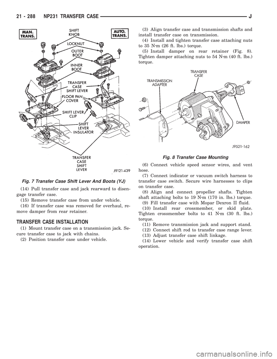
(5) Install damper on rear retainer (Fig. 8).
Tighten damper attaching nuts to 54 Nzm (40 ft. lbs.)
torque.
(6) Connect vehicle speed sensor wires, and vent
hose.
(7) Connect indicator or vacuum switch harness to
transfer case switch. Secure wire harnesses to clips
on transfer case.
(8) Align and connect propeller shafts. Tighten
shaft attaching bolts to 19 Nzm (170 in. lbs.) torque.
(9) Fill transfer case with Mopar Dexron II fluid.
(10) Install rear crossmember, or skid plate.
Tighten crossmember bolts to 41 Nzm (30 ft. lbs.)
torque.
(11) Remove transmission jack and support stand.
(12) Connect shift rod to transfer case range lever.
(13) Adjust transfer case shift linkage.
(14) Lower vehicle and verify transfer case shift
operation.
Fig. 7 Transfer Case Shift Lever And Boots (YJ)
Fig. 8 Transfer Case Mounting
21 - 288 NP231 TRANSFER CASEJ
Page 1862 of 2158
MAINSHAFT ASSEMBLY
(1) If drive sprocket bearings are to be replaced,
remove and install them as follows:
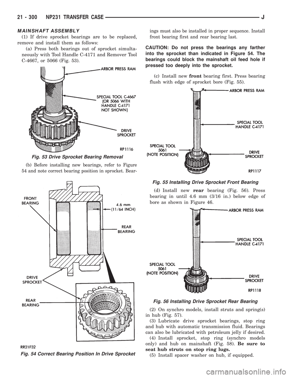
(a) Press both bearings out of sprocket simulta-
neously with Tool Handle C-4171 and Remover Tool
C-4667, or 5066 (Fig. 53).
(b) Before installing new bearings, refer to Figure
54 and note correct bearing position in sprocket. Bear-ings must also be installed in proper sequence. Install
front bearing first and rear bearing last.
CAUTION: Do not press the bearings any farther
into the sprocket than indicated in Figure 54. The
bearings could block the mainshaft oil feed hole if
pressed too deeply into the sprocket.
(c) Install newfrontbearing first. Press bearing
flush with edge of sprocket bore (Fig. 55).
(d) Install newrearbearing (Fig. 56). Press
bearing in until 4.6 mm (3/16 in.) below edge of
bore as shown in Figure 46.
(2) On synchro models, install struts and spring(s)
in hub (Fig. 57).
(3) Lubricate drive sprocket bearings, stop ring
and hub with automatic transmission fluid. Bearings
can also be lubricated with petroleum jelly if desired.
(4) Install sprocket, stop ring (synchro models
only) and hub on mainshaft (Fig. 58).Be sure to
seat hub struts on stop ring lugs.
(5) Install spacer washer on hub, if equipped.
Fig. 54 Correct Bearing Position In Drive Sprocket
Fig. 53 Drive Sprocket Bearing Removal
Fig. 55 Installing Drive Sprocket Front Bearing
Fig. 56 Installing Drive Sprocket Rear Bearing
21 - 300 NP231 TRANSFER CASEJ
Page 1864 of 2158
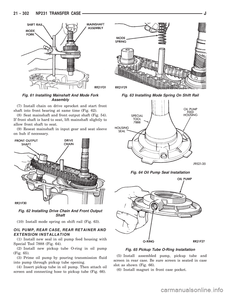
(7) Install chain on drive sprocket and start front
shaft into front bearing at same time (Fig. 62).
(8) Seat mainshaft and front output shaft (Fig. 54).
If front shaft is hard to seat, lift mainshaft slightly to
allow front shaft to seat.
(9) Reseat mainshaft in input gear and seat sleeve
on hub if necessary.
(10) Install mode spring on shift rail (Fig. 63).
OIL PUMP, REAR CASE, REAR RETAINER AND
EXTENSION INSTALLATION
(1) Install new seal in oil pump feed housing with
Special Tool 7888 (Fig. 64).
(2) Install new pickup tube O-ring in oil pump
(Fig. 65).
(3) Prime oil pump by pouring transmission fluid
into pump through pickup tube opening.
(4) Insert pickup tube in oil pump. Then attach oil
screen and connecting hose to pickup tube (Fig. 66).(5) Install assembled pump, pickup tube and
screen in rear case. Be sure screen is seated in case
slot as shown (Fig. 66).
(6) Install magnet in front case pocket.
Fig. 61 Installing Mainshaft And Mode Fork
Assembly
Fig. 62 Installing Drive Chain And Front Output
Shaft
Fig. 63 Installing Mode Spring On Shift Rail
Fig. 64 Oil Pump Seal Installation
Fig. 65 Pickup Tube O-Ring Installation
21 - 302 NP231 TRANSFER CASEJ
Page 1871 of 2158
SHIFT LINKAGE ADJUSTMENT
(1) Shift transfer case into 4L position.
(2) Raise vehicle.
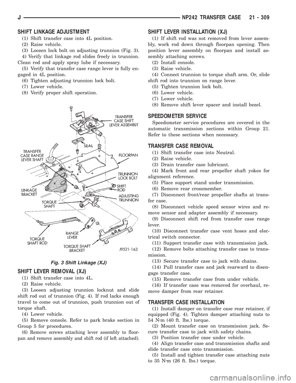
(3) Loosen lock bolt on adjusting trunnion (Fig. 3).
4) Verify that linkage rod slides freely in trunnion.
Clean rod and apply spray lube if necessary.
(5) Verify that transfer case range lever is fully en-
gaged in 4L position.
(6) Tighten adjusting trunnion lock bolt.
(7) Lower vehicle.
(8) Verify proper shift operation.
SHIFT LEVER REMOVAL (XJ)
(1) Shift transfer case into 4L.
(2) Raise vehicle.
(3) Loosen adjusting trunnion locknut and slide
shift rod out of trunnion (Fig. 4). If rod lacks enough
travel to come out of trunnion, push trunnion out of
torque shaft.
(4) Lower vehicle.
(5) Remove console. Refer to park brake section in
Group 5 for procedures.
(6) Remove screws attaching lever assembly to floor-
pan and remove assembly and shift rod (if left attached).
SHIFT LEVER INSTALLATION (XJ)
(1) If shift rod was not removed from lever assem-
bly, work rod down through floorpan opening. Then
position lever assembly on floorpan and install as-
sembly attaching screws.
(2) Install console.
(3) Raise vehicle.
(4) Connect trunnion to torque shaft arm. Or, slide
shift rod into trunnion on range lever.
(5) Tighten trunnion lock bolt.
(6) Lower vehicle.
(7) Lower vehicle.
(8) Remove shift lever spacer and install bezel.
SPEEDOMETER SERVICE
Speedometer service procedures are covered in the
automatic transmission sections within Group 21.
Refer to these sections when necessary.
TRANSFER CASE REMOVAL
(1) Shift transfer case into Neutral.
(2) Raise vehicle.
(3) Drain transfer case lubricant.
(4) Mark front and rear propeller shaft yokes for
alignment reference.
(5) Place support stand under transmission.
(6) Remove rear crossmember.
(7) Disconnect front/rear propeller shafts at trans-
fer case.
(8) Disconnect vehicle speed sensor wires and re-
move sensor and adapter assembly if necessary.
(9) Disconnect shift rod from transfer case range
lever.
(10) Disconnect transfer case vent hoses and elec-
trical switch connector.
(11) Support transfer case with transmission jack.
(12) Remove bolts attaching transfer case to trans-
mission.
(13) Secure transfer case to jack with chains.
(14) Pull transfer case and jack rearward to disen-
gage transfer case.
(15) Remove transfer case from under vehicle.
(16) If transfer case was removed for overhaul, re-
move damper from rear retainer.
TRANSFER CASE INSTALLATION
(1) Install damper on transfer case rear retainer, if
equipped (Fig. 4). Tighten damper attaching nuts to
54 Nzm (40 ft. lbs.) torque.
(2) Mount transfer case on transmission jack. Se-
cure transfer case to jack with safety chains.
(3) Position transfer case under vehicle.
(4) Align transfer case and transmission shafts and
slide transfer case onto transmission.
(5) Install and tighten transfer case attaching nuts
to 35 Nzm (26 ft. lbs.) torque.
Fig. 3 Shift Linkage (XJ)
JNP242 TRANSFER CASE 21 - 309
Page 1872 of 2158
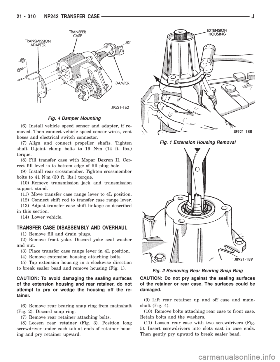
(6) Install vehicle speed sensor and adapter, if re-
moved. Then connect vehicle speed sensor wires, vent
hoses and electrical switch connector.
(7) Align and connect propeller shafts. Tighten
shaft U-joint clamp bolts to 19 Nzm (14 ft. lbs.)
torque.
(8) Fill transfer case with Mopar Dexron II. Cor-
rect fill level is to bottom edge of fill plug hole.
(9) Install rear crossmember. Tighten crossmember
bolts to 41 Nzm (30 ft. lbs.) torque.
(10) Remove transmission jack and transmission
support stand.
(11) Move transfer case range lever to 4L position.
(12) Connect shift rod to transfer case range lever.
(13) Adjust transfer case shift linkage as described
in this section.
(14) Lower vehicle.
TRANSFER CASE DISASSEMBLY AND OVERHAUL
(1) Remove fill and drain plugs.
(2) Remove front yoke. Discard yoke seal washer
and nut.
(3) Place transfer case range lever in 4L position.
(4) Remove extension housing attaching bolts.
(5) Tap extension housing in a clockwise direction
to break sealer bead and remove housing (Fig. 1).
CAUTION: To avoid damaging the sealing surfaces
of the extension housing and rear retainer, do not
attempt to pry or wedge the housing off the re-
tainer.
(6) Remove rear bearing snap ring from mainshaft
(Fig. 2). Discard snap ring.
(7) Remove rear retainer attaching bolts.
(8) Loosen rear retainer (Fig. 3). Position long
screwdriver under each tab at ends of retainer hous-
ing and pry retainer upward.CAUTION: Do not pry against the sealing surfaces
of the retainer or rear case. The surfaces could be
damaged.
(9) Lift rear retainer up and off case and main-
shaft (Fig. 4).
(10) Remove bolts attaching rear case to front case.
Retain bolts and the washers.
(11) Loosen rear case with two screwdrivers (Fig.
5). Insert screwdrivers into slots cast in case ends.
Then gently pry upward to break sealer bead.
Fig. 4 Damper Mounting
Fig. 1 Extension Housing Removal
Fig. 2 Removing Rear Bearing Snap Ring
21 - 310 NP242 TRANSFER CASEJ
Page 1881 of 2158
Inspect the differential gears, thrust washers and
case halves. Replace the mainshaft gear if the gear
teeth or the brass ring on the underside of the gear
are damaged. Replace the differential as an assembly
if the gears, case halves, or the pins in the lower case
half are damaged.
Inspect the case halves, extension housing and re-
tainers for cracks, porosity, or damaged sealing sur-
faces. Inspect the shafts, gears, chain and shift
components for wear or damage.
Inspect all of the transfer case bearings for wear,
roughness, pitting, or galling. Replace worn or dam-
aged bearings as outlined in the assembly section.
TRANSFER CASE ASSEMBLY
(1) Lubricate transfer case components with auto-
matic transmission fluid or petroleum jelly (where in-
dicated) during assembly.
CAUTION: The bearing bores in various transfer
case components contain oil feed holes. Be sure re-
placement bearings do not block these feed holes.
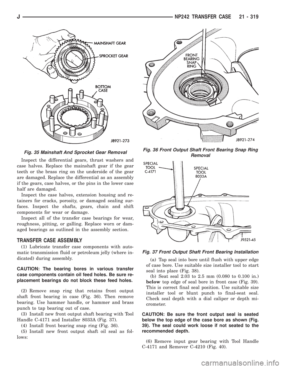
(2) Remove snap ring that retains front output
shaft front bearing in case (Fig. 36). Then remove
bearing. Use hammer handle, or hammer and brass
punch to tap bearing out of case.
(3) Install new front output shaft bearing with Tool
Handle C-4171 and Installer 8033A (Fig. 37).
(4) Install front bearing snap ring (Fig. 36).
(5) Install new front output shaft oil seal as fol-
lows:(a) Tap seal into bore until flush with upper edge
of case bore. Use suitable size installer tool to start
seal into place (Fig. 38).
(b) Seat seal 2.03 to 2.5 mm (0.080 to 0.100 in.)
belowtop edge of seal bore in front case (Fig. 39).
This is correct final seal position. Use suitable size
installer tool or blunt punch to final-seat seal.
Check seal depth with a dial caliper or depth mi-
crometer.
CAUTION: Be sure the front output seal is seated
below the top edge of the case bore as shown (Fig.
39). The seal could work loose if not seated to the
recommended depth.
(6) Remove input gear bearing with Tool Handle
C-4171 and Remover C-4210 (Fig. 40).
Fig. 35 Mainshaft And Sprocket Gear RemovalFig. 36 Front Output Shaft Front Bearing Snap Ring
Removal
Fig. 37 Front Output Shaft Front Bearing Installation
JNP242 TRANSFER CASE 21 - 319
Page 1883 of 2158
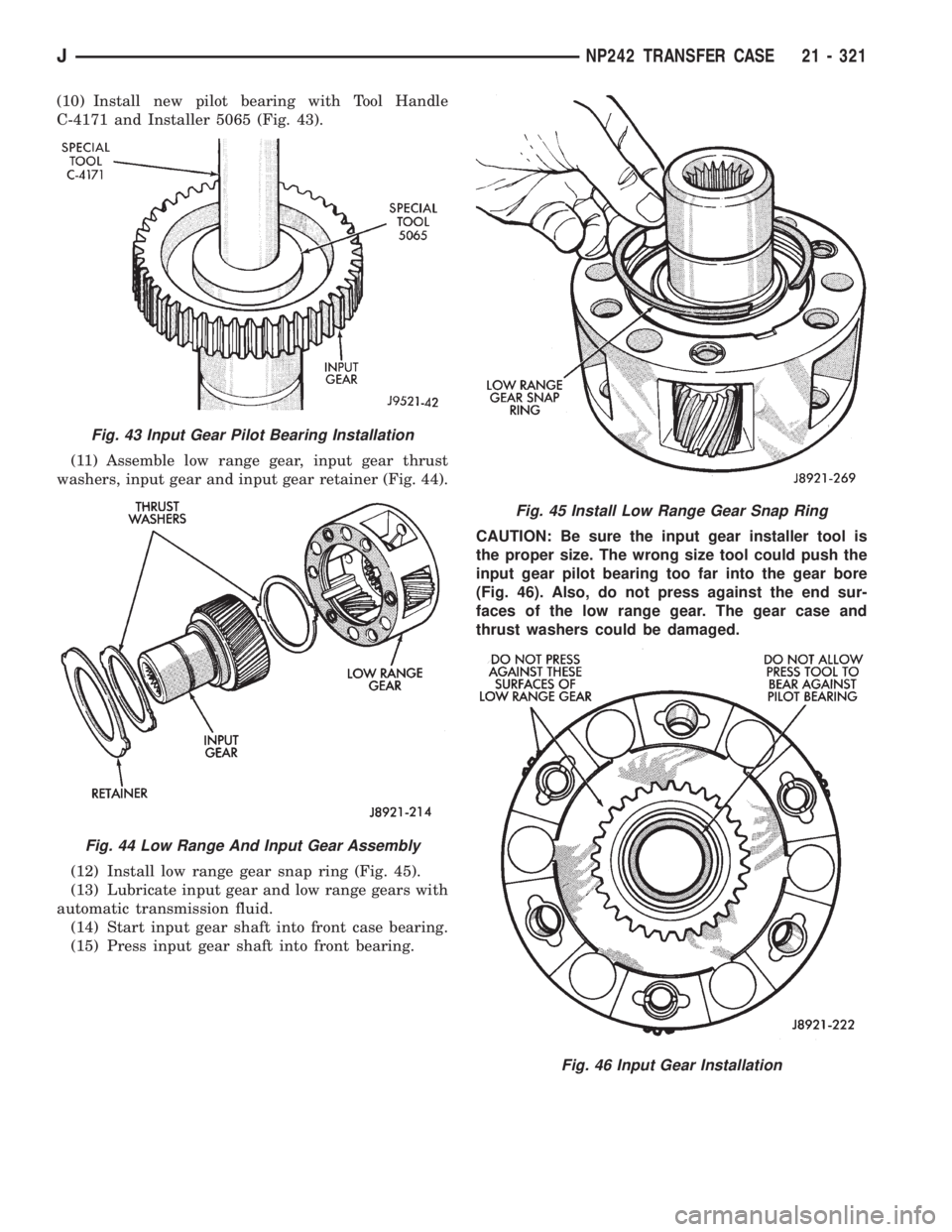
(10) Install new pilot bearing with Tool Handle
C-4171 and Installer 5065 (Fig. 43).
(11) Assemble low range gear, input gear thrust
washers, input gear and input gear retainer (Fig. 44).
(12) Install low range gear snap ring (Fig. 45).
(13) Lubricate input gear and low range gears with
automatic transmission fluid.
(14) Start input gear shaft into front case bearing.
(15) Press input gear shaft into front bearing.CAUTION: Be sure the input gear installer tool is
the proper size. The wrong size tool could push the
input gear pilot bearing too far into the gear bore
(Fig. 46). Also, do not press against the end sur-
faces of the low range gear. The gear case and
thrust washers could be damaged.
Fig. 43 Input Gear Pilot Bearing Installation
Fig. 44 Low Range And Input Gear Assembly
Fig. 45 Install Low Range Gear Snap Ring
Fig. 46 Input Gear Installation
JNP242 TRANSFER CASE 21 - 321
Page 1885 of 2158
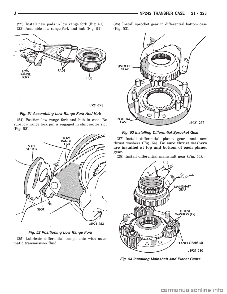
(22) Install new pads in low range fork (Fig. 51).
(23) Assemble low range fork and hub (Fig. 51).
(24) Position low range fork and hub in case. Be
sure low range fork pin is engaged in shift sector slot
(Fig. 52).
(25) Lubricate differential components with auto-
matic transmission fluid.(26) Install sprocket gear in differential bottom case
(Fig. 53).
(27) Install differential planet gears and new
thrust washers (Fig. 54).Be sure thrust washers
are installed at top and bottom of each planet
gear.
(28) Install differential mainshaft gear (Fig. 54).
Fig. 51 Assembling Low Range Fork And Hub
Fig. 52 Positioning Low Range Fork
Fig. 53 Installing Differential Sprocket Gear
Fig. 54 Installing Mainshaft And Planet Gears
JNP242 TRANSFER CASE 21 - 323