1995 JEEP YJ speedometer
[x] Cancel search: speedometerPage 1673 of 2158
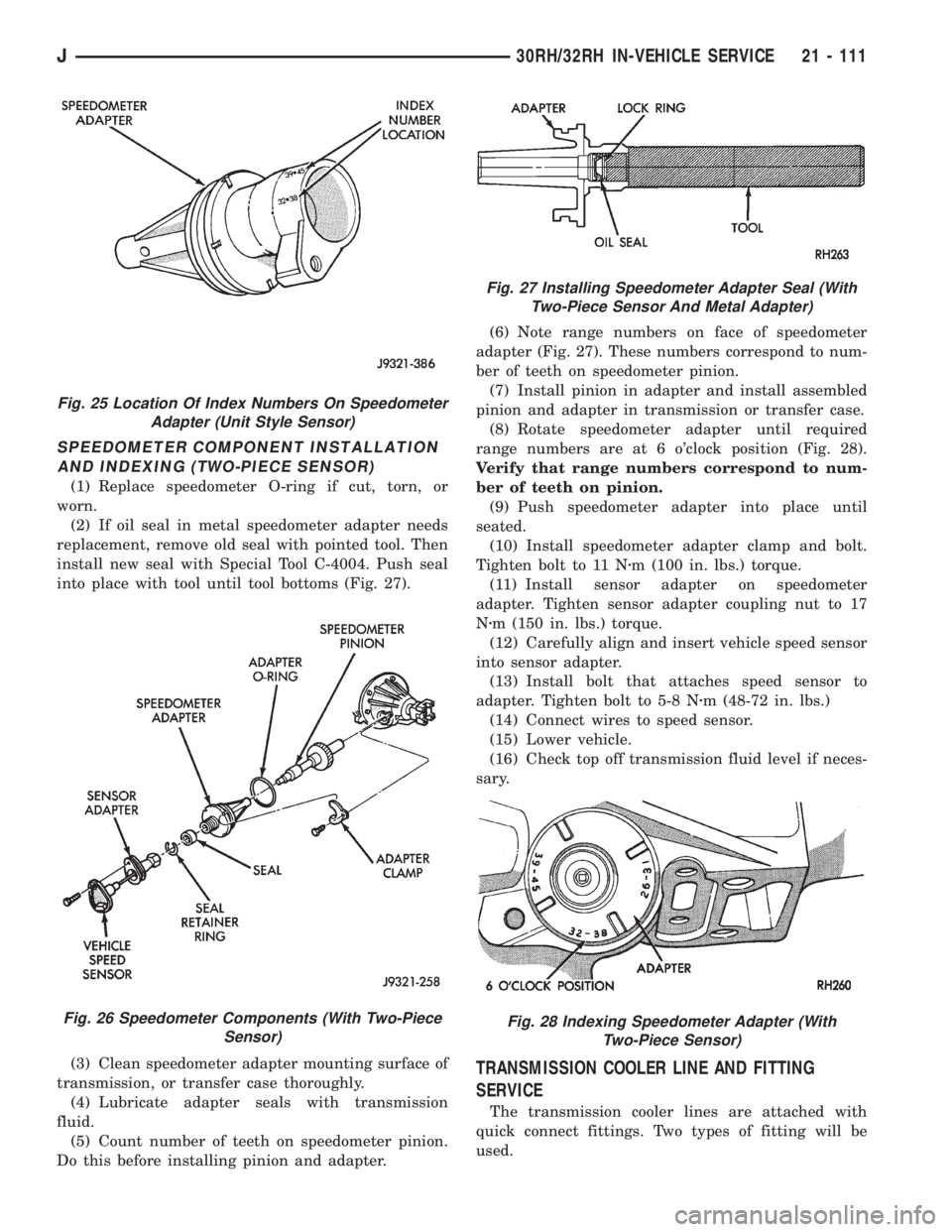
SPEEDOMETER COMPONENT INSTALLATION
AND INDEXING (TWO-PIECE SENSOR)
(1) Replace speedometer O-ring if cut, torn, or
worn.
(2) If oil seal in metal speedometer adapter needs
replacement, remove old seal with pointed tool. Then
install new seal with Special Tool C-4004. Push seal
into place with tool until tool bottoms (Fig. 27).
(3) Clean speedometer adapter mounting surface of
transmission, or transfer case thoroughly.
(4) Lubricate adapter seals with transmission
fluid.
(5) Count number of teeth on speedometer pinion.
Do this before installing pinion and adapter.(6) Note range numbers on face of speedometer
adapter (Fig. 27). These numbers correspond to num-
ber of teeth on speedometer pinion.
(7) Install pinion in adapter and install assembled
pinion and adapter in transmission or transfer case.
(8) Rotate speedometer adapter until required
range numbers are at 6 o'clock position (Fig. 28).
Verify that range numbers correspond to num-
ber of teeth on pinion.
(9) Push speedometer adapter into place until
seated.
(10) Install speedometer adapter clamp and bolt.
Tighten bolt to 11 Nzm (100 in. lbs.) torque.
(11) Install sensor adapter on speedometer
adapter. Tighten sensor adapter coupling nut to 17
Nzm (150 in. lbs.) torque.
(12) Carefully align and insert vehicle speed sensor
into sensor adapter.
(13) Install bolt that attaches speed sensor to
adapter. Tighten bolt to 5-8 Nzm (48-72 in. lbs.)
(14) Connect wires to speed sensor.
(15) Lower vehicle.
(16) Check top off transmission fluid level if neces-
sary.
TRANSMISSION COOLER LINE AND FITTING
SERVICE
The transmission cooler lines are attached with
quick connect fittings. Two types of fitting will be
used.
Fig. 25 Location Of Index Numbers On Speedometer
Adapter (Unit Style Sensor)
Fig. 26 Speedometer Components (With Two-Piece
Sensor)
Fig. 27 Installing Speedometer Adapter Seal (With
Two-Piece Sensor And Metal Adapter)
Fig. 28 Indexing Speedometer Adapter (With
Two-Piece Sensor)
J30RH/32RH IN-VEHICLE SERVICE 21 - 111
Page 1744 of 2158
AW-4 IN-VEHICLE SERVICE
INDEX
page page
Accumulator Pistons and Springs............. 189
Adapter Housing Seal Replacement........... 191
Checking Fluid Level and Condition........... 182
Manual Valve Shaft Seal Replacement......... 187
Park Interlock Cable Adjustment............. 195
Park Rod and Pawl Service................. 190
Park/Neutral Position Switch................ 183
Refilling After Overhaul or Fluid/Filter Change . . . 182
Second Coast Brake Servo................. 190
Shift Cable Adjustment.................... 195
Speed Sensor........................... 192Speed Sensor RotorÐSpeedometer Drive Gear . . 193
Throttle Position Sensor (TPS) Service........ 193
Transmission Control Module (TCM) Service.... 183
Transmission Cooler Line Fittings............ 197
Transmission Cooler Service................ 196
Transmission Throttle Cable Adjustment........ 194
Transmission Throttle Cable Replacement...... 193
Transmission Valve Body Installation.......... 187
Transmission Valve Body Removal........... 186
Transmission Valve Body Solenoids........... 184
CHECKING FLUID LEVEL AND CONDITION
Recommended fluid for AW-4 transmissions is Mo-
par Dexron IIE/Mercon.
Mopar Dexron II can also be used but only when
Mercon fluid is not available.
CHECKING FLUID LEVEL
(1) Be sure transmission fluid is at normal operat-
ing temperature. Normal operating temperature is
reached after approximately 15 miles (25 km) of op-
eration.
(2) Position vehicle on level surface. This is impor-
tant for an accurate fluid level check.
(3) Shift transmission through all gear ranges and
back to Park.
(4) Apply parking brakes.
(5) Verify that transmission is in Park.
(6) Wipe off dipstick handle to prevent dirt from
entering fill tube. Then remove dipstick and check
fluid level and condition.
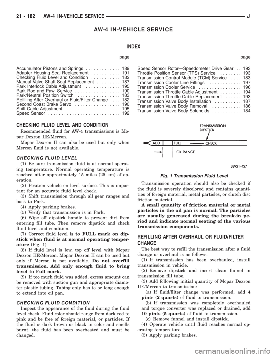
(7) Correct fluid level isto FULL mark on dip-
stick when fluid is at normal operating temper-
ature(Fig. 1).
(8) If fluid level is low, top off level with Mopar
Dexron IIE/Mercon. Mopar Dexron II can be used but
only if Mercon is not available.Do not overfill
transmission. Add only enough fluid to bring
level to Full mark.
(9) If too much fluid was added, excess amount can
be removed with suction gun and appropriate diame-
ter plastic tubing. Tubing only has to be long enough
to extend into oil pan.
CHECKING FLUID CONDITION
Inspect the appearance of the fluid during the fluid
level check. Fluid color should range from dark red to
pink and be free of foreign material, or particles. If
the fluid is dark brown or black in color and smells
burnt, the fluid has been overheated and must be
changed.Transmission operation should also be checked if
the fluid is severely discolored and contains quanti-
ties of foreign material, metal particles, or clutch disc
friction material.
A small quantity of friction material or metal
particles in the oil pan is normal. The particles
are usually generated during the break-in pe-
riod and indicate normal seating of the various
transmission components.
REFILLING AFTER OVERHAUL OR FLUID/FILTER
CHANGE
The best way to refill the transmission after a fluid
change or overhaul is as follows:
(1) If transmission has been overhauled, install
transmission in vehicle.
(2) Remove dipstick and insert clean funnel in
transmission fill tube.
(3) Add following initial quantity of Mopar Dexron
IIE/Mercon to transmission:
(a) If fluid/filter change was performed, add4
pints (2 quarts)of fluid to transmission.
(b) If transmission was completely overhauled
and torque converter was replaced or drained, add
10 pints (5 quarts)of fluid to transmission.
(c) Remove funnel and install dipstick.
(4) Operate vehicle until fluid reaches normal op-
erating temperature.
(5) Apply parking brakes.
Fig. 1 Transmission Fluid Level
21 - 182 AW-4 IN-VEHICLE SERVICEJ
Page 1755 of 2158
(4) Install new O-ring on speed sensor and install
sensor in transmission case.
(5) Install sensor bracket and retainer bolt.
Tighten bolt to 7.4 Nzm (65 in. lbs.) torque.
(6) Connect sensor wire harness connector.
SPEED SENSOR ROTORÐSPEEDOMETER DRIVE
GEAR
ROTORÐDRIVE GEAR REMOVAL
(1) Raise vehicle.
(2) Remove components necessary to gain access to
rotor and drive gear such as propeller shaft, transfer
case, crossmember, and shift linkage.
(3) Disconnect speedometer cable and/or speed sen-
sor.
(4) Remove adaptor housing.
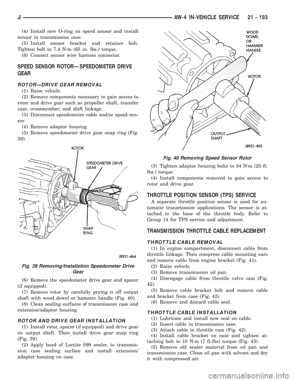
(5) Remove speedometer drive gear snap ring (Fig.
39).
(6) Remove the speedometer drive gear and spacer
(if equipped).
(7) Remove rotor by carefully prying it off output
shaft with wood dowel or hammer handle (Fig. 40).
(8) Clean sealing surfaces of transmission case and
extension/adaptor housing.
ROTOR AND DRIVE GEAR INSTALLATION
(1) Install rotor, spacer (if equipped) and drive gear
on output shaft. Then install drive gear snap ring
(Fig. 39).
(2) Apply bead of Loctite 599 sealer, to transmis-
sion case sealing surface and install extension/
adapter housing on case.(3) Tighten adaptor housing bolts to 34 Nzm (25 ft.
lbs.) torque.
(4) Install components removed to gain access to
rotor and drive gear.
THROTTLE POSITION SENSOR (TPS) SERVICE
A separate throttle position sensor is used for au-
tomatic transmission applications. The sensor is at-
tached to the base of the throttle body. Refer to
Group 14 for TPS service and adjustment.
TRANSMISSION THROTTLE CABLE REPLACEMENT
THROTTLE CABLE REMOVAL
(1) In engine compartment, disconnect cable from
throttle linkage. Then compress cable mounting ears
and remove cable from engine bracket (Fig. 41).
(2) Raise vehicle.
(3) Remove transmission oil pan.
(4) Disengage cable from throttle valve cam (Fig.
42).
(5) Remove cable bracket bolt and remove cable
and bracket from case (Fig. 43).
(6) Remove and discard cable seal.
THROTTLE CABLE INSTALLATION
(1) Lubricate and install new seal on cable.
(2) Insert cable in transmission case.
(3) Attach cable to throttle cam (Fig. 42).
(4) Install cable bracket on case and tighten at-
taching bolt to 10 Nzm (7 ft-lbs) torque (Fig. 43).
(5) Remove old sealer material from oil pan and
transmission case. Clean oil pan with solvent and dry
it with compressed air.
Fig. 40 Removing Speed Sensor Rotor
Fig. 39 Removing/Installation Speedometer Drive
Gear
JAW-4 IN-VEHICLE SERVICE 21 - 193
Page 1764 of 2158
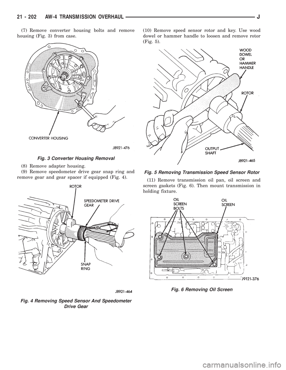
(7) Remove converter housing bolts and remove
housing (Fig. 3) from case.
(8) Remove adapter housing.
(9) Remove speedometer drive gear snap ring and
remove gear and gear spacer if equipped (Fig. 4).(10) Remove speed sensor rotor and key. Use wood
dowel or hammer handle to loosen and remove rotor
(Fig. 5).
(11) Remove transmission oil pan, oil screen and
screen gaskets (Fig. 6). Then mount transmission in
holding fixture.
Fig. 3 Converter Housing Removal
Fig. 4 Removing Speed Sensor And Speedometer
Drive Gear
Fig. 5 Removing Transmission Speed Sensor Rotor
Fig. 6 Removing Oil Screen
21 - 202 AW-4 TRANSMISSION OVERHAULJ
Page 1842 of 2158
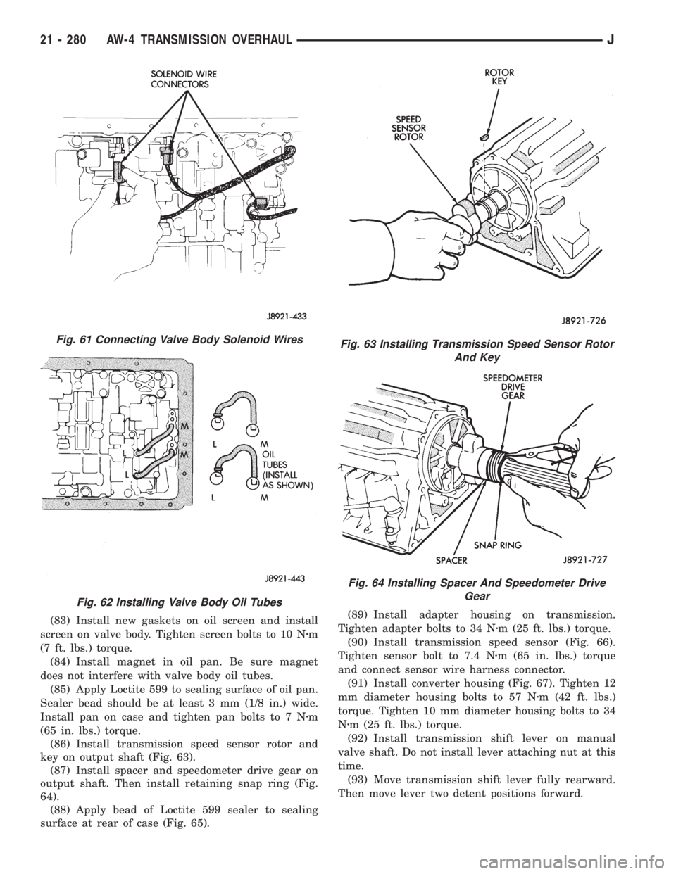
(83) Install new gaskets on oil screen and install
screen on valve body. Tighten screen bolts to 10 Nzm
(7 ft. lbs.) torque.
(84) Install magnet in oil pan. Be sure magnet
does not interfere with valve body oil tubes.
(85) Apply Loctite 599 to sealing surface of oil pan.
Sealer bead should be at least 3 mm (1/8 in.) wide.
Install pan on case and tighten pan bolts to 7 Nzm
(65 in. lbs.) torque.
(86) Install transmission speed sensor rotor and
key on output shaft (Fig. 63).
(87) Install spacer and speedometer drive gear on
output shaft. Then install retaining snap ring (Fig.
64).
(88) Apply bead of Loctite 599 sealer to sealing
surface at rear of case (Fig. 65).(89) Install adapter housing on transmission.
Tighten adapter bolts to 34 Nzm (25 ft. lbs.) torque.
(90) Install transmission speed sensor (Fig. 66).
Tighten sensor bolt to 7.4 Nzm (65 in. lbs.) torque
and connect sensor wire harness connector.
(91) Install converter housing (Fig. 67). Tighten 12
mm diameter housing bolts to 57 Nzm (42 ft. lbs.)
torque. Tighten 10 mm diameter housing bolts to 34
Nzm (25 ft. lbs.) torque.
(92) Install transmission shift lever on manual
valve shaft. Do not install lever attaching nut at this
time.
(93) Move transmission shift lever fully rearward.
Then move lever two detent positions forward.
Fig. 61 Connecting Valve Body Solenoid Wires
Fig. 62 Installing Valve Body Oil Tubes
Fig. 63 Installing Transmission Speed Sensor Rotor
And Key
Fig. 64 Installing Spacer And Speedometer Drive
Gear
21 - 280 AW-4 TRANSMISSION OVERHAULJ
Page 1845 of 2158
NP231 TRANSFER CASE
INDEX
page page
General Information....................... 283
Overhaul Cleaning and Inspection............ 294
Shift Lever Installation (XJ)................. 286
Shift Lever Installation (YJ)................. 286
Shift Lever Removal (XJ)................... 286
Shift Lever Removal (YJ)................... 286
Shift Linkage Adjustment................... 286Speedometer Service..................... 287
Transfer Case Assembly................... 294
Transfer Case Disassembly and Overhaul...... 289
Transfer Case Identification................. 284
Transfer Case Installation.................. 288
Transfer Case Lubricant and Fill Level......... 284
Transfer Case Removal.................... 287
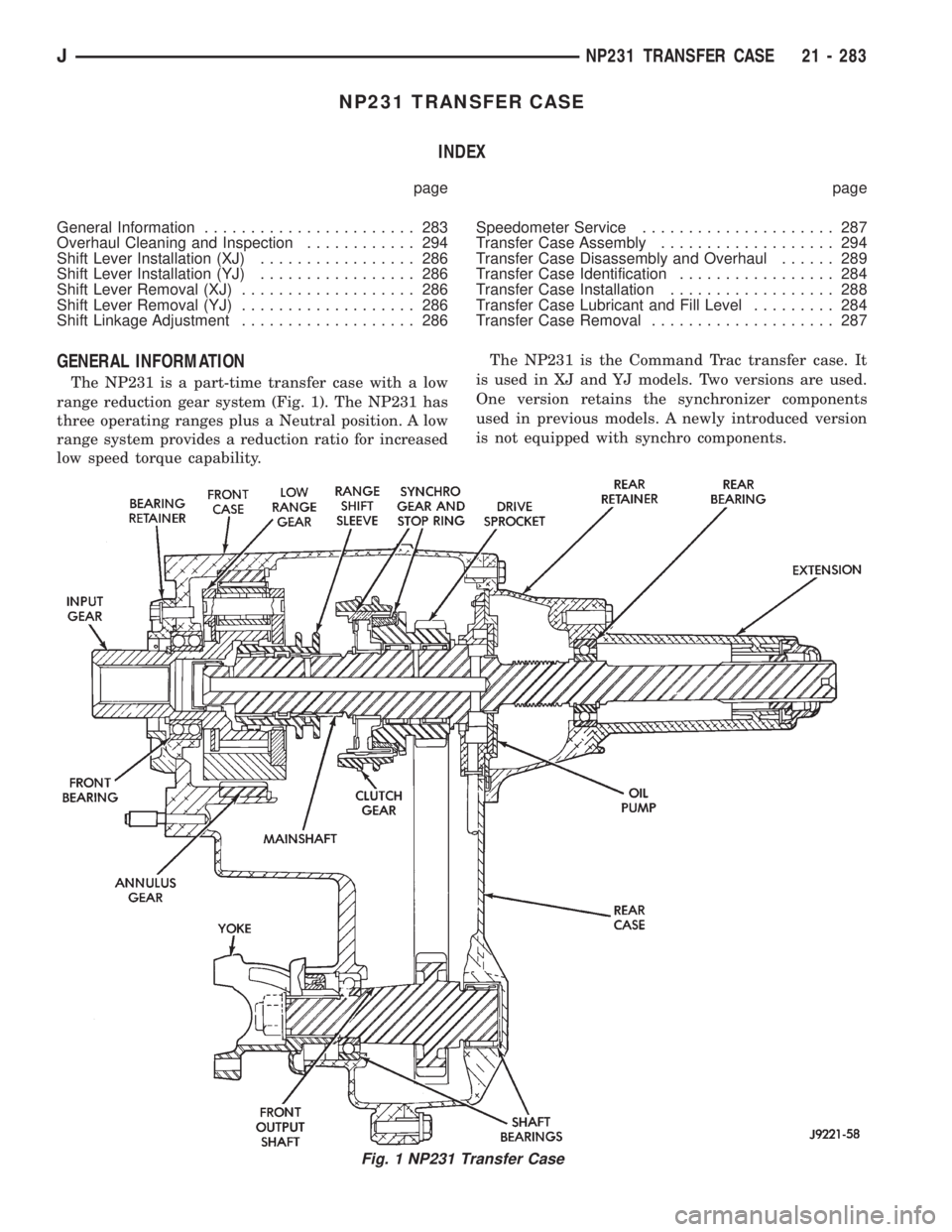
GENERAL INFORMATION
The NP231 is a part-time transfer case with a low
range reduction gear system (Fig. 1). The NP231 has
three operating ranges plus a Neutral position. A low
range system provides a reduction ratio for increased
low speed torque capability.The NP231 is the Command Trac transfer case. It
is used in XJ and YJ models. Two versions are used.
One version retains the synchronizer components
used in previous models. A newly introduced version
is not equipped with synchro components.
Fig. 1 NP231 Transfer Case
JNP231 TRANSFER CASE 21 - 283
Page 1849 of 2158
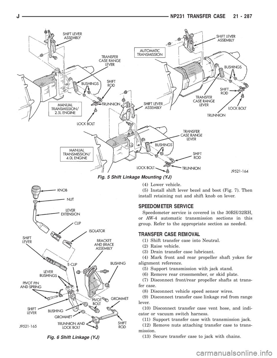
(4) Lower vehicle.
(5) Install shift lever bezel and boot (Fig. 7). Then
install retaining nut and shift knob on lever.
SPEEDOMETER SERVICE
Speedometer service is covered in the 30RH/32RH,
or AW-4 automatic transmission sections in this
group. Refer to the appropriate section as needed.
TRANSFER CASE REMOVAL
(1) Shift transfer case into Neutral.
(2) Raise vehicle.
(3) Drain transfer case lubricant.
(4) Mark front and rear propeller shaft yokes for
alignment reference.
(5) Support transmission with jack stand.
(6) Remove rear crossmember, or skid plate.
(7) Disconnect front/rear propeller shafts at trans-
fer case.
(8) Disconnect vehicle speed sensor wires.
(9) Disconnect transfer case linkage rod from range
lever.
(10) Disconnect transfer case vent hose, and indi-
cator or vacuum switch harness.
(11) Support transfer case with transmission jack.
(12) Remove nuts attaching transfer case to trans-
mission.
(13) Secure transfer case to jack with chains.
Fig. 5 Shift Linkage Mounting (YJ)
Fig. 6 Shift Linkage (YJ)
JNP231 TRANSFER CASE 21 - 287
Page 1866 of 2158
(19) Apply 3 mm (1/8 in.) wide bead of Mopar gas-
ket maker, silicone adhesive sealer, or Loctite 518 to
mounting surface of extension housing.(20) Align and install extension on retainer. Then
install and tighten extension bolts to 27-34 Nzm
(20-25 ft. lbs.) torque.
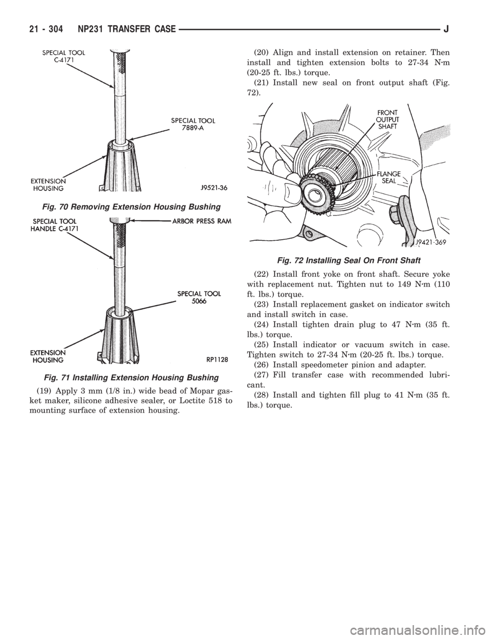
(21) Install new seal on front output shaft (Fig.
72).
(22) Install front yoke on front shaft. Secure yoke
with replacement nut. Tighten nut to 149 Nzm(110
ft. lbs.) torque.
(23) Install replacement gasket on indicator switch
and install switch in case.
(24) Install tighten drain plug to 47 Nzm (35 ft.
lbs.) torque.
(25) Install indicator or vacuum switch in case.
Tighten switch to 27-34 Nzm (20-25 ft. lbs.) torque.
(26) Install speedometer pinion and adapter.
(27) Fill transfer case with recommended lubri-
cant.
(28) Install and tighten fill plug to 41 Nzm (35 ft.
lbs.) torque.
Fig. 70 Removing Extension Housing Bushing
Fig. 71 Installing Extension Housing Bushing
Fig. 72 Installing Seal On Front Shaft
21 - 304 NP231 TRANSFER CASEJ