1995 JEEP YJ speedometer
[x] Cancel search: speedometerPage 625 of 2158

INSTRUMENT CLUSTER
INDEX
page page
ABS Warning Lamp........................ 2
Brake Warning Lamp....................... 2
Charging System Indicator Lamp............... 3
Cluster Ground............................ 3
Diagram Index............................. 3
Engine Coolant Temperature Gauge............ 1
Engine Coolant Temperature Warning Lamp...... 1
Fuel Gauge.............................. 1
High-Beam Indicator Lamp................... 2
Instrument Cluster......................... 1Low Fuel Warning Lamp..................... 1
Low Washer Fluid Warning Lamp.............. 2
Malfunction Indicator Lamp (MIL)............... 2
Manual Transmission Up-Shift Lamp............ 2
Oil Pressure Gauge........................ 2
Oil Pressure Warning Lamp.................. 2
Seat Belt Indicator Warning Lamp.............. 2
Speedometer............................. 2
Tachometer.............................. 2
Turn Signal Indicator Lamps.................. 2
INSTRUMENT CLUSTER
The instrument cluster contains the gauges and
warning lamps. All gauges have magnetic move-
ments.
When the ignition switch is in the START or RUN
position, circuit A21 feeds circuit F87 through fuse 17
in the fuse block. Circuit A1 from fuse 6 in the Power
Distribution Center (PDC) supplies voltage to circuit
A21. Circuit A1 is HOT at all times.
Circuit F87 connects to the cluster connector to
power the gauges and to the telltale connector to
power the warning lamps.
Circuit E2 from fuse 19 in the fuse block feeds the
illumination lamps. Circuit E2 originates at the head-
lamp switch and continues through fuse 19. The
headlamp switch powers circuit E2 when the parking
lamps or headlamp are ON.
Circuit Z2 provides ground for the indicator lamps
and illumination lamps.
ENGINE COOLANT TEMPERATURE GAUGE
Circuit G20 connects the engine coolant tempera-
ture gauge to the engine coolant temperature sensor.
The sensor is a variable resistor and case grounded to
the engine. Circuit F87 connects to the instrument
cluster left connector and supplies voltage for the
gauge.
The gauge uses two coils. Current passing through
the coils creates a magnetic field. Position of the
gauge needle is controlled by the amount of current
passing through the coils to ground at the sensor.
ENGINE COOLANT TEMPERATURE WARNING
LAMP
Circuit G20 connects the engine coolant tempera-
ture warning lamp to the engine coolant temperature
switch. When the switch closes, battery voltage from
circuit F87 flows through the lamp to ground through
the switch on circuit G20. The engine coolant tem-
perature switch is case grounded to the engine. Cir-cuit F87 connects to the instrument cluster connector
and supplies voltage for the lamp.
Circuit G20 also connects to the warning lamp to
ground when the ignition switch is in the START
position. When the ignition switch is in the START
position, the lamp illuminates for a bulb test.
FUEL GAUGE
The fuel level sensor is a variable resistor. Circuit
G4 connects the fuel level sensor to the fuel gauge in
the instrument cluster. Circuit F87 from fuse 17 in
the fuse block supplies voltage to the fuel gauge. The
fuel level sensor draws voltage from circuit F87
through the fuel gauge on circuit G4. Circuit G4
connects to circuit 57 in the fuel pump module har-
ness. Circuit 57 connects to the fuel level sensor.
Circuit 99 in the fuel pump module harness con-
nects to circuit Z1. Circuit Z1 provides the ground
path for the fuel level sensor. The grounding point for
circuit Z1 is the left side of the cowl panel.
As current flows through the coils in the fuel gauge,
it creates a magnetic field. One of the coils in the
gauge receives fixed current. The other coil is con-
nected to the level sensor. The magnetic field controls
the position of the fuel gauge pointer.
The fuel level sensor contains a variable resistor. As
the position of the float arm on the fuel level sensor
changes, the resistor changes the current flow
through second coil in the fuel gauge. A change in
current flow alters the magnetic field in the fuel
gauge, which changes the pointer position.
LOW FUEL WARNING LAMP
Circuit G4 connects the fuel level sensor to the fuel
gauge. The low fuel level module at the rear of the
gauge monitors resistance in circuit G4. The low fuel
level module powers an light emitting diode (LED)
when the resistance in circuit G4 reaches a calibrated
level. The LED illuminates the Low Fuel indicator.
Refer to Group 8E for additional information.
J8W-40 INSTRUMENT CLUSTERÐXJ VEHICLES 8W - 40 - 1
Page 626 of 2158

OIL PRESSURE GAUGE
The case grounded oil pressure sensor is a variable
resistor that connects to circuit G6. Circuit G6 con-
nects to the oil pressure gauge.
Circuit F87 connects to the instrument cluster con-
nector and supplies battery voltage to oil pressure
gauge. The gauge uses two coils. Current passing
through the coils creates a magnetic field. Position of
the gauge needle is controlled by the amount of cur-
rent passing through the coils to ground at the sen-
sor.
OIL PRESSURE WARNING LAMP
The case grounded oil pressure switch connects to
circuit G6. Circuit G6 connects to the oil pressure
warning lamp. Circuit F87 connects to the instru-
ment cluster connector and supplies battery voltage
to oil pressure lamp.
When the oil pressure switch close, battery voltage
flows through the warning lamp to ground through
the switch, illuminating the lamp.
TACHOMETER
The tachometer module in the instrument cluster
operates the tachometer. The Powertrain Control
Module (PCM) supplies the signal for the tachometer
on circuit G21. Circuit G21 connects to cavity 43 of
the PCM.
SPEEDOMETER
The speedometer and odometer receive a signal
from the vehicle speed sensor on circuit G7. Circuit
G7 also connects to the Powertrain Control Module
(PCM) at cavity 47.
ABS WARNING LAMP
Circuit F87 provides power for the ABS warning
lamp at the instrument cluster. Ground for the ABS
warning lamp is provided by either the ABS control
module or by the ABS power relay when the relay is
not energized. The ABS control module illuminates
the lamp by providing ground on circuit B205.
Circuit B205 splices to connect to circuit B235
through a diode. When the ABS power relay is not
energized, it connects circuit B235 to circuit Z12. The
ground path for the warning lamp is through the di-
ode to circuit B235, through the ABS power relay to
ground on circuit Z12.
The diode between circuit B205 and B235 prevents
voltage from flowing to the ABS control module when
the ABS power relay switches to supply power on cir-
cuit B235.
MALFUNCTION INDICATOR LAMP (MIL)
The PCM provides ground for the instrument clus-
ter malfunction indicator lamp on circuit G3. Circuit
G3 connects to cavity 32 of the PCM. Circuit F87provides voltage for the lamp. The MIL displays the
message CHECK ENGINE when illuminated.
For information regarding diagnostic trouble code
access using the MIL lamp, refer to Group 14, Fuel
Systems.
LOW WASHER FLUID WARNING LAMP
Circuit G29 connects the low washer fluid switch to
the warning lamp in the instrument cluster. Circuit
F12 supplies battery voltage to the switch.
When the low washer fluid switch closes, it con-
nects circuits G29 and F12. Battery voltage from cir-
cuit F12 powers the low washer fluid lamp. Circuit
Z1 at the instrument cluster provides ground to illu-
minate the warning lamp.
SEAT BELT INDICATOR WARNING LAMP
The seat belt indicator warning lamp is activated
by the chime/buzzer on circuit G11. Circuit G11 sup-
plies power to instrument cluster for the lamp. Cir-
cuit Z1 provides ground for the lamp at the cluster.
The chime/buzzer module powers circuit G11 after
it receives an input on circuit G10 indicating the seat
belt switch is open.
HIGH-BEAM INDICATOR LAMP
Circuit L3 supplies power for the high-beam indi-
cator lamp. The ground path for the lamp is through
circuit Z1. If the vehicle has Daytime Running
Lamps (DRL), the DRL module powers circuit L3
through circuit G465. On vehicles not equipped with
DRL, the headlamp switch powers circuit L3.
Circuit Z1 provides ground for the indicator lamp
at the cluster.
TURN SIGNAL INDICATOR LAMPS
Circuits L61 and L60 power for the turn signal in-
dicator lamps. Circuit L61 powers the left indicator
lamp. Circuit L60 powers the right indicator lamp.
Circuit Z1 provides ground for the lamps.
BRAKE WARNING LAMP
Circuit F87 supplies power to the park brake lamp.
Ground for the park brake lamp is supplied through
the case grounded park brake switch or brake warn-
ing switch on circuit G9. Circuit G9 Connects to cir-
cuit B203. Circuit B203 connects to the brake
warning lamp at the instrument cluster.
MANUAL TRANSMISSION UP-SHIFT LAMP
Circuit F87 supplies power for the manual trans-
mission up-shift lamp. The lamp illuminates when
the Powertrain Control Module (PCM) provides
ground for the lamp on circuit K54. Circuit K54 con-
nects to cavity 54 of the PCM.
8W - 40 - 2 8W-40 INSTRUMENT CLUSTERÐXJ VEHICLESJ
Page 863 of 2158

HELPFUL INFORMATION
²Circuit G7 splices to the speedometer.
²Circuit K7 splices to supply 8 volts to the camshaft
position sensor and crankshaft position sensor.
Circuit K4 splices to supply ground for the signals
from the following:
²Heated oxygen sensor
²Camshaft position sensor
²Crankshaft position sensor
²Throttle position sensor
²Manifold absolute pressure sensor
²Engine coolant temperature sensor
²Intake air temperature sensor
HEATED OXYGEN SENSOR
When the fuel pump relay contacts close, they con-
nect circuits A14 and A141. Circuit A141 splices to
supply voltage to the heated oxygen sensor.
Circuit K41 delivers the signal from the heated ox-
ygen sensor to the PCM. Circuit K41 connects to cav-
ity 41 of the PCM.
The PCM provides a ground for the heated oxygen
sensor signal (circuit K41) through circuit K4. Circuit
K4 connects to cavity 4 of the PCM connector.
Circuit Z12 provides a ground for the heater circuit
in the sensor.
HELPFUL INFORMATION
²Circuit A141 also supplies battery voltage to the
fuel pump.
Circuit K4 splices to supply ground for the signals
from the following:
²Camshaft position sensor
²Crankshaft position sensor
²Intake air temperature sensor
²Throttle position sensor
²Manifold absolute pressure sensor
²Engine coolant temperature sensor
²Vehicle speed sensor
CAMSHAFT POSITION SENSOR
The Powertrain Control Module (PCM) supplies 8
volts to the camshaft position sensor (in distributor)
on circuit K7. Circuit K7 connects to cavity 7 of the
PCM.
The PCM receives the camshaft position sensor sig-
nal on circuit K44. Circuit K44 connects to cavity 44
of the PCM.
The PCM provides a ground for the camshaft posi-
tion sensor signal (circuit K44) through circuit K4.
Circuit K4 connects to cavity 4 of the PCM.
HELPFUL INFORMATION
²Circuit K7 splices to supply 8 volts to the crank-
shaft position sensor and the vehicle speed sensor.
Circuit K4 splices to supply ground for the signals
from the following:
²Heated oxygen sensor²Crankshaft position sensor
²Intake air temperature sensor
²Throttle position sensor
²Manifold absolute pressure sensor
²Engine coolant temperature sensor
²Vehicle speed sensor
CRANKSHAFT POSITION SENSOR
The Powertrain Control Module (PCM) supplies 8
volts to the crankshaft position sensor on circuit K7.
Circuit K7 connects to cavity 7 of the PCM.
The PCM receives the crankshaft position sensor
signal on circuit K24. Circuit K24 connects to cavity
24 of the PCM.
The PCM provides a ground for the crankshaft po-
sition sensor (circuit K24) through circuit K4. Circuit
K4 connects to cavity 4 of the PCM.
HELPFUL INFORMATION
²Circuit K7 splices to supply 8 volts to the camshaft
position sensor and the vehicle speed sensor.
Circuit K4 splices to supply ground for the signals
from the following:
²Heated oxygen sensor
²Camshaft position sensor
²Intake air temperature sensor
²Throttle position sensor
²Manifold absolute pressure sensor
²Engine coolant temperature sensor
²Vehicle speed sensor
ENGINE COOLANT TEMPERATURE SENSOR
The engine coolant temperature sensor provides an
input to the
Powertrain Control Module (PCM) on circuit K2.
From circuit K2, the engine coolant temperature sen-
sor draws up to 5 volts from the PCM. The sensor is
a variable resistor. As coolant temperature changes,
the resistance in the sensor changes, causing a
change in current draw. The K2 circuit connects to
cavity 2 of the PCM.
The PCM provides a ground for the engine coolant
temperature sensor signal (circuit K2) through circuit
K4. Circuit K4 connects to cavity 4 of the PCM con-
nector.
HELPFUL INFORMATION
Circuit K4 splices to supply ground for the signals
from the following:
²Heated oxygen sensor
²Camshaft position sensor
²Crankshaft position sensor
²Intake air temperature sensor
²Throttle position sensor
²Manifold absolute pressure sensor
²Vehicle speed sensor
J8W-30 FUEL/IGNITIONÐXJ-RHD 8W - 30 - 3
Page 1124 of 2158
²Circuit K60 connects to cavity 60 of the PCM.
VEHICLE SPEED SENSOR
Circuit K7 supplies 8 volts from the Powertrain
Control Module (PCM) to the vehicle speed sensor.
The K7 circuit connects to cavity 7 of the PCM.
Circuit G7 from the vehicle speed sensor provides
an input signal to the PCM. The G7 circuit connects
to cavity 47 of the PCM.
The PCM provides a ground for the vehicle speed
sensor signal (circuit G7) through circuit K4. Circuit
K4 connects to cavity 4 of the PCM.
HELPFUL INFORMATION
²Circuit G7 splices to the speedometer, and Day-
time Running Lamp module (DRL).
²Circuit K7 splices to supply 8 volts to the camshaft
position sensor and crankshaft position sensor.
Circuit K4 splices to supply ground for the signals
from the following:
²Heated oxygen sensor
²Camshaft position sensor
²Crankshaft position sensor
²Throttle position sensor
²Manifold absolute pressure sensor
²Engine coolant temperature sensor
²Intake air temperature sensor
HEATED OXYGEN SENSOR
When the Automatic Shut Down (ASD) relay con-
tacts close, they connect circuits A14 and A142. Cir-
cuit A142 splices to supply voltage to the heated
oxygen sensor.
Circuit K41 delivers the signal from the heated ox-
ygen sensor to the Powertrain Control Module
(PCM). Circuit K41 connects to cavity 41 of the PCM.
The PCM provides a ground for the heated oxygen
sensor signal (circuit K41) through circuit K4. Circuit
K4 connects to cavity 4 of the PCM connector.
Circuit Z1 provides a ground for the heater circuit
in the sensor. Circuit Z1 terminates at the rear of the
engine.
HELPFUL INFORMATION
²Along with supplying voltage to the ASD relay
contacts, circuit A14 supplies voltage to the contact
side of the fuel pump relay.
²Circuit A142 splices to supply voltage to the fuel
injectors, ignition coil, and heated oxygen sensor.
Circuit K4 splices to supply ground for the signals
from the following:
²Camshaft position sensor
²Crankshaft position sensor
²Intake air temperature sensor
²Throttle position sensor
²Manifold absolute pressure sensor
²Engine coolant temperature sensor
²Vehicle speed sensor
CAMSHAFT POSITION SENSOR
The Powertrain Control Module (PCM) supplies 8
volts to the camshaft position sensor (in distributor)
on circuit K7. Circuit K7 connects to cavity 7 of the
PCM.
The PCM receives the camshaft position sensor sig-
nal on circuit K44. Circuit K44 connects to cavity 44
of the PCM.
The PCM provides a ground for the camshaft posi-
tion sensor signal (circuit K44) through circuit K4.
Circuit K4 connects to cavity 4 of the PCM.
HELPFUL INFORMATION
²Circuit K7 splices to supply 8 volts to the crank-
shaft position sensor and the vehicle speed sensor.
Circuit K4 splices to supply ground for the signals
from the following:
²Heated oxygen sensor
²Crankshaft position sensor
²Intake air temperature sensor
²Throttle position sensor
²Manifold absolute pressure sensor
²Engine coolant temperature sensor
²Vehicle speed sensor
CRANKSHAFT POSITION SENSOR
The Powertrain Control Module (PCM) supplies 8
volts to the crankshaft position sensor on circuit K7.
Circuit K7 connects to cavity 7 of the PCM.
The PCM receives the crankshaft position sensor
signal on circuit K24. Circuit K24 connects to cavity
24 of the PCM.
The PCM provides a ground for the crankshaft po-
sition sensor (circuit K24) through circuit K4. Circuit
K4 connects to cavity 4 of the PCM.
HELPFUL INFORMATION
²Circuit K7 splices to supply 8 volts to the crank-
shaft position sensor and the vehicle speed sensor.
Circuit K4 splices to supply ground for the signals
from the following:
²Heated oxygen sensor
²Camshaft position sensor
²Intake air temperature sensor
²Throttle position sensor
²Manifold absolute pressure sensor
²Engine coolant temperature sensor
²Vehicle speed sensor
ENGINE COOLANT TEMPERATURE SENSOR
The engine coolant temperature sensor provides an
input to the Powertrain Control Module (PCM) on
circuit K2. From circuit K2, the engine coolant tem-
perature sensor draws up to 5 volts from the PCM.
The sensor is a variable resistor. As coolant temper-
ature changes, the resistance in the sensor changes,
causing a change in current draw. The K2 circuit
connects to cavity 2 of the PCM.
J8W-30 FUEL/IGNITIONÐYJ VEHICLES 8W - 30 - 3
Page 1154 of 2158
INSTRUMENT CLUSTER
INSTRUMENT CLUSTER
The instrument cluster contains the gauges and
warning lamps. All gauges have magnetic move-
ments.
When the ignition switch is in either the START or
RUN position, circuit A1 from fuse 4 in the Power
Distribution Center (PDC) connects to circuit A21.
Circuit A21 powers fuse 9 in the fuse block. Fuse 9
powers circuit G5. One branch of circuit G5 connects
directly to the combination buzzer. The other branch
of circuit G5 splices to power the gauges, speedome-
ter, tachometer, voltmeter, indicator lamps, and
warning lamps in the instrument cluster.
When the parking lamps or headlamps are ON, the
headlamp switch connects circuit F33 to circuit L7.
Circuit L7 splices to the dimmer switch. Circuit E1
from the dimmer switch powers fuse 10 in the fuse
block when the parking lamps or headlamps are ON.
Circuit E2 from fuse 10 in the fuse block feeds the
illumination lamps in the instrument cluster.
Circuit Z1 provides ground the instrument cluster
illumination lamps, gauges and warning lamps.
HELPFUL INFORMATION
²Circuit G5 also powers the heated rear window,
A/C compressor clutch relay. On Canadian vehicles,
circuit G5 powers the Daytime Running Lamps
(DRL) module.
²Circuit F33 originates at fuse 8 in the fuse block.
Circuit A6 from fuse 3 in the PDC powers fuse 8 in
the fuse block.
ENGINE COOLANT TEMPERATURE GAUGE
Circuit G20 connects the engine coolant tempera-
ture gauge to the engine coolant temperature sensor.
The sensor is a variable resistor and case grounded
to the engine. Circuit G5 connects to the instrument
cluster and supplies voltage for the gauge.
The gauge uses two coils. The first coil has fixed
current flowing through it to maintain magnetic field
strength. Circuit Z1 provides ground for the fixed
current coil. The current level passing through the
second coil is controlled by the variable resistor in
the engine coolant temperature sender. The changing
current varies the magnetic field in the second coil.
Refer to group 8E, Instrument Panel and Gauges
for gauge operation.
FUEL GAUGE
Circuit G4 connects the fuel level sensor to the fuel
gauge in the instrument cluster. Circuit G5 supplies
voltage to the fuel gauge. The fuel level sensor draws
voltage from circuit G5 through the fuel gauge on cir-
cuit G4.The gauge uses two coils. The first coil has fixed
current flowing through it to maintain magnetic field
strength. Circuit Z1 provides ground for the fixed
current coil. The current level passing through the
second coil is controlled by the variable resistor in
the fuel level sensor. The changing current varies the
magnetic field in the second coil.
Circuit Z2 provides the ground path for the fuel
level sensor.
Refer to group 8E, Instrument Panel and Gauges
for gauge operation.
OIL PRESSURE GAUGE
The case grounded oil pressure sending unit is a
variable resistor. The sending unit connects to the oil
pressure gauge on circuit G60.
Circuit G5 connects to the instrument cluster and
supplies battery voltage to the oil pressure gauge.
The gauge uses two coils. The first coil has fixed cur-
rent flowing through it to maintain magnetic field
strength. Circuit Z1 provides ground for the fixed
current coil. The current level passing through the
second coil is controlled by the variable resistor in
the oil pressure sending unit. The changing current
varies the magnetic field in the second coil.
Refer to group 8E, Instrument Panel and Gauges
for gauge operation.
TACHOMETER
The Powertrain Control Module (PCM) provides
the tachometer signal to the electronic tachometer on
circuit G21. Circuit G21 originates at cavity 43 of the
PCM. Circuit Z1 provides ground for the tachometer's
internal logic circuits.
SPEEDOMETER
The electronic speedometer and odometer receive a
signal from the vehicle speed sensor on circuit G7.
Circuit G5 connects to the instrument cluster and
supplies battery voltage to the speedometer. Circuit
Z1 provides ground for the speedometer internal logic
circuits.
Circuit G7 splices to connect to the Powertrain
Control Module (PCM) and if equipped, the Daytime
Running Lamps (DRL) module.
FOUR-WHEEL DRIVE (4WD) INDICATOR LAMP
When the 4WD switch closes, circuit Z1 provides
ground for the 4WD indicator lamp in the instrument
panel. Circuit G5 connects to the instrument cluster
and supplies battery voltage to the 4WD indicator
lamp. Circuit G1 connects the indicator lamp to the
4WD switch.
J8W-40 INSTRUMENT CLUSTERÐYJ VEHICLES 8W - 40 - 1
Page 1469 of 2158
speedometer pinion gear adapter (Fig. 29). Do not re-
move the gear adapter from the transmission.
INSTALLATION
(1) Clean the inside of speedometer pinion gear
adapter before installing speed sensor.
(2) Install sensor into speedometer gear adapter
and install mounting bolt.Before tightening bolt,verify speed sensor is fully seated (mounted
flush) to speedometer pinion gear adapter.
(3) Tighten sensor mounting bolt to 2.2 Nzm (20 in.
lbs.) torque.
(4) Connect electrical connector to sensor.
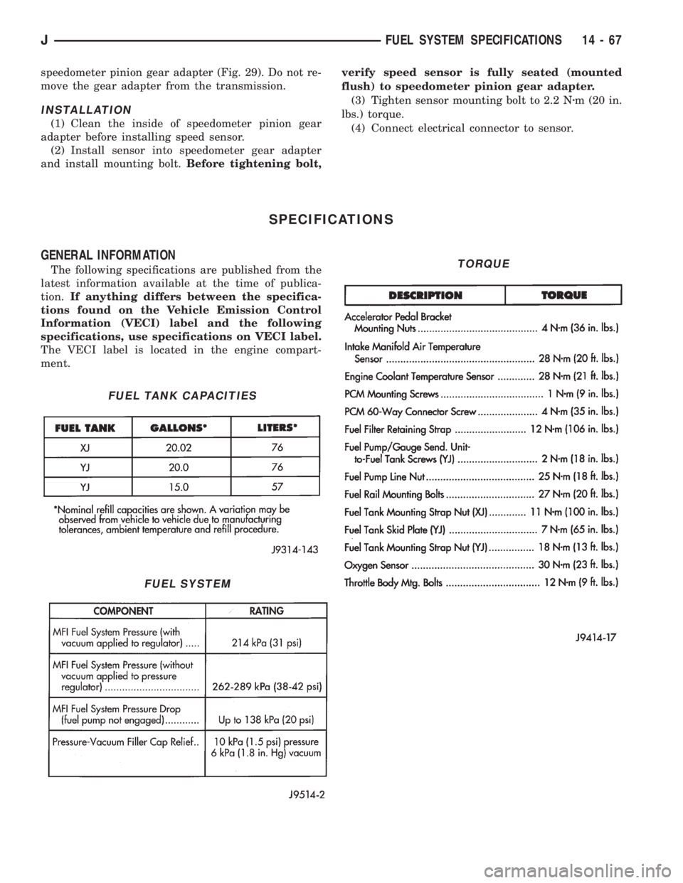
SPECIFICATIONS
GENERAL INFORMATION
The following specifications are published from the
latest information available at the time of publica-
tion.If anything differs between the specifica-
tions found on the Vehicle Emission Control
Information (VECI) label and the following
specifications, use specifications on VECI label.
The VECI label is located in the engine compart-
ment.
FUEL TANK CAPACITIES
FUEL SYSTEM
TORQUE
JFUEL SYSTEM SPECIFICATIONS 14 - 67
Page 1567 of 2158
(21) Remove clutch release bearing, release fork
and retainer clip.
(22) Remove clutch housing from transmission.
TRANSMISSION INSTALLATION
(1) Install clutch housing on transmission. Tighten
housing bolts to 37 Nzm (27 ft. lbs.) torque.
(2) Lubricate contact surfaces of release fork pivot
ball stud and release fork with high temp grease.
Then install release bearing, fork and retainer clip.
(3) Mount transmission on transmission jack.
(4) Lightly lubricate pilot bearing and transmis-
sion input shaft splines with Mopar high temp
grease.
(5) Align transmission input shaft, release bearing,
and clutch disc splines. Then slide transmission into
place.
(6) Install and tighten clutch housing-to-engine
bolts to 38 Nzm (28 ft. lbs.) torque.Be sure the
housing is properly seated on engine block be-
fore tightening bolts.
(7) Lower transmission approximately 7-8 cm (3
in.) for access to shift tower. Be sure transmission is
in first or third gear.
(8) Reach up and around transmission and insert
shift lever in shift tower. Press lever retainer down-
ward and turn it clockwise to lock it in place. Then
install lever dust boot on shift tower.
(9) Install slave cylinder in clutch housing.
(10) Align and install transfer case on and trans-
mission. Tighten transfer case-to-transmission nuts
to 35 Nzm (26 ft. lbs.) torque.
(11) Connect transfer case vent hose and shift link-
age. Check and adjust linkage if necessary.
(12) Connect transfer case vent hose.
(13) Secure wire harnesses in clips/tie straps on
transmission and transfer case.
(14) Connect backup light switch wires.
(15) Connect vehicle speed sensor wires.
(16) Install and connect crankshaft position sensor.
(17) Install rear crossmember (Fig. 5). On XJ,
tighten crossmember-to-frame bolts to 41 Nzm (31 ft.
lbs.) torque. Then tighten transmission-to-rear sup-
port bolts/nuts to 45 Nzm (33 ft. lbs.) torque. On YJ,
tighten bolts/nuts to indicated torque (Fig. 5).
(18) Remove jack stand.
(19) Align and install front/rear propeller shafts.
Tighten shaft U-joint clamp bolts to 19 Nzm (170 in.
lbs.) torque.
(20) Install skid plate, if equipped. Tighten bolts to
42 Nzm (31 ft. lbs.) torque. Tighten stud nuts to 17
Nzm (150 in. lbs.) torque.
(21) Top off transmission and transfer case lubri-
cant levels.
(22) Lower vehicle.
TRANSMISSION DISASSEMBLY AND OVERHAUL
ADAPTER HOUSING AND FRONT BEARING
RETAINER REMOVAL
(1) Drain transmission lubricant.
(2) Remove release bearing and lever.
(3) Remove clutch housing bolts and remove hous-
ing.
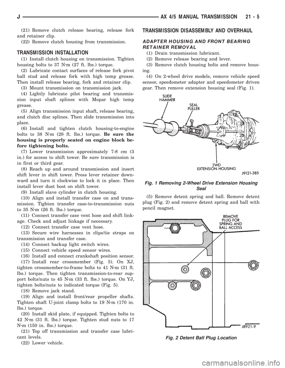
(4) On 2-wheel drive models, remove vehicle speed
sensor, speedometer adapter and speedometer driven
gear. Then remove extension housing seal (Fig. 1).
(5) Remove detent spring and ball. Remove detent
plug (Fig. 2) and remove detent spring and ball with
pencil magnet.
Fig. 1 Removing 2-Wheel Drive Extension Housing
Seal
Fig. 2 Detent Ball Plug Location
JAX 4/5 MANUAL TRANSMISSION 21 - 5
Page 1603 of 2158
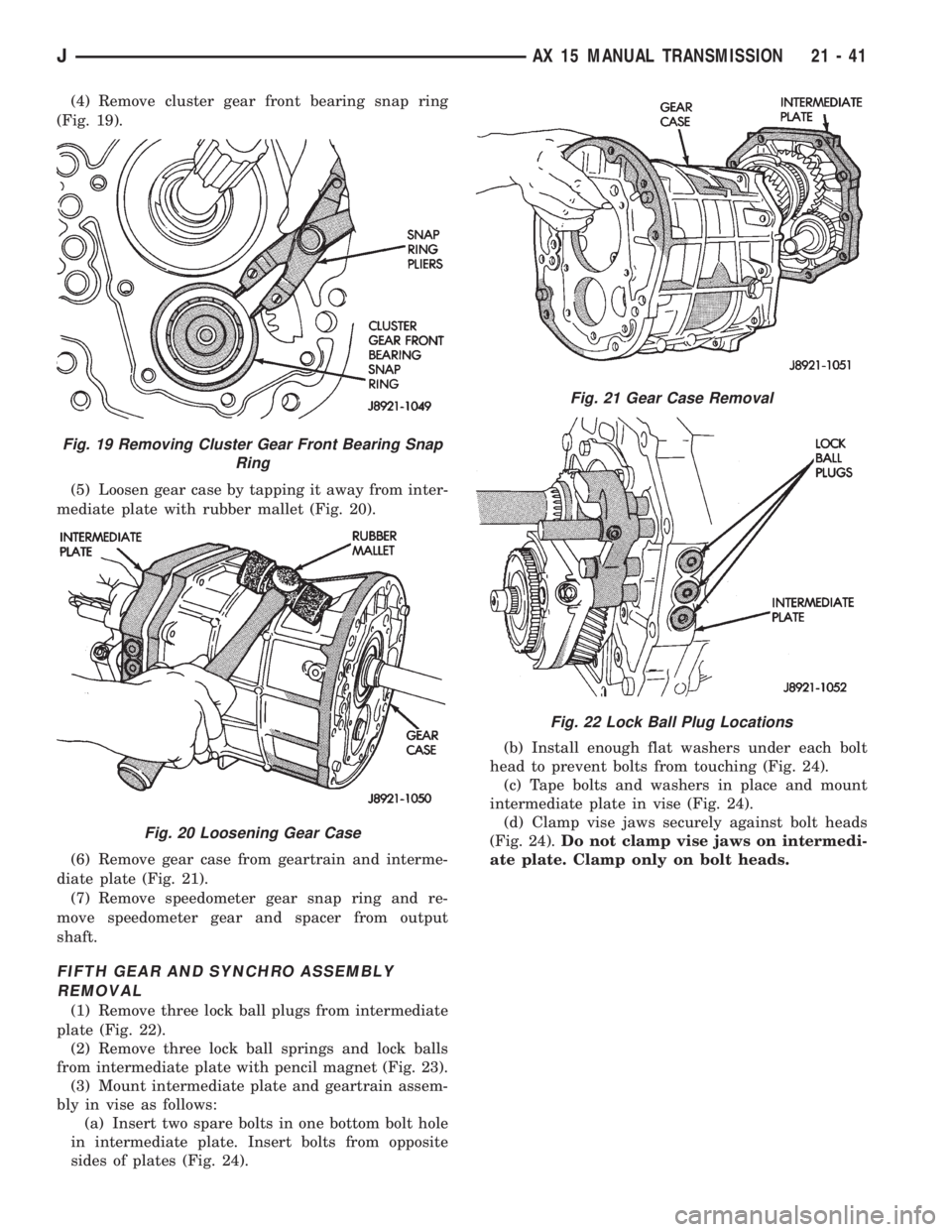
(4) Remove cluster gear front bearing snap ring
(Fig. 19).
(5) Loosen gear case by tapping it away from inter-
mediate plate with rubber mallet (Fig. 20).
(6) Remove gear case from geartrain and interme-
diate plate (Fig. 21).
(7) Remove speedometer gear snap ring and re-
move speedometer gear and spacer from output
shaft.
FIFTH GEAR AND SYNCHRO ASSEMBLY
REMOVAL
(1) Remove three lock ball plugs from intermediate
plate (Fig. 22).
(2) Remove three lock ball springs and lock balls
from intermediate plate with pencil magnet (Fig. 23).
(3) Mount intermediate plate and geartrain assem-
bly in vise as follows:
(a) Insert two spare bolts in one bottom bolt hole
in intermediate plate. Insert bolts from opposite
sides of plates (Fig. 24).(b) Install enough flat washers under each bolt
head to prevent bolts from touching (Fig. 24).
(c) Tape bolts and washers in place and mount
intermediate plate in vise (Fig. 24).
(d) Clamp vise jaws securely against bolt heads
(Fig. 24).Do not clamp vise jaws on intermedi-
ate plate. Clamp only on bolt heads.
Fig. 19 Removing Cluster Gear Front Bearing Snap
Ring
Fig. 20 Loosening Gear Case
Fig. 21 Gear Case Removal
Fig. 22 Lock Ball Plug Locations
JAX 15 MANUAL TRANSMISSION 21 - 41