1995 JEEP YJ brakes
[x] Cancel search: brakesPage 178 of 2158
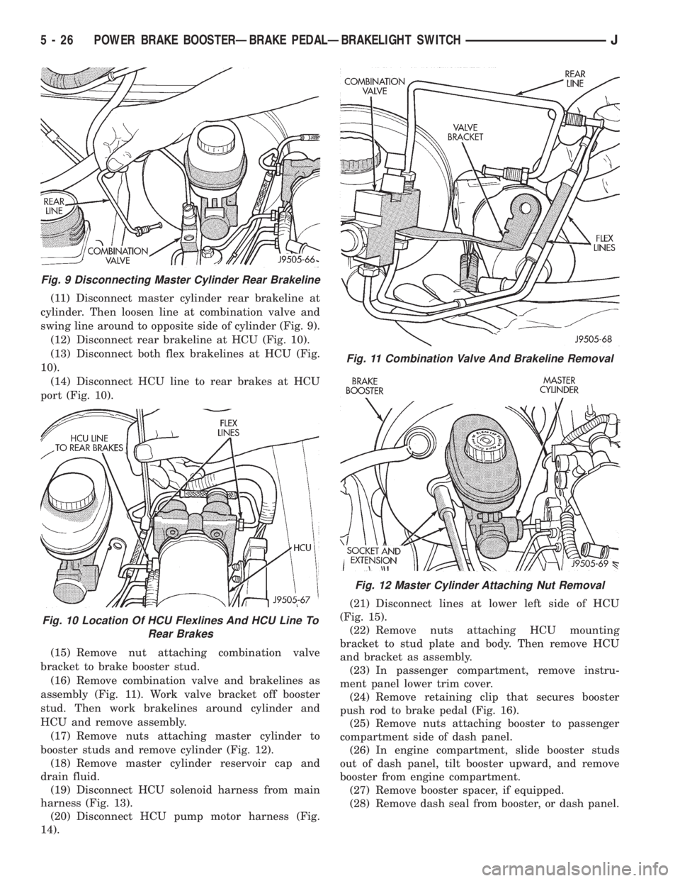
(11) Disconnect master cylinder rear brakeline at
cylinder. Then loosen line at combination valve and
swing line around to opposite side of cylinder (Fig. 9).
(12) Disconnect rear brakeline at HCU (Fig. 10).
(13) Disconnect both flex brakelines at HCU (Fig.
10).
(14) Disconnect HCU line to rear brakes at HCU
port (Fig. 10).
(15) Remove nut attaching combination valve
bracket to brake booster stud.
(16) Remove combination valve and brakelines as
assembly (Fig. 11). Work valve bracket off booster
stud. Then work brakelines around cylinder and
HCU and remove assembly.
(17) Remove nuts attaching master cylinder to
booster studs and remove cylinder (Fig. 12).
(18) Remove master cylinder reservoir cap and
drain fluid.
(19) Disconnect HCU solenoid harness from main
harness (Fig. 13).
(20) Disconnect HCU pump motor harness (Fig.
14).(21) Disconnect lines at lower left side of HCU
(Fig. 15).
(22) Remove nuts attaching HCU mounting
bracket to stud plate and body. Then remove HCU
and bracket as assembly.
(23) In passenger compartment, remove instru-
ment panel lower trim cover.
(24) Remove retaining clip that secures booster
push rod to brake pedal (Fig. 16).
(25) Remove nuts attaching booster to passenger
compartment side of dash panel.
(26) In engine compartment, slide booster studs
out of dash panel, tilt booster upward, and remove
booster from engine compartment.
(27) Remove booster spacer, if equipped.
(28) Remove dash seal from booster, or dash panel.
Fig. 9 Disconnecting Master Cylinder Rear Brakeline
Fig. 10 Location Of HCU Flexlines And HCU Line To
Rear Brakes
Fig. 11 Combination Valve And Brakeline Removal
Fig. 12 Master Cylinder Attaching Nut Removal
5 - 26 POWER BRAKE BOOSTERÐBRAKE PEDALÐBRAKELIGHT SWITCHJ
Page 181 of 2158
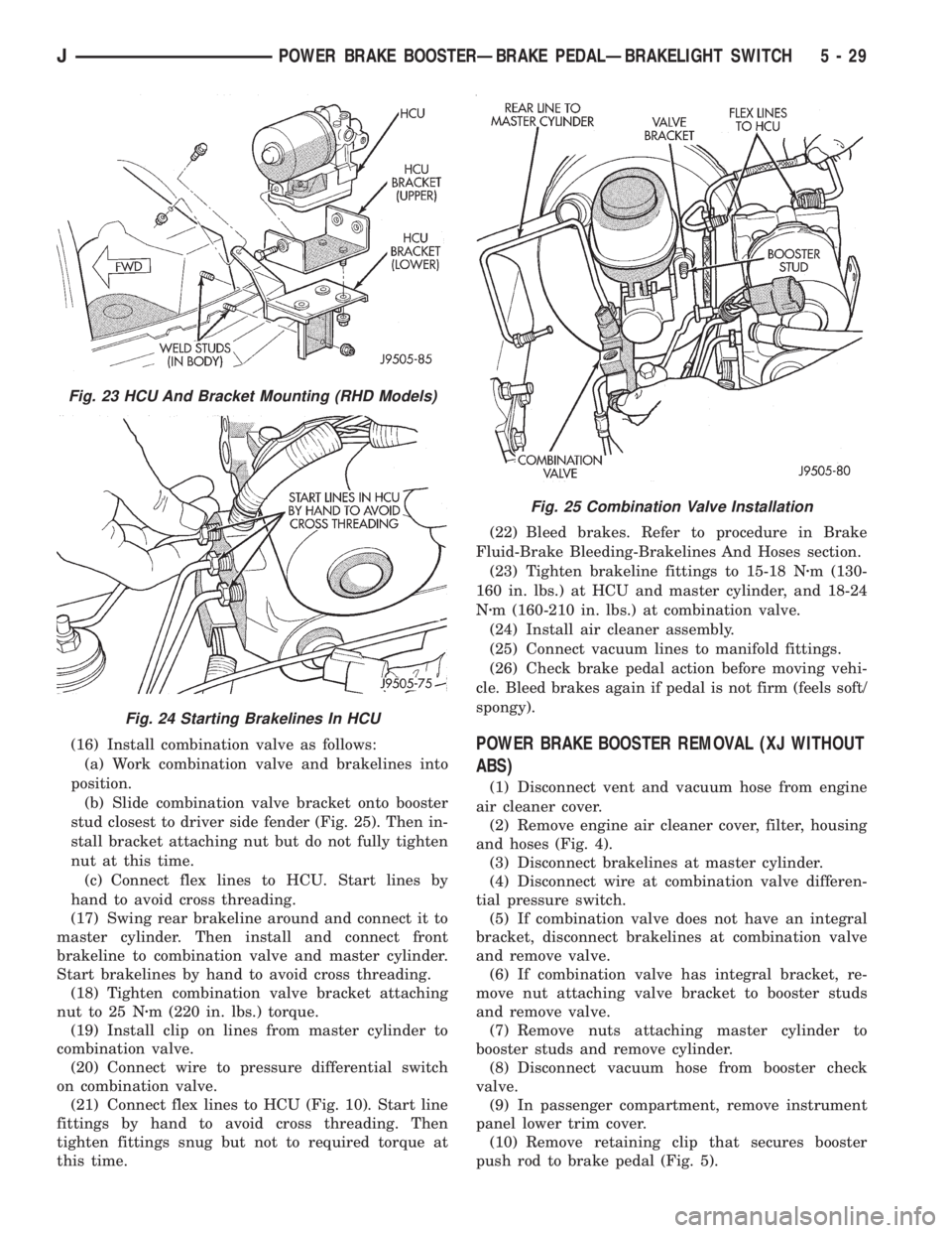
(16) Install combination valve as follows:
(a) Work combination valve and brakelines into
position.
(b) Slide combination valve bracket onto booster
stud closest to driver side fender (Fig. 25). Then in-
stall bracket attaching nut but do not fully tighten
nut at this time.
(c) Connect flex lines to HCU. Start lines by
hand to avoid cross threading.
(17) Swing rear brakeline around and connect it to
master cylinder. Then install and connect front
brakeline to combination valve and master cylinder.
Start brakelines by hand to avoid cross threading.
(18) Tighten combination valve bracket attaching
nut to 25 Nzm (220 in. lbs.) torque.
(19) Install clip on lines from master cylinder to
combination valve.
(20) Connect wire to pressure differential switch
on combination valve.
(21) Connect flex lines to HCU (Fig. 10). Start line
fittings by hand to avoid cross threading. Then
tighten fittings snug but not to required torque at
this time.(22) Bleed brakes. Refer to procedure in Brake
Fluid-Brake Bleeding-Brakelines And Hoses section.
(23) Tighten brakeline fittings to 15-18 Nzm (130-
160 in. lbs.) at HCU and master cylinder, and 18-24
Nzm (160-210 in. lbs.) at combination valve.
(24) Install air cleaner assembly.
(25) Connect vacuum lines to manifold fittings.
(26) Check brake pedal action before moving vehi-
cle. Bleed brakes again if pedal is not firm (feels soft/
spongy).POWER BRAKE BOOSTER REMOVAL (XJ WITHOUT
ABS)
(1) Disconnect vent and vacuum hose from engine
air cleaner cover.
(2) Remove engine air cleaner cover, filter, housing
and hoses (Fig. 4).
(3) Disconnect brakelines at master cylinder.
(4) Disconnect wire at combination valve differen-
tial pressure switch.
(5) If combination valve does not have an integral
bracket, disconnect brakelines at combination valve
and remove valve.
(6) If combination valve has integral bracket, re-
move nut attaching valve bracket to booster studs
and remove valve.
(7) Remove nuts attaching master cylinder to
booster studs and remove cylinder.
(8) Disconnect vacuum hose from booster check
valve.
(9) In passenger compartment, remove instrument
panel lower trim cover.
(10) Remove retaining clip that secures booster
push rod to brake pedal (Fig. 5).
Fig. 23 HCU And Bracket Mounting (RHD Models)
Fig. 24 Starting Brakelines In HCU
Fig. 25 Combination Valve Installation
JPOWER BRAKE BOOSTERÐBRAKE PEDALÐBRAKELIGHT SWITCH 5 - 29
Page 182 of 2158
(11) Remove nuts attaching booster to passenger
compartment side of dash panel.
(12) In engine compartment, slide booster studs
out of dash panel, tilt booster upward, and remove
booster from engine compartment.
(13) Remove dash seal from booster.
(14) If booster is only being removed for access to
other components, cover booster front opening with
clean shop towel.
POWER BRAKE BOOSTER INSTALLATION (XJ
WITHOUT ABS)
(1) If original booster is being installed, test check
valve with vacuum tool before booster installation.
Replace check valve if it will not hold vacuum.
(2) Install dash seal on booster.
(3) Align and position booster on dash panel (Fig.
17).
(4) In passenger compartment, install nuts that at-
tach booster to dash panel. Tighten nuts just enough
to hold booster in place.
(5) Slide booster push rod onto brake pedal. Then
secure push rod to pedal pin with retaining clip.
(6) Tighten booster attaching nuts to 41 Nzm (30 ft.
lbs.) on XJ and 34 Nzm (25 ft. lbs.) on YJ.
(7) Install instrument panel lower trim cover.
(8) If original master cylinder is being installed,
check condition of seal at rear of master cylinder
(Fig. 18). Clean and reposition seal if dislodged. Re-
place seal if cut, or torn.
(9) Clean cylinder mounting surface of brake
booster. Use shop towel wetted with brake cleaner for
this purpose. Dirt, grease, or similar materials will
prevent proper cylinder seating and could result in
vacuum leak.
(10) Align and install master cylinder on booster
studs. Tighten cylinder attaching nuts to 13-25 Nzm
(115-220 in. lbs.) torque.
(11) Connect vacuum hose to booster check valve.
(12) Connect and secure brakelines to combination
valve and master cylinder. Start all brakeline fittings
by hand to avoid cross threading.
(13) If combination valve has integral bracket, po-
sition bracket on booster studs. Then install and
tighten bracket attaching nuts to 13-25 Nzm (115-220
in. lbs.) torque.
(14) Connect wire to combination valve switch.
(15) Top off master cylinder fluid level.
(16) Bleed brakes. Refer to procedures in section
on brake bleeding.
(17) Install engine air cleaner and hoses.
(18) Verify proper brake operation before moving
vehicle.
POWER BRAKE BOOSTER REMOVAL (YJ)
(1) Disconnect brakelines at master cylinder. Then
loosen lines at combination valve and move lines
away from cylinder.
(2) Remove nuts master cylinder to booster studs.
(3) If combination valve has integral bracket, slide
bracket off studs and move valve aside.
(4) Remove master cylinder. Slide cylinder off
studs and remove it from engine compartment.
(5) Working under instrument panel, remove re-
tainer clip that secures booster push rod to brake
pedal.
(6) Disconnect vacuum hose at booster check valve.
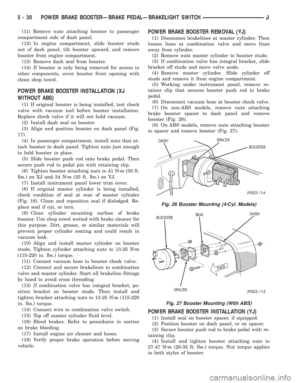
(7) On non-ABS models, remove nuts attaching
brake booster spacer to dash panel and remove
booster (Fig. 26).
(8) On ABS models, remove nuts attaching booster
to spacer and remove booster (Fig. 27).
POWER BRAKE BOOSTER INSTALLATION (YJ)
(1) Install seal on booster spacer, if equipped.
(2) Position booster on dash panel, or on spacer.
(3) Secure booster push rod to brake pedal with re-
taining clip.
(4) Install and tighten booster attaching nuts to
27-47 Nzm (20-35 ft. lbs.) torque. Nut torque applies
to both styles of booster.
Fig. 26 Booster Mounting (4-Cyl. Models)
Fig. 27 Booster Mounting (With ABS)
5 - 30 POWER BRAKE BOOSTERÐBRAKE PEDALÐBRAKELIGHT SWITCHJ
Page 183 of 2158
(5) Connect vacuum hose to brake booster check
valve.
(6) Install master cylinder and combination valve.
(7) Bleed brakes. Then tighten brakeline fittings to
15-18 Nzm (130-160 in. lbs.) at master cylinder and
18-24 Nzm (160-210 in. lbs.) at combination valve.
BRAKE PEDAL REMOVAL
(1) Remove lower trim panel and A/C duct if nec-
essary.
(2) Remove steering column lower trim panel and
bezel.(3) Remove necessary dash panel-to-instrument
panel brace rods.
(4) Disconnect and remove brakelight switch.
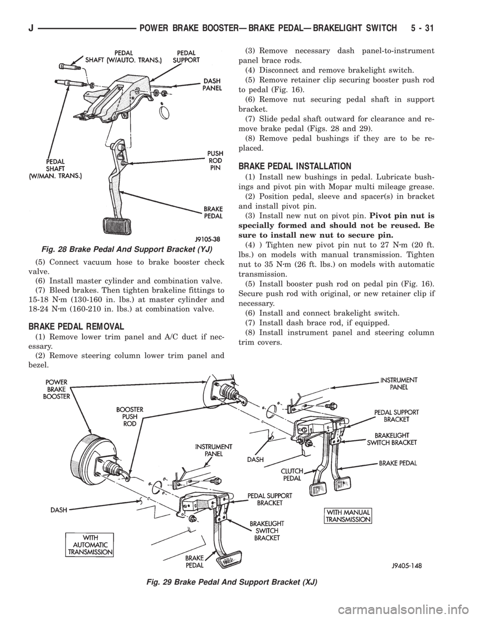
(5) Remove retainer clip securing booster push rod
to pedal (Fig. 16).
(6) Remove nut securing pedal shaft in support
bracket.
(7) Slide pedal shaft outward for clearance and re-
move brake pedal (Figs. 28 and 29).
(8) Remove pedal bushings if they are to be re-
placed.
BRAKE PEDAL INSTALLATION
(1) Install new bushings in pedal. Lubricate bush-
ings and pivot pin with Mopar multi mileage grease.
(2) Position pedal, sleeve and spacer(s) in bracket
and install pivot pin.
(3) Install new nut on pivot pin.Pivot pin nut is
specially formed and should not be reused. Be
sure to install new nut to secure pin.
(4) ) Tighten new pivot pin nut to 27 Nzm (20 ft.
lbs.) on models with manual transmission. Tighten
nut to 35 Nzm (26 ft. lbs.) on models with automatic
transmission.
(5) Install booster push rod on pedal pin (Fig. 16).
Secure push rod with original, or new retainer clip if
necessary.
(6) Install and connect brakelight switch.
(7) Install dash brace rod, if equipped.
(8) Install instrument panel and steering column
trim covers.
Fig. 28 Brake Pedal And Support Bracket (YJ)
Fig. 29 Brake Pedal And Support Bracket (XJ)
JPOWER BRAKE BOOSTERÐBRAKE PEDALÐBRAKELIGHT SWITCH 5 - 31
Page 185 of 2158

ABS OPERATION AND SERVICE
INDEX
page page
ABS Component Serviceability............... 37
ABS Diagnostic Connector.................. 35
ABS Operation in Antilock Braking Mode........ 36
ABS Operation in Normal Braking Mode........ 35
ABS System Power-Up and Initialization........ 35
Acceleration Switch........................ 35
Acceleration Switch Installation............... 39
Acceleration Switch Operation................ 37
Acceleration Switch Removal................ 39
Combination Valve........................ 34
ECU Installation (XJ Models)................. 40
ECU Operation........................... 37
ECU Removal (XJ Models).................. 40
ECU Removal/Installation (YJ Models).......... 41
Electronic Control Unit (ECU)................ 34
Front Wheel Sensor Installation............... 38
Front Wheel Sensor Removal................ 38HCU Installation (XJ)....................... 43
HCU Installation (YJ)....................... 44
HCU Operation........................... 36
HCU Removal (XJ)........................ 41
HCU Removal (YJ)........................ 44
Hydraulic Control Unit (HCU)................. 33
Ignition Switch........................... 35
Master Cylinder/Power Brake Booster.......... 34
Rear Wheel Sensor Installation and Adjustment . . . 38
Rear Wheel Sensor Removal................ 38
Speed Sensor Air Gap..................... 37
System Description........................ 33
System Relays........................... 35
System Warning Light...................... 35
Wheel Speed Sensor Operation.............. 37
Wheel Speed Sensors..................... 34
SYSTEM DESCRIPTION
The Jeep antilock brake system (ABS) is an elec-
tronically operated, all wheel brake control system.
The system is designed to prevent wheel lockup
and maintain steering control during periods of high
wheel slip when braking. Preventing lockup is accom-
plished by modulating fluid pressure to the wheel
brake units.
The hydraulic system is a three channel design.
The front wheel brakes are controlled individually
and the rear wheel brakes in tandem (Fig. 1). The
ABS electrical system is separate from other electri-
cal circuits in the vehicle. A specially programmed
electronic control unit (ECU) operates the system
components.
ABS system major components include:
²hydraulic control unit (HCU)
²electronic control unit (ECU)
²wheel speed sensors and axle shaft tone rings
²acceleration switch
²main relay and pump motor relay
²ABS warning light
²pump motor sensor
HYDRAULIC CONTROL UNIT (HCU)
The hydraulic control unit (HCU) consists of a
valve body, pump body, accumulators, pump motor,
and wire harnesses (Fig. 2).
The pump, motor, and accumulators are combined
into an assembly attached to the valve body. The ac-
cumulators store the extra fluid released to the sys-
tem for ABS mode operation. The pump provides the
fluid volume needed and is operated by a DC type
motor. The motor is controlled by the ECU.The valve body contains the solenoid valves. The
valves modulate brake pressure during antilock brak-
ing and are controlled by the ECU.
The HCU provides three channel pressure control
to the front and rear brakes. One channel controls
the rear wheel brakes in tandem. The two remaining
channels control the front wheel brakes individually.
During antilock braking, the solenoid valves are
opened and closed as needed. The valves are not static.
They are cycled rapidly and continuously to modulate
pressure and control wheel slip and deceleration.
Fig. 1 Jeep ABS System
JABS OPERATION AND SERVICE 5 - 33
Page 188 of 2158

During normal braking, the master cylinder, power
booster and wheel brake units all function as they
would in a vehicle without ABS. The HCU compo-
nents are not activated.
ABS OPERATION IN ANTILOCK BRAKING MODE
The purpose of the antilock system is to prevent
wheel lockup during periods of high wheel slip. Pre-
venting lockup helps maintain vehicle braking action
and steering control.
The antilock ECU activates the system whenever
sensor signals indicate periods of high wheel slip.
High wheel slip can be described as the point where
wheel rotation begins approaching zero (or lockup)
during braking. Periods of high wheel slip may occur
when brake stops involve high pedal pressure and
rate of deceleration.
The antilock system prevents lockup during high
slip conditions by modulating fluid apply pressure to
the wheel brake units.
Brake fluid apply pressure is modulated according
to wheel speed, degree of slip and rate of decelera-
tion. A sensor at each wheel converts wheel speed
into electrical signals. These signals are transmitted
to the ECU for processing and determination of
wheel slip and deceleration rate.
The ABS system has three fluid pressure control
channels. The front brakes are controlled separately
and the rear brakes in tandem (Fig. 1). A speed sen-
sor input signal indicating a high slip condition acti-
vates the ECU antilock program.
Two solenoid valves are used in each antilock con-
trol channel. The valves are all located within the
HCU valve body and work in pairs to either increase,
hold, or decrease apply pressure as needed in the in-
dividual control channels.
The solenoid valves are not static during antilock
braking. They are cycled continuously to modulate
pressure. Solenoid cycle time in antilock mode can be
measured in milliseconds.
HCU OPERATION
Normal Braking
During normal braking, the HCU solenoid valves
and pump are not activated. The master cylinder and
power booster operate the same as a vehicle without
an ABS brake system.
Antilock Pressure Modulation
Solenoid valve pressure modulation occurs in three
stages which are: pressure increase, pressure hold,
and pressure decrease. The valves are all contained
in the valve body portion of the HCU.
Pressure Decrease
The outlet valve is opened and the inlet valve is
closed during the pressure decrease cycle (Fig. 6).A pressure decrease cycle is initiated when speed
sensor signals indicate high wheel slip at one or
more wheels. At this point, the ECU opens the outlet
valve, which also opens the return circuit to the ac-
cumulators. Fluid pressure is allowed to bleed off (de-
crease) as needed to prevent wheel lock.
Once the period of high wheel slip has ended, the
ECU closes the outlet valve and begins a pressure in-
crease or hold cycle as needed.
Pressure Hold
Both solenoid valves are closed in the pressure hold
cycle (Fig. 7). Fluid apply pressure in the control
channel is maintained at a constant rate. The ECU
maintains the hold cycle until sensor inputs indicate
a pressure change is necessary.
Pressure Increase
The inlet valve is open and the outlet valve is
closed during the pressure increase cycle (Fig. 8). The
pressure increase cycle is used to counteract unequal
wheel speeds. This cycle controls re-application of
fluid apply pressure due to changing road surfaces or
wheel speed.
Fig. 6 Pressure Decrease Cycle
5 - 36 ABS OPERATION AND SERVICEJ
Page 194 of 2158
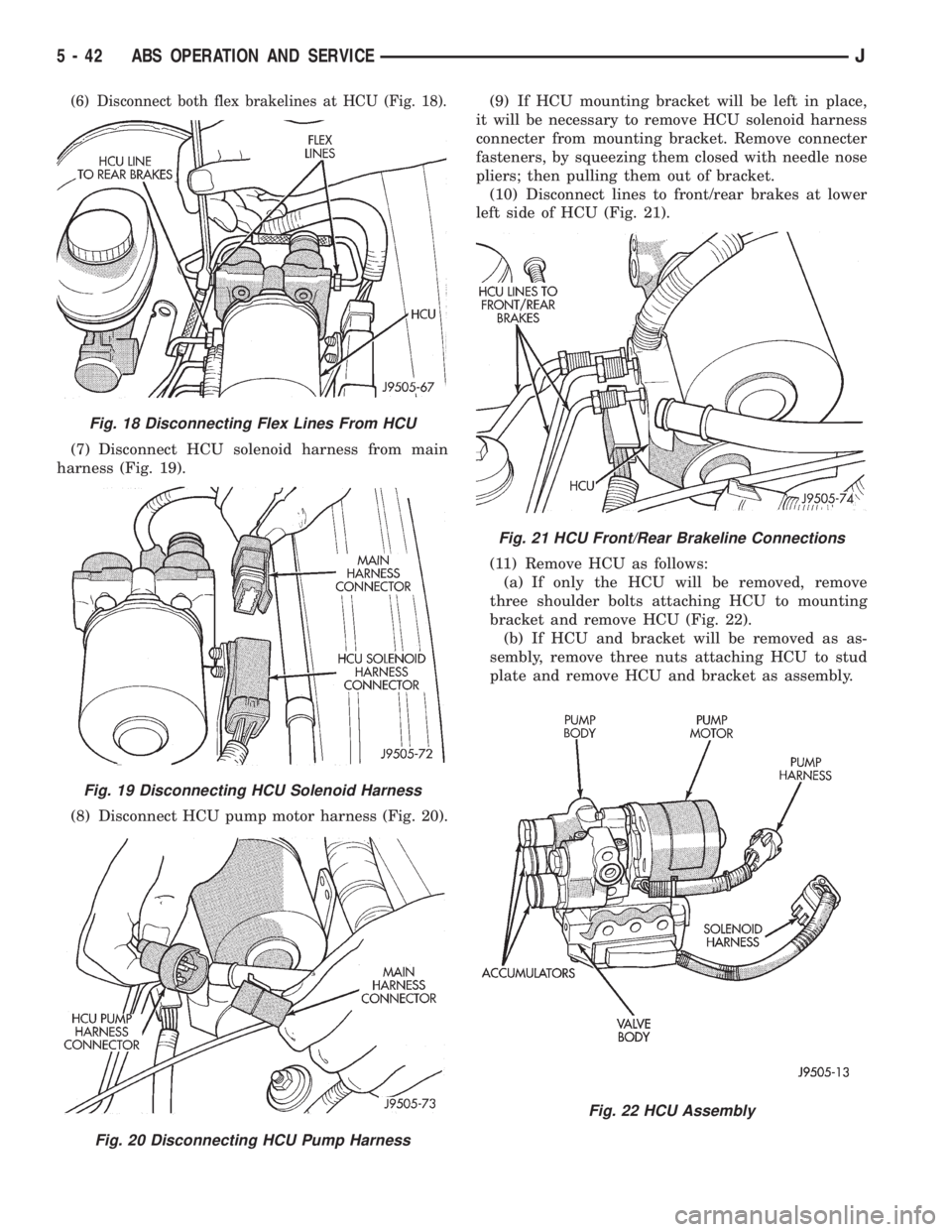
(6) Disconnect both flex brakelines at HCU (Fig. 18).
(7) Disconnect HCU solenoid harness from main
harness (Fig. 19).
(8) Disconnect HCU pump motor harness (Fig. 20).(9) If HCU mounting bracket will be left in place,
it will be necessary to remove HCU solenoid harness
connecter from mounting bracket. Remove connecter
fasteners, by squeezing them closed with needle nose
pliers; then pulling them out of bracket.
(10) Disconnect lines to front/rear brakes at lower
left side of HCU (Fig. 21).
(11) Remove HCU as follows:
(a) If only the HCU will be removed, remove
three shoulder bolts attaching HCU to mounting
bracket and remove HCU (Fig. 22).
(b) If HCU and bracket will be removed as as-
sembly, remove three nuts attaching HCU to stud
plate and remove HCU and bracket as assembly.
Fig. 18 Disconnecting Flex Lines From HCU
Fig. 19 Disconnecting HCU Solenoid Harness
Fig. 20 Disconnecting HCU Pump Harness
Fig. 21 HCU Front/Rear Brakeline Connections
Fig. 22 HCU Assembly
5 - 42 ABS OPERATION AND SERVICEJ
Page 195 of 2158
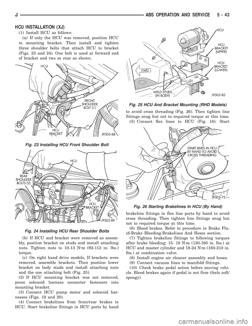
HCU INSTALLATION (XJ)
(1) Install HCU as follows:
(a) If only the HCU was removed, position HCU
in mounting bracket. Then install and tighten
three shoulder bolts that attach HCU to bracket
(Figs. 23 and 24). One bolt is used at forward end
of bracket and two at rear as shown.
(b) If HCU and bracket were removed as assem-
bly, position bracket on studs and install attaching
nuts. Tighten nuts to 10-13 Nzm (92-112 in. lbs.)
torque.
(c) On right hand drive models, If brackets were
removed, assemble brackets. Then position lower
bracket on body studs and install attaching nuts
and the one attaching bolt (Fig. 25).
(2) If HCU mounting bracket was not removed,
press solenoid harness connecter fasteners into
mounting bracket.
(3) Connect HCU pump motor and solenoid har-
nesses (Figs. 19 and 20).
(4) Connect brakelines from front/rear brakes to
HCU. Start brakeline fittings in HCU ports by handto avoid cross threading (Fig. 26). Then tighten line
fittings snug but not to required torque at this time.
(5) Connect flex lines to HCU (Fig. 18). Start
brakeline fittings in flex line ports by hand to avoid
cross threading. Then tighten line fittings snug but
not to required torque at this time.
(6) Bleed brakes. Refer to procedure in Brake Flu-
id-Brake Bleeding-Brakelines And Hoses section.
(7) Tighten brakeline fittings to following torques
after brake bleeding: 15- 18 Nzm (130-160 in. lbs.) at
HCU and master cylinder and 18-24 Nzm (160-210 in.
lbs.) at combination valve.
(8) Install engine air cleaner assembly and hoses.
(9) Connect vacuum lines to manifold fittings.
(10) Check brake pedal action before moving vehi-
cle. Bleed brakes again if pedal is not firm (feels soft/
spongy).
Fig. 23 Installing HCU Front Shoulder Bolt
Fig. 24 Installing HCU Rear Shoulder Bolts
Fig. 25 HCU And Bracket Mounting (RHD Models)
Fig. 26 Starting Brakelines In HCU (By Hand)
JABS OPERATION AND SERVICE 5 - 43