1995 JEEP YJ wheel
[x] Cancel search: wheelPage 1917 of 2158
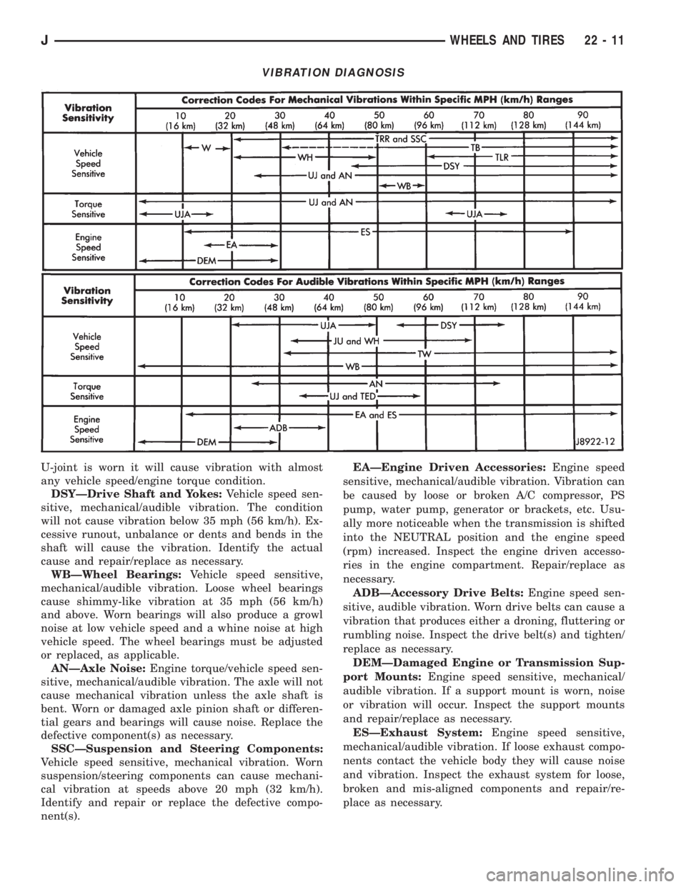
U-joint is worn it will cause vibration with almost
any vehicle speed/engine torque condition.
DSYÐDrive Shaft and Yokes:Vehicle speed sen-
sitive, mechanical/audible vibration. The condition
will not cause vibration below 35 mph (56 km/h). Ex-
cessive runout, unbalance or dents and bends in the
shaft will cause the vibration. Identify the actual
cause and repair/replace as necessary.
WBÐWheel Bearings:Vehicle speed sensitive,
mechanical/audible vibration. Loose wheel bearings
cause shimmy-like vibration at 35 mph (56 km/h)
and above. Worn bearings will also produce a growl
noise at low vehicle speed and a whine noise at high
vehicle speed. The wheel bearings must be adjusted
or replaced, as applicable.
ANÐAxle Noise:Engine torque/vehicle speed sen-
sitive, mechanical/audible vibration. The axle will not
cause mechanical vibration unless the axle shaft is
bent. Worn or damaged axle pinion shaft or differen-
tial gears and bearings will cause noise. Replace the
defective component(s) as necessary.
SSCÐSuspension and Steering Components:
Vehicle speed sensitive, mechanical vibration. Worn
suspension/steering components can cause mechani-
cal vibration at speeds above 20 mph (32 km/h).
Identify and repair or replace the defective compo-
nent(s).EAÐEngine Driven Accessories:Engine speed
sensitive, mechanical/audible vibration. Vibration can
be caused by loose or broken A/C compressor, PS
pump, water pump, generator or brackets, etc. Usu-
ally more noticeable when the transmission is shifted
into the NEUTRAL position and the engine speed
(rpm) increased. Inspect the engine driven accesso-
ries in the engine compartment. Repair/replace as
necessary.
ADBÐAccessory Drive Belts:Engine speed sen-
sitive, audible vibration. Worn drive belts can cause a
vibration that produces either a droning, fluttering or
rumbling noise. Inspect the drive belt(s) and tighten/
replace as necessary.
DEMÐDamaged Engine or Transmission Sup-
port Mounts:Engine speed sensitive, mechanical/
audible vibration. If a support mount is worn, noise
or vibration will occur. Inspect the support mounts
and repair/replace as necessary.
ESÐExhaust System:Engine speed sensitive,
mechanical/audible vibration. If loose exhaust compo-
nents contact the vehicle body they will cause noise
and vibration. Inspect the exhaust system for loose,
broken and mis-aligned components and repair/re-
place as necessary.
VIBRATION DIAGNOSIS
JWHEELS AND TIRES 22 - 11
Page 1918 of 2158
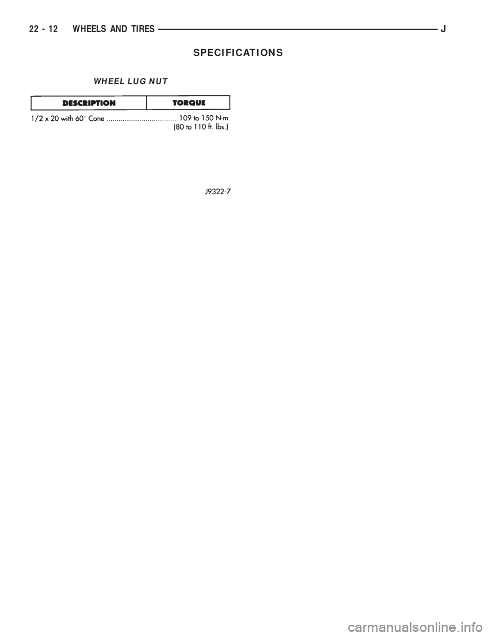
SPECIFICATIONS
WHEEL LUG NUT
22 - 12 WHEELS AND TIRESJ
Page 1921 of 2158
EXTERIOR COMPONENTS
INDEX
page page
Air Exhaust GrilleÐXJ...................... 25
Battery TrayÐXJ.......................... 14
Body Side Molding/CladdingÐXJ.............. 20
Body Stripes/DecalsÐXJ.................... 21
Brush GuardÐXJ.......................... 3
Cowl Grille and ScreenÐXJ................. 12
Cowl Weatherstrip Seal/Crossmember Air
DeflectorÐXJ........................... 11
Dash Panel Insulator PanelÐXJ.............. 12
Drip Rail MoldingÐXJ...................... 25
Exterior NameplatesÐXJ................... 26
External MirrorsÐXJ....................... 27
Front FenderÐXJ......................... 14
Fuel Filler Door BumpersÐXJ................ 27Fuel Filler Nozzle/TubeÐXJ................. 26
Grille and Grille Opening Panel (GOP)ÐXJ....... 3
Hood AdjustmentÐXJ...................... 10
Hood Hinge ReplacementÐXJ............... 10
Hood Latch ReplacementÐXJ................ 11
Hood Latch Striker ReplacementÐXJ.......... 11
HoodÐXJ................................ 7
Latch Release Cable ReplacementÐXJ......... 11
Luggage RackÐXJ........................ 28
Quarter Window AppliqueÐXJ................ 25
Radiator Support CrossmemberÐXJ............ 6
Rear Wheelhouse Flares and LinersÐXJ........ 19
Safety Latch Striker ReplacementÐXJ.......... 11
BRUSH GUARDÐXJ
REMOVAL
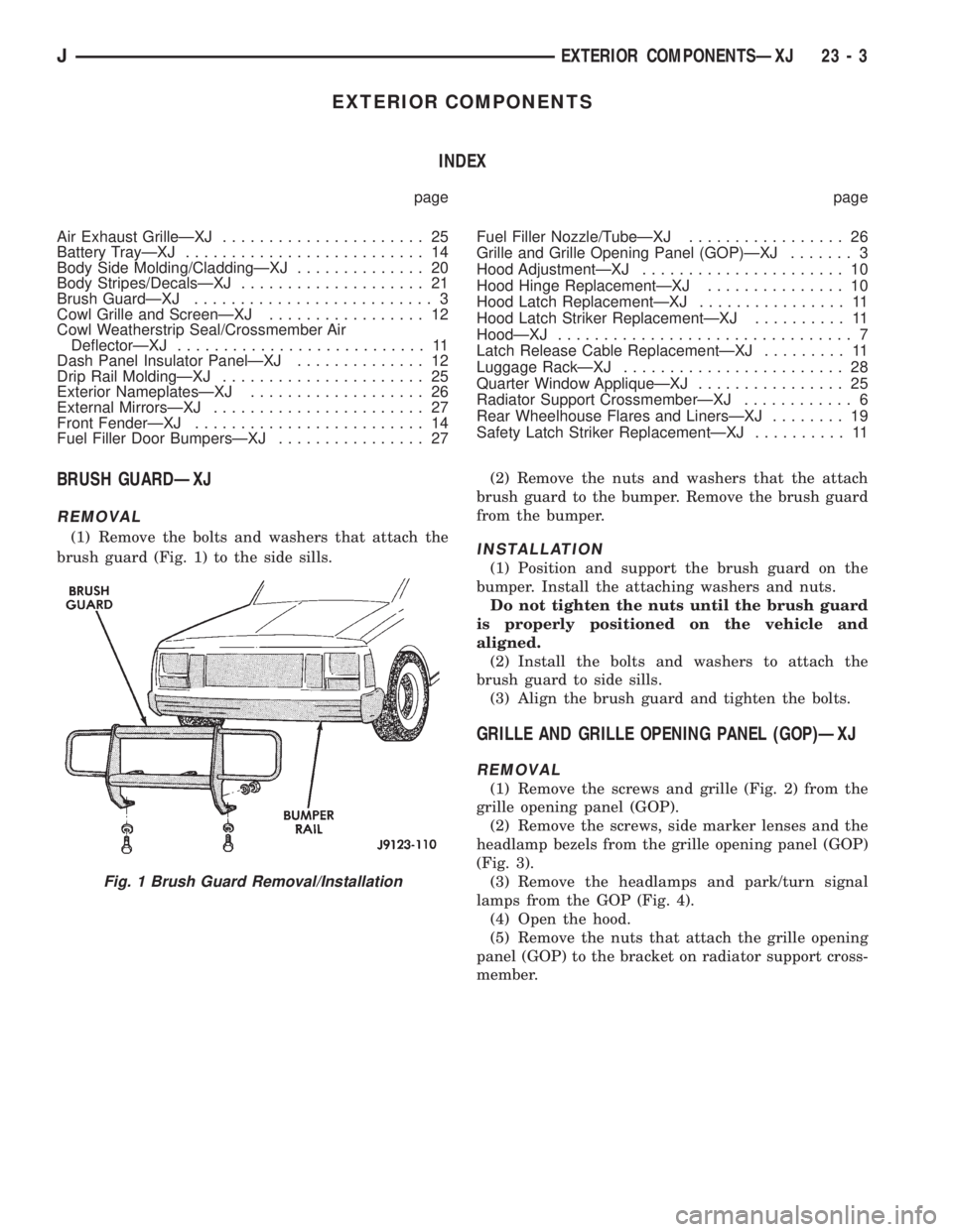
(1) Remove the bolts and washers that attach the
brush guard (Fig. 1) to the side sills.(2) Remove the nuts and washers that the attach
brush guard to the bumper. Remove the brush guard
from the bumper.INSTALLATION
(1) Position and support the brush guard on the
bumper. Install the attaching washers and nuts.
Do not tighten the nuts until the brush guard
is properly positioned on the vehicle and
aligned.
(2) Install the bolts and washers to attach the
brush guard to side sills.
(3) Align the brush guard and tighten the bolts.
GRILLE AND GRILLE OPENING PANEL (GOP)ÐXJ
REMOVAL
(1) Remove the screws and grille (Fig. 2) from the
grille opening panel (GOP).
(2) Remove the screws, side marker lenses and the
headlamp bezels from the grille opening panel (GOP)
(Fig. 3).
(3) Remove the headlamps and park/turn signal
lamps from the GOP (Fig. 4).
(4) Open the hood.
(5) Remove the nuts that attach the grille opening
panel (GOP) to the bracket on radiator support cross-
member.
Fig. 1 Brush Guard Removal/Installation
JEXTERIOR COMPONENTSÐXJ 23 - 3
Page 1935 of 2158
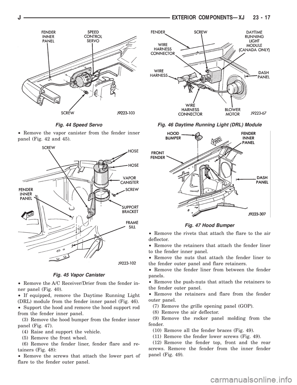
²Remove the vapor canister from the fender inner
panel (Fig. 42 and 45).
²Remove the A/C Receiver/Drier from the fender in-
ner panel (Fig. 40).
²If equipped, remove the Daytime Running Light
(DRL) module from the fender inner panel (Fig. 46).
²Support the hood and remove the hood support rod
from the fender inner panel.
(3) Remove the hood bumper from the fender inner
panel (Fig. 47).
(4) Raise and support the vehicle.
(5) Remove the front wheel.
(6) Remove the fender liner, fender flare and re-
tainers (Fig. 48):
²Remove the screws that attach the lower part of
flare to the fender outer panel.²Remove the rivets that attach the flare to the air
deflector.
²Remove the retainers that attach the fender liner
to the fender inner panel.
²Remove the nuts that attach the fender liner to
the fender outer panel and flare retainers.
²Remove the fender liner from between the fender
panels.
²Remove the push-nuts that attach the retainers to
the fender outer panel.
²Remove the retainers and flare from the fender
outer panel.
(7) Remove the grille opening panel (GOP).
(8) Remove the air deflector.
(9) Remove the rocker panel molding from the
fender.
(10) Remove all the fender braces (Fig. 49).
(11) Remove the fender lower screws (Fig. 49).
(12) Remove the fender top, front and the rear
screws. Remove the fender from the inner fender
panel (Fig. 49).
Fig. 44 Speed Servo
Fig. 45 Vapor Canister
Fig. 46 Daytime Running Light (DRL) Module
Fig. 47 Hood Bumper
JEXTERIOR COMPONENTSÐXJ 23 - 17
Page 1937 of 2158
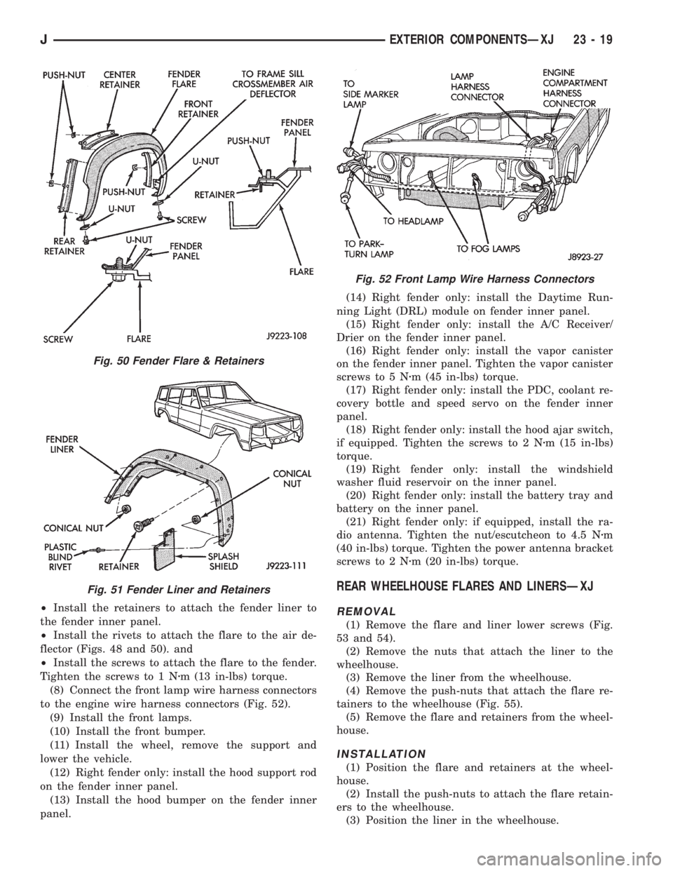
²Install the retainers to attach the fender liner to
the fender inner panel.
²Install the rivets to attach the flare to the air de-
flector (Figs. 48 and 50). and
²Install the screws to attach the flare to the fender.
Tighten the screws to 1 Nzm (13 in-lbs) torque.
(8) Connect the front lamp wire harness connectors
to the engine wire harness connectors (Fig. 52).
(9) Install the front lamps.
(10) Install the front bumper.
(11) Install the wheel, remove the support and
lower the vehicle.
(12) Right fender only: install the hood support rod
on the fender inner panel.
(13) Install the hood bumper on the fender inner
panel.(14) Right fender only: install the Daytime Run-
ning Light (DRL) module on fender inner panel.
(15) Right fender only: install the A/C Receiver/
Drier on the fender inner panel.
(16) Right fender only: install the vapor canister
on the fender inner panel. Tighten the vapor canister
screws to 5 Nzm (45 in-lbs) torque.
(17) Right fender only: install the PDC, coolant re-
covery bottle and speed servo on the fender inner
panel.
(18) Right fender only: install the hood ajar switch,
if equipped. Tighten the screws to 2 Nzm (15 in-lbs)
torque.
(19) Right fender only: install the windshield
washer fluid reservoir on the inner panel.
(20) Right fender only: install the battery tray and
battery on the inner panel.
(21) Right fender only: if equipped, install the ra-
dio antenna. Tighten the nut/escutcheon to 4.5 Nzm
(40 in-lbs) torque. Tighten the power antenna bracket
screws to 2 Nzm (20 in-lbs) torque.
REAR WHEELHOUSE FLARES AND LINERSÐXJ
REMOVAL
(1) Remove the flare and liner lower screws (Fig.
53 and 54).
(2) Remove the nuts that attach the liner to the
wheelhouse.
(3) Remove the liner from the wheelhouse.
(4) Remove the push-nuts that attach the flare re-
tainers to the wheelhouse (Fig. 55).
(5) Remove the flare and retainers from the wheel-
house.
INSTALLATION
(1) Position the flare and retainers at the wheel-
house.
(2) Install the push-nuts to attach the flare retain-
ers to the wheelhouse.
(3) Position the liner in the wheelhouse.
Fig. 50 Fender Flare & Retainers
Fig. 51 Fender Liner and Retainers
Fig. 52 Front Lamp Wire Harness Connectors
JEXTERIOR COMPONENTSÐXJ 23 - 19
Page 1938 of 2158
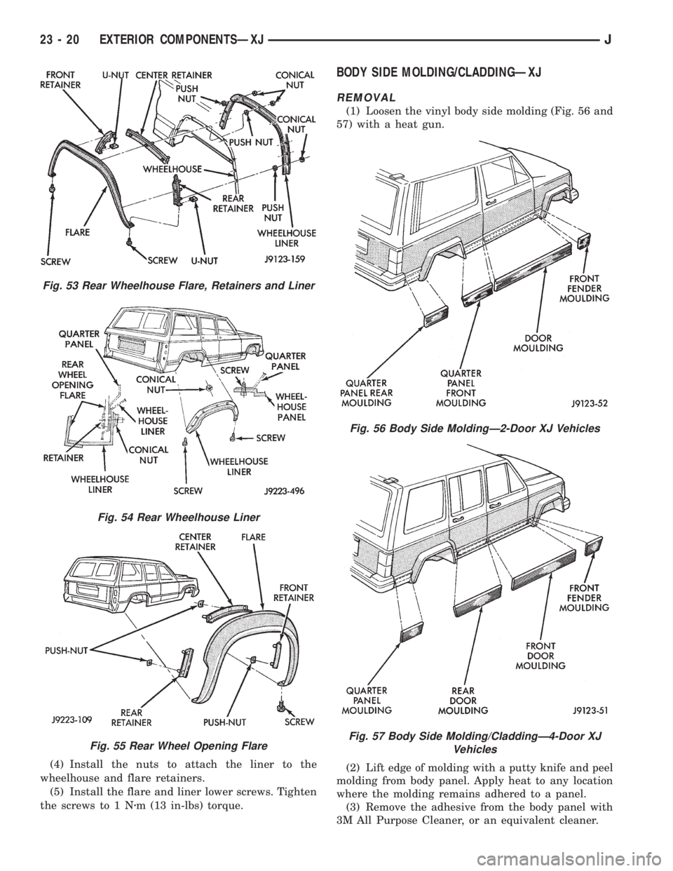
(4) Install the nuts to attach the liner to the
wheelhouse and flare retainers.
(5) Install the flare and liner lower screws. Tighten
the screws to 1 Nzm (13 in-lbs) torque.
BODY SIDE MOLDING/CLADDINGÐXJ
REMOVAL
(1) Loosen the vinyl body side molding (Fig. 56 and
57) with a heat gun.
(2) Lift edge of molding with a putty knife and peel
molding from body panel. Apply heat to any location
where the molding remains adhered to a panel.
(3) Remove the adhesive from the body panel with
3M All Purpose Cleaner, or an equivalent cleaner.
Fig. 53 Rear Wheelhouse Flare, Retainers and Liner
Fig. 54 Rear Wheelhouse Liner
Fig. 55 Rear Wheel Opening Flare
Fig. 56 Body Side MoldingÐ2-Door XJ Vehicles
Fig. 57 Body Side Molding/CladdingÐ4-Door XJ
Vehicles
23 - 20 EXTERIOR COMPONENTSÐXJJ
Page 1998 of 2158
INTERIOR COMPONENTS
INDEX
page page
Assist HandleÐXJ........................ 89
B/C-Pillar and Liftgate Pillar Trim CoversÐXJ.... 88
Bucket Seat Cushion and CoverÐXJ........... 81
Bucket Seat PlatformÐXJ................... 82
Bucket Seatback Cover and FrameÐXJ........ 81
Cargo BarrierÐXJ........................ 101
Cargo LampÐXJ......................... 94
Carpets and Floor MatsÐXJ................. 99
Dome LampÐXJ......................... 93
Front Bucket SeatsÐXJ.................... 81
Front Carpet/MatÐXJ...................... 99
Front Inner Scuff Plate/Cowl Side Trim PanelÐXJ . 86
Front Shoulder Belt/BuckleÐXJ............... 90
Full Floor ConsoleÐXJ..................... 95
HeadlinerÐXJ............................ 92
I/P Ash Receiver Tray LampÐXJ.............. 80
Instrument Cluster BezelÐXJ................ 80
Interior Trim Panels and Scuff PlatesÐXJ....... 84
Jack StorageÐXJ......................... 97
Keyless Entry ReceiverÐXJ................. 93Mini-Console with Floor ShiftÐXJ............. 94
Mini-Floor ConsoleÐXJ..................... 94
Outer Scuff PlatesÐXJ..................... 89
Overhead ConsoleÐXJ..................... 93
Parking Brake Handle CoverÐXJ............. 94
Quarter and Wheelhouse Trim PanelsÐXJ...... 87
Quarter Trim Panel ExtensionÐXJ............. 87
Rear Carpet/MatÐXJ..................... 100
Rear Seat Cushion CoverÐXJ............... 82
Rear Seat CushionÐXJ.................... 82
Rear Seatback CoverÐXJ................... 84
Rear Seatback Latch Striker and BumperÐXJ.... 84
Rear SeatbackÐXJ........................ 83
Rear Shoulder/Lap Belt/BuckleÐXJ............ 91
Sound BarÐXJ........................... 94
Spare Tire/Wheel Holddown and Floor
BracketsÐXJ........................... 98
SunvisorsÐXJ........................... 93
Windshield Side MoldingÐXJ................ 86
INSTRUMENT CLUSTER BEZELÐXJ
REMOVAL
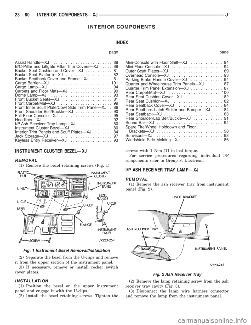
(1) Remove the bezel retaining screws (Fig. 1).
(2) Separate the bezel from the U-clips and remove
it from the upper section of the instrument panel.
(3) If necessary, remove or install rocker switch
cover plates.
INSTALLATION
(1) Position the bezel on the upper instrument
panel and engage it with the U-clips.
(2) Install the bezel retaining screws. Tighten thescrews with 1 Nzm (11 in-lbs) torque.
For service procedures regarding individual I/P
components refer to Group 8, Electrical.
I/P ASH RECEIVER TRAY LAMPÐXJ
REMOVAL
(1) Remove the ash receiver tray from instrument
panel (Fig. 2).
(2) Remove the lamp retaining screw from the ash
receiver tray cavity (Fig. 3).
(3) Disconnect the lamp wire harness connector
and remove the lamp from the instrument panel.
Fig. 1 Instrument Bezel Removal/Installation
Fig. 2 Ash Receiver Tray
23 - 80 INTERIOR COMPONENTSÐXJJ
Page 2001 of 2158
INSTALLATION
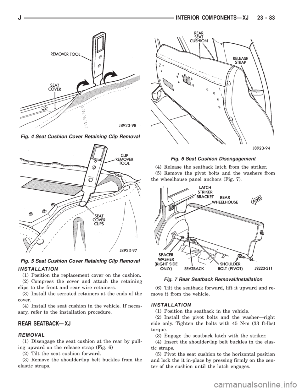
(1) Position the replacement cover on the cushion.
(2) Compress the cover and attach the retaining
clips to the front and rear wire retainers.
(3) Install the serrated retainers at the ends of the
cover.
(4) Install the seat cushion in the vehicle. If neces-
sary, refer to the installation procedure.
REAR SEATBACKÐXJ
REMOVAL
(1) Disengage the seat cushion at the rear by pull-
ing upward on the release strap (Fig. 6)
(2) Tilt the seat cushion forward.
(3) Remove the shoulder/lap belt buckles from the
elastic straps.(4) Release the seatback latch from the striker.
(5) Remove the pivot bolts and the washers from
the wheelhouse panel anchors (Fig. 7).
(6) Tilt the seatback forward, lift it upward and re-
move it from the vehicle.
INSTALLATION
(1) Position the seatback in the vehicle.
(2) Install the pivot bolts and the washerÐright
side only. Tighten the bolts with 45 Nzm (33 ft-lbs)
torque.
(3) Engage the seatback latch with the striker.
(4) Insert the shoulder/lap belt buckles in the elas-
tic straps.
(5) Pivot the seat cushion to the horizontal position
and lock the it in-place by pressing firmly on the cen-
ter of the cushion until the latch engages.
Fig. 4 Seat Cushion Cover Retaining Clip Removal
Fig. 5 Seat Cushion Cover Retaining Clip Removal
Fig. 6 Seat Cushion Disengagement
Fig. 7 Rear Seatback Removal/Installation
JINTERIOR COMPONENTSÐXJ 23 - 83