1995 JEEP YJ wheel
[x] Cancel search: wheelPage 2005 of 2158
(2) Install the headliner front trim molding, the
cowl side trim panel and the inner scuff plate in the
interior of the vehicle. Tighten the retaining screw to
1Nzm (11 in-lbs) torque.
QUARTER TRIM PANEL EXTENSIONÐXJ
REMOVAL
(1) Remove the retaining screws and the inner
scuff plate from the door sill.
(2) Remove the retaining screws and serrated re-
tainers, and remove the panel extension from the
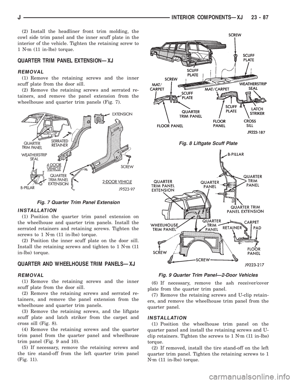
wheelhouse and quarter trim panels (Fig. 7).
INSTALLATION
(1) Position the quarter trim panel extension on
the wheelhouse and quarter trim panels. Install the
serrated retainers and retaining screws. Tighten the
screws to 1 Nzm (11 in-lbs) torque.
(2) Position the inner scuff plate on the door sill.
Install the retaining screws and tighten to 1 Nzm(11
in-lbs) torque.
QUARTER AND WHEELHOUSE TRIM PANELSÐXJ
REMOVAL
(1) Remove the retaining screws and the inner
scuff plate from the door sill.
(2) Remove the retaining screws and serrated re-
tainers, and remove the panel extension from the
wheelhouse and quarter trim panels.
(3) Remove the retaining screws, and the liftgate
scuff plate and latch striker from the carpet and
cross sill (Fig. 8).
(4) Remove the retaining screws and the quarter
trim panel from the quarter panel and wheelhouse
trim panel (Fig. 9 and 10).
(5) If necessary, remove the retaining screws and
the tire stand-off from the left quarter trim panel
(Fig. 11).(6) If necessary, remove the ash receiver/cover
plate from the quarter trim panel.
(7) Remove the retaining screws and U-clip retain-
ers, and remove the wheelhouse trim panel from the
quarter panel.
INSTALLATION
(1) Position the wheelhouse trim panel on the
quarter panel and install the retaining screws and U-
clip retainers. Tighten the screws to 1 Nzm (11 in-lbs)
torque.
(2) If removed, install the tire stand-off on the left
quarter trim panel. Tighten the retaining screws to 1
Nzm (11 in-lbs) torque.
Fig. 7 Quarter Trim Panel Extension
Fig. 8 Liftgate Scuff Plate
Fig. 9 Quarter Trim PanelÐ2-Door Vehicles
JINTERIOR COMPONENTSÐXJ 23 - 87
Page 2006 of 2158
(3) If removed, install the ash receiver/cover plate
on the quarter trim panel.
(4) Position the quarter trim panel on the quarter
panel and wheelhouse trim panel. Install and tighten
the retaining screws to 1 Nzm (11 in-lbs) torque.
(5) Position scuff plate and latch striker on the car-
pet and cross sill, and install the retaining screw-
s.Tighten the scuff plate screws to 1 Nzm (11 in-lbs)
torque. Tighten the latch striker screws to 30 Nzm
(22 ft-lbs) torque.
(6) Position the quarter trim panel extension on
the wheelhouse and quarter trim panels. Install the
serrated retainers and retaining screws. Tighten the
screws to 1 Nzm (11 in-lbs) torque.
(7) Position the inner scuff plate on the door sill.
Install the retaining screws and tighten to 1 Nzm(11
in-lbs) torque.
B/C-PILLAR AND LIFTGATE PILLAR TRIM
COVERSÐXJ
REMOVAL
(1) Remove the retaining screws and the inner
scuff plate from the door sill.(2) Remove the cowl side trim panel, the headliner
trim molding and the windshield side molding from
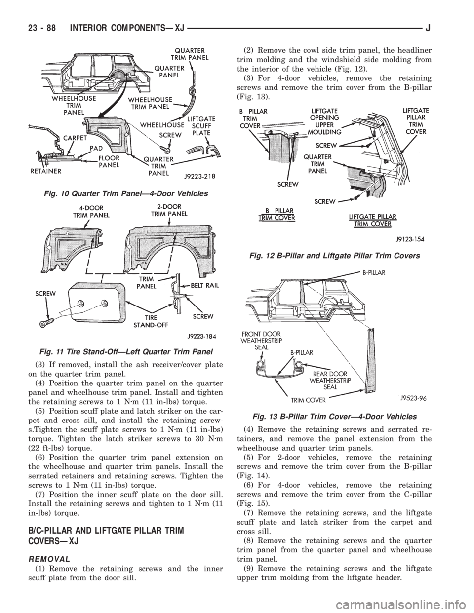
the interior of the vehicle (Fig. 12).
(3) For 4-door vehicles, remove the retaining
screws and remove the trim cover from the B-pillar
(Fig. 13).
(4) Remove the retaining screws and serrated re-
tainers, and remove the panel extension from the
wheelhouse and quarter trim panels.
(5) For 2-door vehicles, remove the retaining
screws and remove the trim cover from the B-pillar
(Fig. 14).
(6) For 4-door vehicles, remove the retaining
screws and remove the trim cover from the C-pillar
(Fig. 15).
(7) Remove the retaining screws, and the liftgate
scuff plate and latch striker from the carpet and
cross sill.
(8) Remove the retaining screws and the quarter
trim panel from the quarter panel and wheelhouse
trim panel.
(9) Remove the retaining screws and the liftgate
upper trim molding from the liftgate header.
Fig. 10 Quarter Trim PanelÐ4-Door Vehicles
Fig. 11 Tire Stand-OffÐLeft Quarter Trim Panel
Fig. 12 B-Pillar and Liftgate Pillar Trim Covers
Fig. 13 B-Pillar Trim CoverÐ4-Door Vehicles
23 - 88 INTERIOR COMPONENTSÐXJJ
Page 2007 of 2158
(10) Remove the retaining screws and the trim
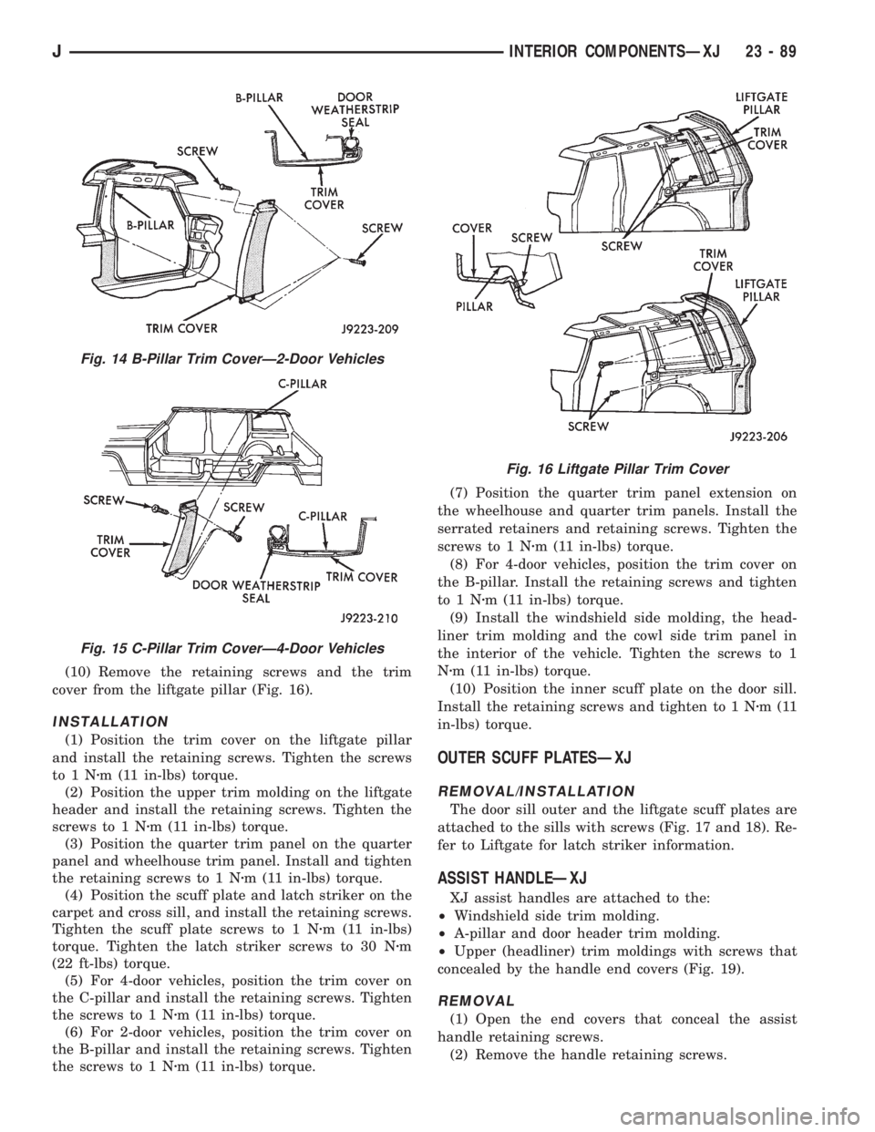
cover from the liftgate pillar (Fig. 16).
INSTALLATION
(1) Position the trim cover on the liftgate pillar
and install the retaining screws. Tighten the screws
to1Nzm (11 in-lbs) torque.
(2) Position the upper trim molding on the liftgate
header and install the retaining screws. Tighten the
screws to 1 Nzm (11 in-lbs) torque.
(3) Position the quarter trim panel on the quarter
panel and wheelhouse trim panel. Install and tighten
the retaining screws to 1 Nzm (11 in-lbs) torque.
(4) Position the scuff plate and latch striker on the
carpet and cross sill, and install the retaining screws.
Tighten the scuff plate screws to 1 Nzm (11 in-lbs)
torque. Tighten the latch striker screws to 30 Nzm
(22 ft-lbs) torque.
(5) For 4-door vehicles, position the trim cover on
the C-pillar and install the retaining screws. Tighten
the screws to 1 Nzm (11 in-lbs) torque.
(6) For 2-door vehicles, position the trim cover on
the B-pillar and install the retaining screws. Tighten
the screws to 1 Nzm (11 in-lbs) torque.(7) Position the quarter trim panel extension on
the wheelhouse and quarter trim panels. Install the
serrated retainers and retaining screws. Tighten the
screws to 1 Nzm (11 in-lbs) torque.
(8) For 4-door vehicles, position the trim cover on
the B-pillar. Install the retaining screws and tighten
to1Nzm (11 in-lbs) torque.
(9) Install the windshield side molding, the head-
liner trim molding and the cowl side trim panel in
the interior of the vehicle. Tighten the screws to 1
Nzm (11 in-lbs) torque.
(10) Position the inner scuff plate on the door sill.
Install the retaining screws and tighten to 1 Nzm(11
in-lbs) torque.
OUTER SCUFF PLATESÐXJ
REMOVAL/INSTALLATION
The door sill outer and the liftgate scuff plates are
attached to the sills with screws (Fig. 17 and 18). Re-
fer to Liftgate for latch striker information.
ASSIST HANDLEÐXJ
XJ assist handles are attached to the:
²Windshield side trim molding.
²A-pillar and door header trim molding.
²Upper (headliner) trim moldings with screws that
concealed by the handle end covers (Fig. 19).
REMOVAL
(1) Open the end covers that conceal the assist
handle retaining screws.
(2) Remove the handle retaining screws.
Fig. 14 B-Pillar Trim CoverÐ2-Door Vehicles
Fig. 15 C-Pillar Trim CoverÐ4-Door Vehicles
Fig. 16 Liftgate Pillar Trim Cover
JINTERIOR COMPONENTSÐXJ 23 - 89
Page 2016 of 2158
SPARE TIRE/WHEEL HOLDDOWN AND FLOOR
BRACKETSÐXJ
REMOVAL
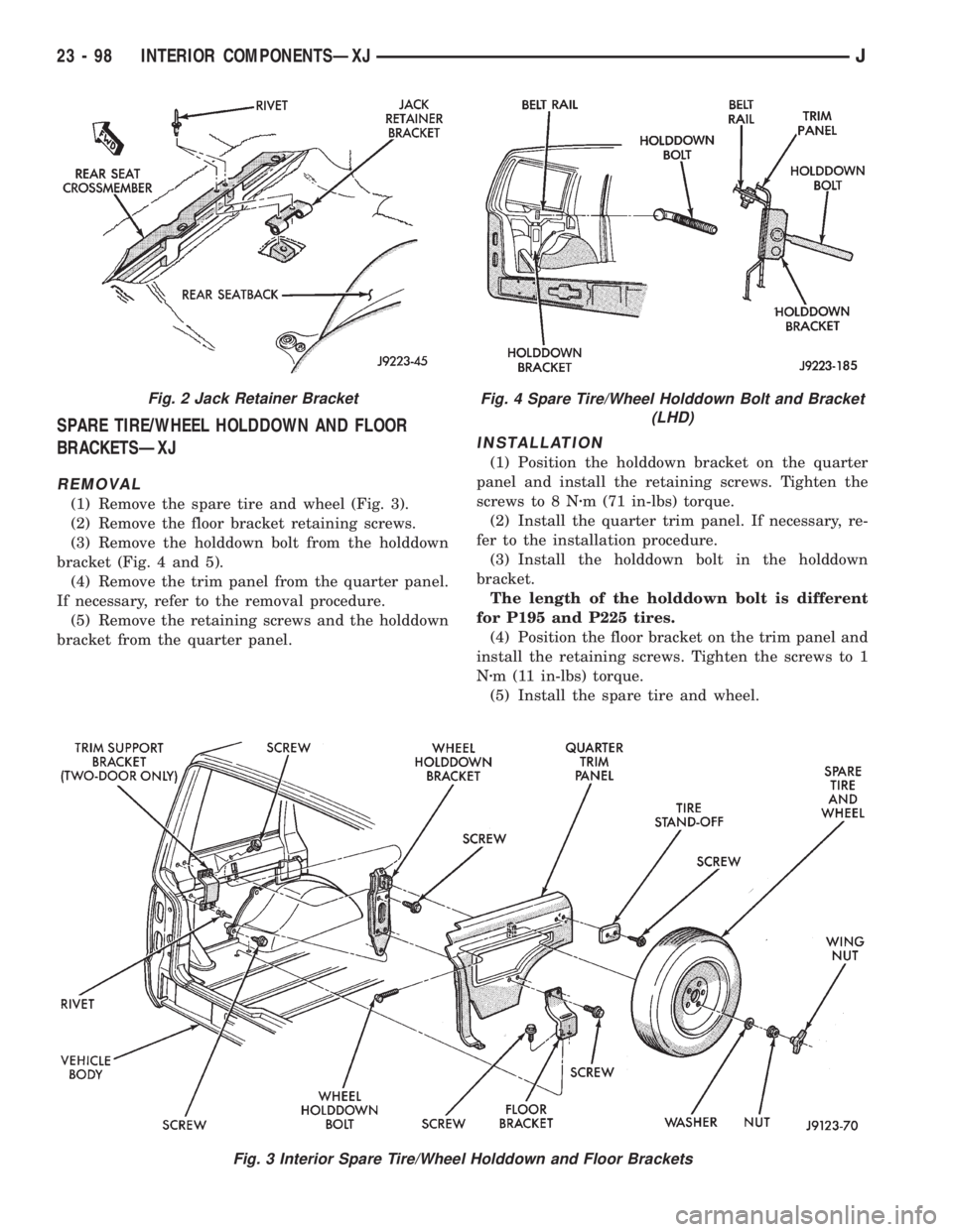
(1) Remove the spare tire and wheel (Fig. 3).
(2) Remove the floor bracket retaining screws.
(3) Remove the holddown bolt from the holddown
bracket (Fig. 4 and 5).
(4) Remove the trim panel from the quarter panel.
If necessary, refer to the removal procedure.
(5) Remove the retaining screws and the holddown
bracket from the quarter panel.
INSTALLATION
(1) Position the holddown bracket on the quarter
panel and install the retaining screws. Tighten the
screws to 8 Nzm (71 in-lbs) torque.
(2) Install the quarter trim panel. If necessary, re-
fer to the installation procedure.
(3) Install the holddown bolt in the holddown
bracket.
The length of the holddown bolt is different
for P195 and P225 tires.
(4) Position the floor bracket on the trim panel and
install the retaining screws. Tighten the screws to 1
Nzm (11 in-lbs) torque.
(5) Install the spare tire and wheel.
Fig. 3 Interior Spare Tire/Wheel Holddown and Floor Brackets
Fig. 2 Jack Retainer BracketFig. 4 Spare Tire/Wheel Holddown Bolt and Bracket
(LHD)
23 - 98 INTERIOR COMPONENTSÐXJJ
Page 2017 of 2158
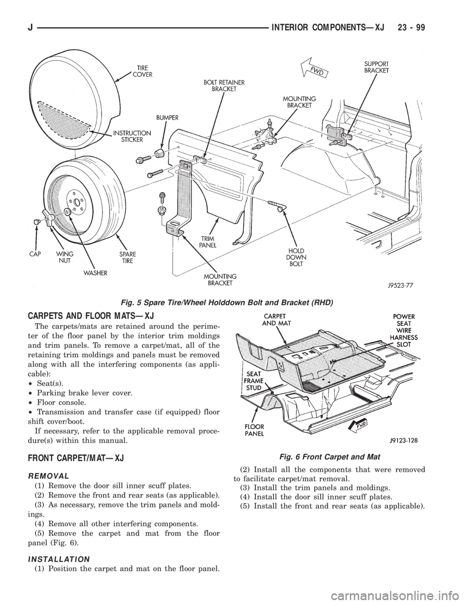
CARPETS AND FLOOR MATSÐXJ
The carpets/mats are retained around the perime-
ter of the floor panel by the interior trim moldings
and trim panels. To remove a carpet/mat, all of the
retaining trim moldings and panels must be removed
along with all the interfering components (as appli-
cable):
²Seat(s).
²Parking brake lever cover.
²Floor console.
²Transmission and transfer case (if equipped) floor
shift cover/boot.
If necessary, refer to the applicable removal proce-
dure(s) within this manual.
FRONT CARPET/MATÐXJ
REMOVAL
(1) Remove the door sill inner scuff plates.
(2) Remove the front and rear seats (as applicable).
(3) As necessary, remove the trim panels and mold-
ings.
(4) Remove all other interfering components.
(5) Remove the carpet and mat from the floor
panel (Fig. 6).
INSTALLATION
(1) Position the carpet and mat on the floor panel.(2) Install all the components that were removed
to facilitate carpet/mat removal.
(3) Install the trim panels and moldings.
(4) Install the door sill inner scuff plates.
(5) Install the front and rear seats (as applicable).
Fig. 5 Spare Tire/Wheel Holddown Bolt and Bracket (RHD)
Fig. 6 Front Carpet and Mat
JINTERIOR COMPONENTSÐXJ 23 - 99
Page 2018 of 2158
REAR CARPET/MATÐXJ
REMOVAL
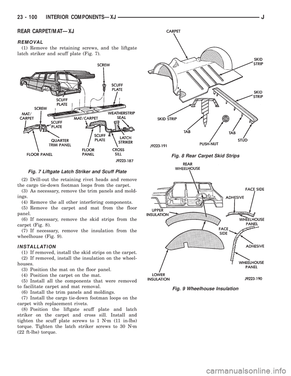
(1) Remove the retaining screws, and the liftgate
latch striker and scuff plate (Fig. 7).
(2) Drill-out the retaining rivet heads and remove
the cargo tie-down footman loops from the carpet.
(3) As necessary, remove the trim panels and mold-
ings.
(4) Remove the all other interfering components.
(5) Remove the carpet and mat from the floor
panel.
(6) If necessary, remove the skid strips from the
carpet (Fig. 8).
(7) If necessary, remove the insulation from the
wheelhouse (Fig. 9).
INSTALLATION
(1) If removed, install the skid strips on the carpet.
(2) If removed, install the insulation on the wheel-
houses.
(3) Position the mat on the floor panel.
(4) Position the carpet on the mat.
(5) Install all the components that were removed
to facilitate carpet and mat removal.
(6) Install the trim panels and moldings.
(7) Install the cargo tie-down footman loops on the
carpet with replacement rivets.
(8) Position the liftgate scuff plate and latch
striker on the carpet and cross sill. Install and
tighten the scuff plate screws to 1 Nzm (11 in-lbs)
torque. Tighten the latch striker screws to 30 Nzm
(22 ft-lbs) torque.
Fig. 7 Liftgate Latch Striker and Scuff Plate
Fig. 8 Rear Carpet Skid Strips
Fig. 9 Wheelhouse Insulation
23 - 100 INTERIOR COMPONENTSÐXJJ
Page 2022 of 2158
EXTERIOR COMPONENTS
INDEX
page page
Battery TrayÐYJ......................... 110
Body Side Step MoldingÐYJ................ 115
Body Stripes/DecalsÐYJ................... 116
Cowl Grille and ScreenÐYJ................ 109
Cowl Weatherstrip SealÐYJ................ 109
Exterior Nameplates (Adhesive-Backed)ÐYJ.... 120
External Spare/Wheel Tire CarrierÐYJ........ 133
Fender FlareÐYJ........................ 114
Fender Inner Splash ShieldsÐYJ............. 116
Fender Splash ApronsÐYJ................. 115
FendersÐYJ............................ 110
Fuel Filler Protector/NozzleÐYJ............. 121
Half Metal Door Mirror (External)ÐYJ......... 121
Hard Top Liftgate GlassÐYJ................ 124
Hard Top RepairÐYJ..................... 127
Hard Top Roof VentÐYJ................... 127
Hard TopÐYJ........................... 126Hood AlignmentÐYJ...................... 107
Hood Insulator PanelÐYJ.................. 107
Hood Safety LatchÐYJ.................... 109
HoodÐYJ.............................. 107
Liftgate Glass Weatherstrip Seal ReplacementÐYJ. 125
Radiator Grille AppliqueÐYJ................ 104
Soft Top Service InformationÐYJ............. 127
Soft Top ServiceÐYJ..................... 129
Sport BarÐYJ........................... 132
Tailgate AdjustmentÐYJ................... 121
Tailgate HingeÐYJ....................... 121
Tailgate Latch and Release HandleÐYJ........ 122
Tailgate Latch StrikerÐYJ.................. 123
Tailgate Lock CylinderÐYJ................. 122
Tailgate Weatherstrip SealÐYJ.............. 123
TailgateÐYJ............................ 121
Wheelhouse Splash LinersÐYJ.............. 115
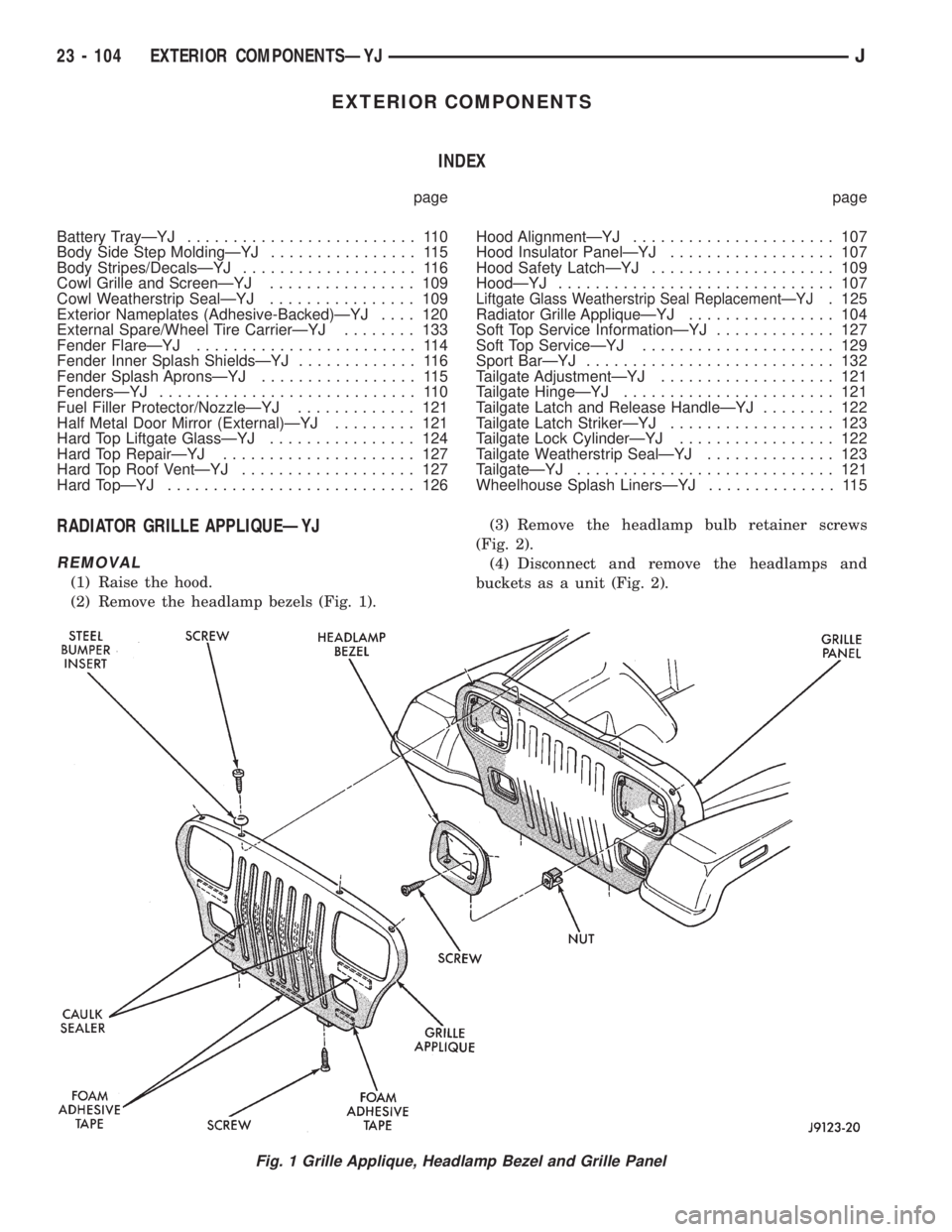
RADIATOR GRILLE APPLIQUEÐYJ
REMOVAL
(1) Raise the hood.
(2) Remove the headlamp bezels (Fig. 1).(3) Remove the headlamp bulb retainer screws
(Fig. 2).
(4) Disconnect and remove the headlamps and
buckets as a unit (Fig. 2).
Fig. 1 Grille Applique, Headlamp Bezel and Grille Panel
23 - 104 EXTERIOR COMPONENTSÐYJJ
Page 2032 of 2158
(8) Left fender:
²Install the air cleaner housing and support bracket
on the fender inner panel.
²Install the horn on the fender inner panel.
²Install the windshield washer fluid reservoir and
coolant reserve bottle on the fender inner panel.
(9) Right fender:
²Install the jack storage tray and A/C receiver/drier
on the fender inner panel.
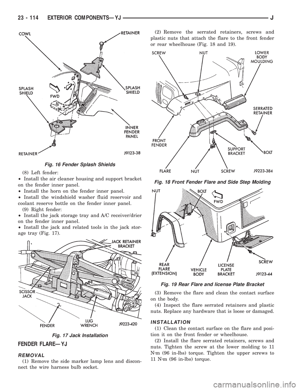
²Install the jack and related tools in the jack stor-
age tray (Fig. 17).
FENDER FLAREÐYJ
REMOVAL
(1) Remove the side marker lamp lens and discon-
nect the wire harness bulb socket.(2) Remove the serrated retainers, screws and
plastic nuts that attach the flare to the front fender
or rear wheelhouse (Fig. 18 and 19).
(3) Remove the flare and clean the contact surface
on the body.
(4) Inspect the flare serrated retainers and plastic
nuts. Replace any hardware that is loose or damaged.
INSTALLATION
(1) Clean the contact surface on the flare and posi-
tion it on the front fender or wheelhouse.
(2) Install the flare serrated retainers, screws and
nuts. Tighten the screw at the lower molding to 11
Nzm (96 in-lbs) torque. Tighten the upper screws to
11 Nzm (96 in-lbs) torque.
Fig. 16 Fender Splash Shields
Fig. 17 Jack Installation
Fig. 18 Front Fender Flare and Side Step Molding
Fig. 19 Rear Flare and license Plate Bracket
23 - 114 EXTERIOR COMPONENTSÐYJJ