1995 JEEP YJ fuel
[x] Cancel search: fuelPage 1996 of 2158
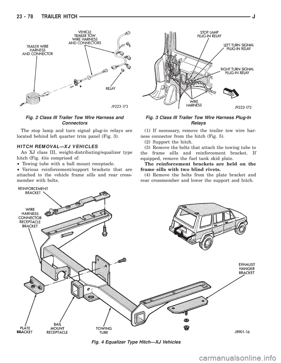
The stop lamp and turn signal plug-in relays are
located behind left quarter trim panel (Fig. 3).
HITCH REMOVALÐXJ VEHICLES
An XJ class III, weight-distributing/equalizer type
hitch (Fig. 4)is comprised of:
²Towing tube with a ball mount receptacle.
²Various reinforcement/support brackets that are
attached to the vehicle frame sills and rear cross-
member with bolts.(1) If necessary, remove the trailer tow wire har-
ness connector from the hitch (Fig. 5).
(2) Support the hitch.
(3) Remove the bolts that attach the towing tube to
the frame sills and reinforcement bracket. If
equipped, remove the fuel tank skid plate.
The reinforcement brackets are held on the
frame sills with two blind rivets.
(4) Remove the bolts from the plate bracket and
rear crossmember and lower the support and hitch.
Fig. 4 Equalizer Type HitchÐXJ Vehicles
Fig. 2 Class III Trailer Tow Wire Harness and
ConnectorsFig. 3 Class III Trailer Tow Wire Harness Plug-In
Relays
23 - 78 TRAILER HITCHJ
Page 1997 of 2158
INSTALLATIONÐXJ VEHICLES
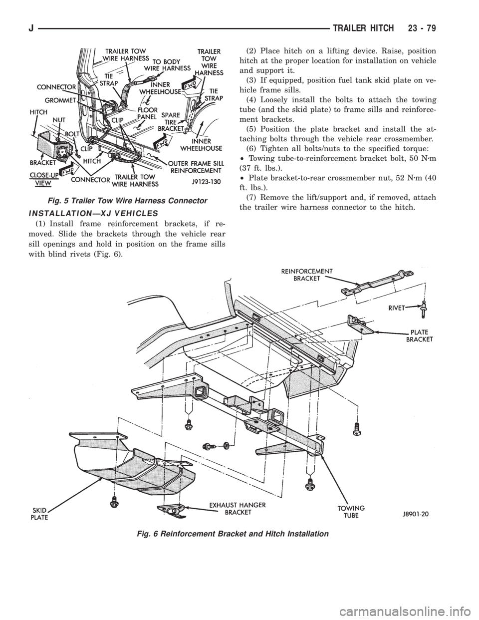
(1) Install frame reinforcement brackets, if re-
moved. Slide the brackets through the vehicle rear
sill openings and hold in position on the frame sills
with blind rivets (Fig. 6).(2) Place hitch on a lifting device. Raise, position
hitch at the proper location for installation on vehicle
and support it.
(3) If equipped, position fuel tank skid plate on ve-
hicle frame sills.
(4) Loosely install the bolts to attach the towing
tube (and the skid plate) to frame sills and reinforce-
ment brackets.
(5) Position the plate bracket and install the at-
taching bolts through the vehicle rear crossmember.
(6) Tighten all bolts/nuts to the specified torque:
²Towing tube-to-reinforcement bracket bolt, 50 Nzm
(37 ft. lbs.).
²Plate bracket-to-rear crossmember nut, 52 Nzm (40
ft. lbs.).
(7) Remove the lift/support and, if removed, attach
the trailer wire harness connector to the hitch.
Fig. 6 Reinforcement Bracket and Hitch Installation
Fig. 5 Trailer Tow Wire Harness Connector
JTRAILER HITCH 23 - 79
Page 2022 of 2158
EXTERIOR COMPONENTS
INDEX
page page
Battery TrayÐYJ......................... 110
Body Side Step MoldingÐYJ................ 115
Body Stripes/DecalsÐYJ................... 116
Cowl Grille and ScreenÐYJ................ 109
Cowl Weatherstrip SealÐYJ................ 109
Exterior Nameplates (Adhesive-Backed)ÐYJ.... 120
External Spare/Wheel Tire CarrierÐYJ........ 133
Fender FlareÐYJ........................ 114
Fender Inner Splash ShieldsÐYJ............. 116
Fender Splash ApronsÐYJ................. 115
FendersÐYJ............................ 110
Fuel Filler Protector/NozzleÐYJ............. 121
Half Metal Door Mirror (External)ÐYJ......... 121
Hard Top Liftgate GlassÐYJ................ 124
Hard Top RepairÐYJ..................... 127
Hard Top Roof VentÐYJ................... 127
Hard TopÐYJ........................... 126Hood AlignmentÐYJ...................... 107
Hood Insulator PanelÐYJ.................. 107
Hood Safety LatchÐYJ.................... 109
HoodÐYJ.............................. 107
Liftgate Glass Weatherstrip Seal ReplacementÐYJ. 125
Radiator Grille AppliqueÐYJ................ 104
Soft Top Service InformationÐYJ............. 127
Soft Top ServiceÐYJ..................... 129
Sport BarÐYJ........................... 132
Tailgate AdjustmentÐYJ................... 121
Tailgate HingeÐYJ....................... 121
Tailgate Latch and Release HandleÐYJ........ 122
Tailgate Latch StrikerÐYJ.................. 123
Tailgate Lock CylinderÐYJ................. 122
Tailgate Weatherstrip SealÐYJ.............. 123
TailgateÐYJ............................ 121
Wheelhouse Splash LinersÐYJ.............. 115
RADIATOR GRILLE APPLIQUEÐYJ
REMOVAL
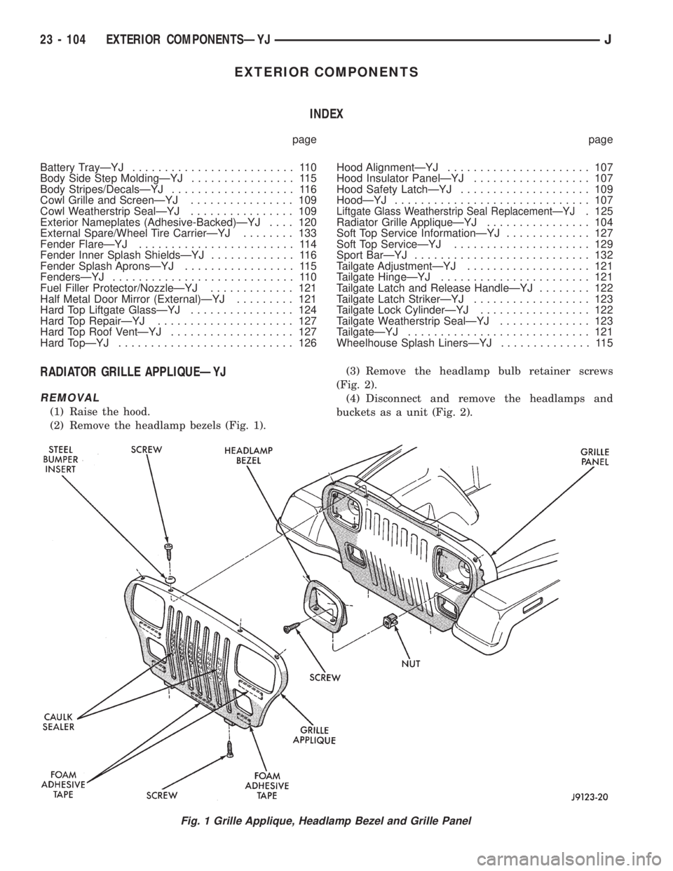
(1) Raise the hood.
(2) Remove the headlamp bezels (Fig. 1).(3) Remove the headlamp bulb retainer screws
(Fig. 2).
(4) Disconnect and remove the headlamps and
buckets as a unit (Fig. 2).
Fig. 1 Grille Applique, Headlamp Bezel and Grille Panel
23 - 104 EXTERIOR COMPONENTSÐYJJ
Page 2039 of 2158
(3) Position the replacement nameplate on the
panel and apply inward force to seat it.
FUEL FILLER PROTECTOR/NOZZLEÐYJ
REMOVAL
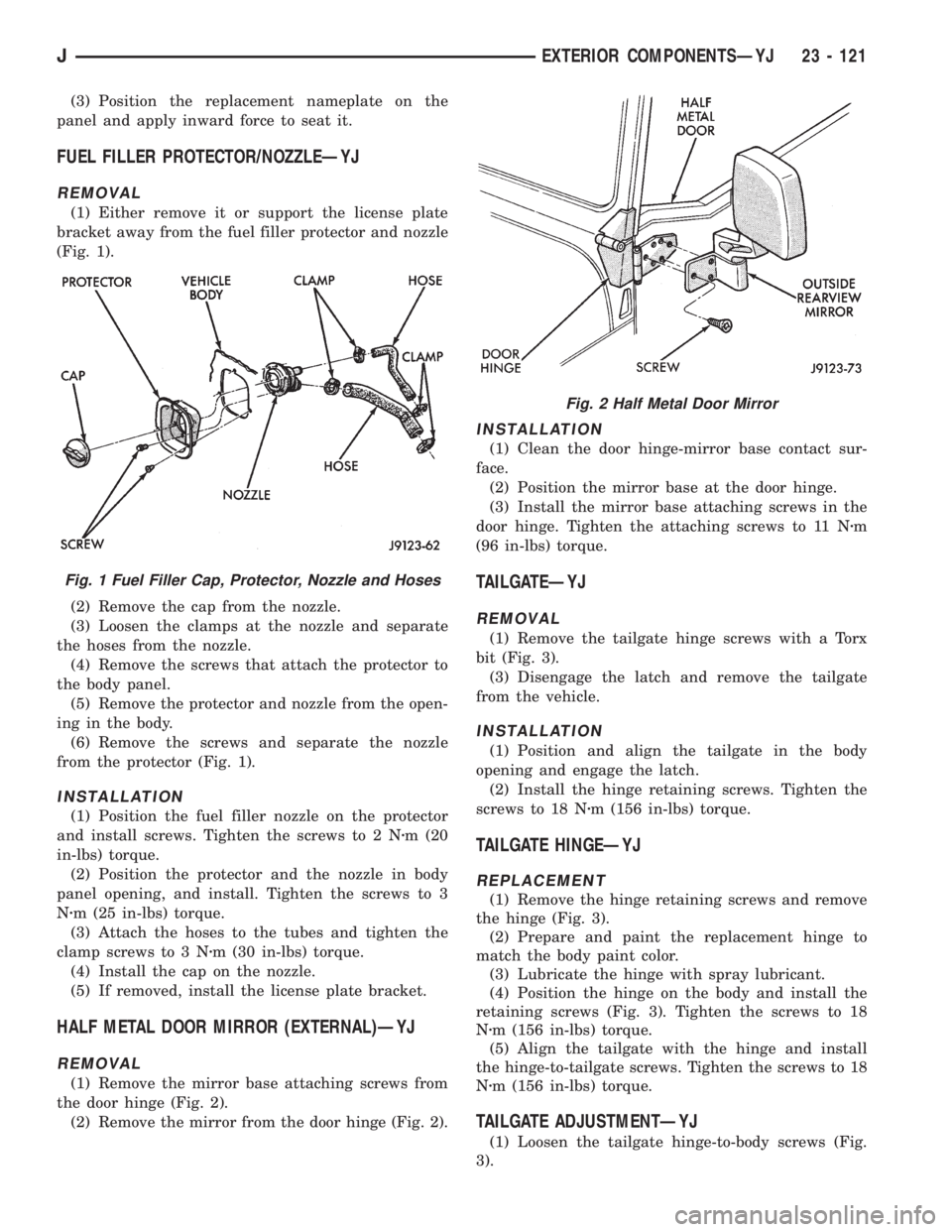
(1) Either remove it or support the license plate
bracket away from the fuel filler protector and nozzle
(Fig. 1).
(2) Remove the cap from the nozzle.
(3) Loosen the clamps at the nozzle and separate
the hoses from the nozzle.
(4) Remove the screws that attach the protector to
the body panel.
(5) Remove the protector and nozzle from the open-
ing in the body.
(6) Remove the screws and separate the nozzle
from the protector (Fig. 1).
INSTALLATION
(1) Position the fuel filler nozzle on the protector
and install screws. Tighten the screws to 2 Nzm (20
in-lbs) torque.
(2) Position the protector and the nozzle in body
panel opening, and install. Tighten the screws to 3
Nzm (25 in-lbs) torque.
(3) Attach the hoses to the tubes and tighten the
clamp screws to 3 Nzm (30 in-lbs) torque.
(4) Install the cap on the nozzle.
(5) If removed, install the license plate bracket.
HALF METAL DOOR MIRROR (EXTERNAL)ÐYJ
REMOVAL
(1) Remove the mirror base attaching screws from
the door hinge (Fig. 2).
(2) Remove the mirror from the door hinge (Fig. 2).
INSTALLATION
(1) Clean the door hinge-mirror base contact sur-
face.
(2) Position the mirror base at the door hinge.
(3) Install the mirror base attaching screws in the
door hinge. Tighten the attaching screws to 11 Nzm
(96 in-lbs) torque.
TAILGATEÐYJ
REMOVAL
(1) Remove the tailgate hinge screws with a Torx
bit (Fig. 3).
(3) Disengage the latch and remove the tailgate
from the vehicle.
INSTALLATION
(1) Position and align the tailgate in the body
opening and engage the latch.
(2) Install the hinge retaining screws. Tighten the
screws to 18 Nzm (156 in-lbs) torque.
TAILGATE HINGEÐYJ
REPLACEMENT
(1) Remove the hinge retaining screws and remove
the hinge (Fig. 3).
(2) Prepare and paint the replacement hinge to
match the body paint color.
(3) Lubricate the hinge with spray lubricant.
(4) Position the hinge on the body and install the
retaining screws (Fig. 3). Tighten the screws to 18
Nzm (156 in-lbs) torque.
(5) Align the tailgate with the hinge and install
the hinge-to-tailgate screws. Tighten the screws to 18
Nzm (156 in-lbs) torque.
TAILGATE ADJUSTMENTÐYJ
(1) Loosen the tailgate hinge-to-body screws (Fig.
3).
Fig. 1 Fuel Filler Cap, Protector, Nozzle and Hoses
Fig. 2 Half Metal Door Mirror
JEXTERIOR COMPONENTSÐYJ 23 - 121
Page 2108 of 2158
(4) Plug the harness into the low pressure switch
(Fig. 16).
(5) Connect the A/C hoses to the condenser.
(6) Connect the transmission cooler lines (if
equipped with automatic transmission).
(7) Connect the fan shroud and the radiator hoses.
(8) Fill coolant system (Refer to cooling for proper
procedure).
(9) Evacuate and charge the A/C system.
CONDENSERÐ4.0L ENGINES
REVIEW WARNINGS AND CAUTIONS IN
THIS GROUP BEFORE PERFORMING THIS
OPERATION.
REMOVAL
(1) Recover refrigerant from the system.
(2) Remove the upper radiator support.
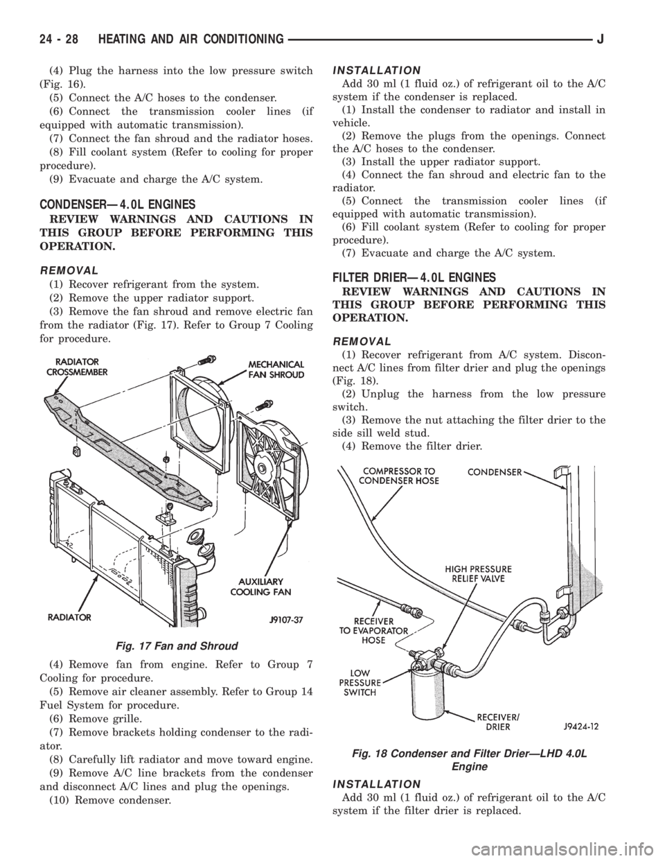
(3) Remove the fan shroud and remove electric fan
from the radiator (Fig. 17). Refer to Group 7 Cooling
for procedure.
(4) Remove fan from engine. Refer to Group 7
Cooling for procedure.
(5) Remove air cleaner assembly. Refer to Group 14
Fuel System for procedure.
(6) Remove grille.
(7) Remove brackets holding condenser to the radi-
ator.
(8) Carefully lift radiator and move toward engine.
(9) Remove A/C line brackets from the condenser
and disconnect A/C lines and plug the openings.
(10) Remove condenser.
INSTALLATION
Add 30 ml (1 fluid oz.) of refrigerant oil to the A/C
system if the condenser is replaced.
(1) Install the condenser to radiator and install in
vehicle.
(2) Remove the plugs from the openings. Connect
the A/C hoses to the condenser.
(3) Install the upper radiator support.
(4) Connect the fan shroud and electric fan to the
radiator.
(5) Connect the transmission cooler lines (if
equipped with automatic transmission).
(6) Fill coolant system (Refer to cooling for proper
procedure).
(7) Evacuate and charge the A/C system.
FILTER DRIERÐ4.0L ENGINES
REVIEW WARNINGS AND CAUTIONS IN
THIS GROUP BEFORE PERFORMING THIS
OPERATION.
REMOVAL
(1) Recover refrigerant from A/C system. Discon-
nect A/C lines from filter drier and plug the openings
(Fig. 18).
(2) Unplug the harness from the low pressure
switch.
(3) Remove the nut attaching the filter drier to the
side sill weld stud.
(4) Remove the filter drier.
INSTALLATION
Add 30 ml (1 fluid oz.) of refrigerant oil to the A/C
system if the filter drier is replaced.
Fig. 17 Fan and Shroud
Fig. 18 Condenser and Filter DrierÐLHD 4.0L
Engine
24 - 28 HEATING AND AIR CONDITIONINGJ
Page 2118 of 2158
EMISSION CONTROL SYSTEMS
CONTENTS
page page
COMPONENT REMOVAL/INSTALLATION....... 7
EMISSION CONTROLS.................... 4GENERAL INFORMATION.................. 1
GENERAL INFORMATION
INDEX
page page
Catalytic Convertor......................... 1
DRB Scan Tool............................ 2
Exhaust Gas Recirculation (EGR) System........ 1Service Reminder Indicator (SRI) Lamp.......... 1
Vacuum Hose Routing Schematics............. 2
Vehicle Emission Control Information (VECI) Label . 1
Throughout this group, references are made to par-
ticular vehicle models by alphabetical designation
(XJ or YJ) or by the particular vehicle nameplate. A
chart showing a breakdown of alphabetical designa-
tions is included in the Introduction section at the
beginning of this manual.
Information on the air cleaner housing and the air
cleaner element can be found in Group 14, Fuel Sys-
tems.
CATALYTIC CONVERTOR
Refer to Group 11, Exhaust System and Intake
Manifold for information.
EXHAUST GAS RECIRCULATION (EGR) SYSTEM
An EGR system is not used with the 2.5L 4 cylin-
der or the 4.0L 6 cylinder engine on any XJ or YJ
model.
SERVICE REMINDER INDICATOR (SRI) LAMP
The instrument panel mounted SRI lamp was for-
merly referred to as the emission maintenance re-
minder (EMR) lamp. It isnot usedon any XJ or YJ
model for the 1995 model year.
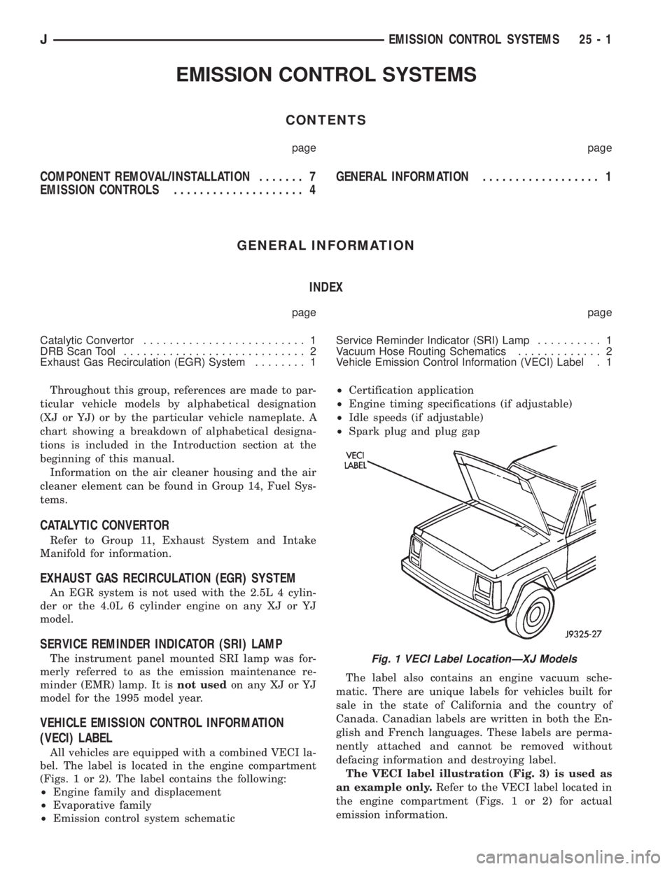
VEHICLE EMISSION CONTROL INFORMATION
(VECI) LABEL
All vehicles are equipped with a combined VECI la-
bel. The label is located in the engine compartment
(Figs. 1 or 2). The label contains the following:
²Engine family and displacement
²Evaporative family
²Emission control system schematic²Certification application
²Engine timing specifications (if adjustable)
²Idle speeds (if adjustable)
²Spark plug and plug gap
The label also contains an engine vacuum sche-
matic. There are unique labels for vehicles built for
sale in the state of California and the country of
Canada. Canadian labels are written in both the En-
glish and French languages. These labels are perma-
nently attached and cannot be removed without
defacing information and destroying label.
The VECI label illustration (Fig. 3) is used as
an example only.Refer to the VECI label located in
the engine compartment (Figs. 1 or 2) for actual
emission information.
Fig. 1 VECI Label LocationÐXJ Models
JEMISSION CONTROL SYSTEMS 25 - 1
Page 2121 of 2158
EMISSION CONTROLS
INDEX
page page
Crankcase Ventilation System................. 5
EVAP (Evaporation) Control System............ 4
EVAP Canister............................ 4Fuel Tank Filler Tube Cap.................... 4
Oxygen (O2S) Sensor....................... 6
Pressure Relief/Rollover Valve................. 6
EVAP (EVAPORATION) CONTROL SYSTEM
GENERAL INFORMATION
The function of the EVAP control system is to pre-
vent the emissions of gasoline vapors from the fuel
tank into the atmosphere. When fuel evaporates in
the fuel tank, the vapors pass through vent hoses or
tubes to a carbon filled EVAP canister. They are tem-
porarily held in the canister until they can be drawn
into the intake manifold when the engine is running.
The EVAP canister is a feature on all models for
the storage of fuel vapors from the fuel tank.
The hoses used in this system are specially
manufactured. If replacement becomes neces-
sary, it is important to use only fuel resistant
hose.
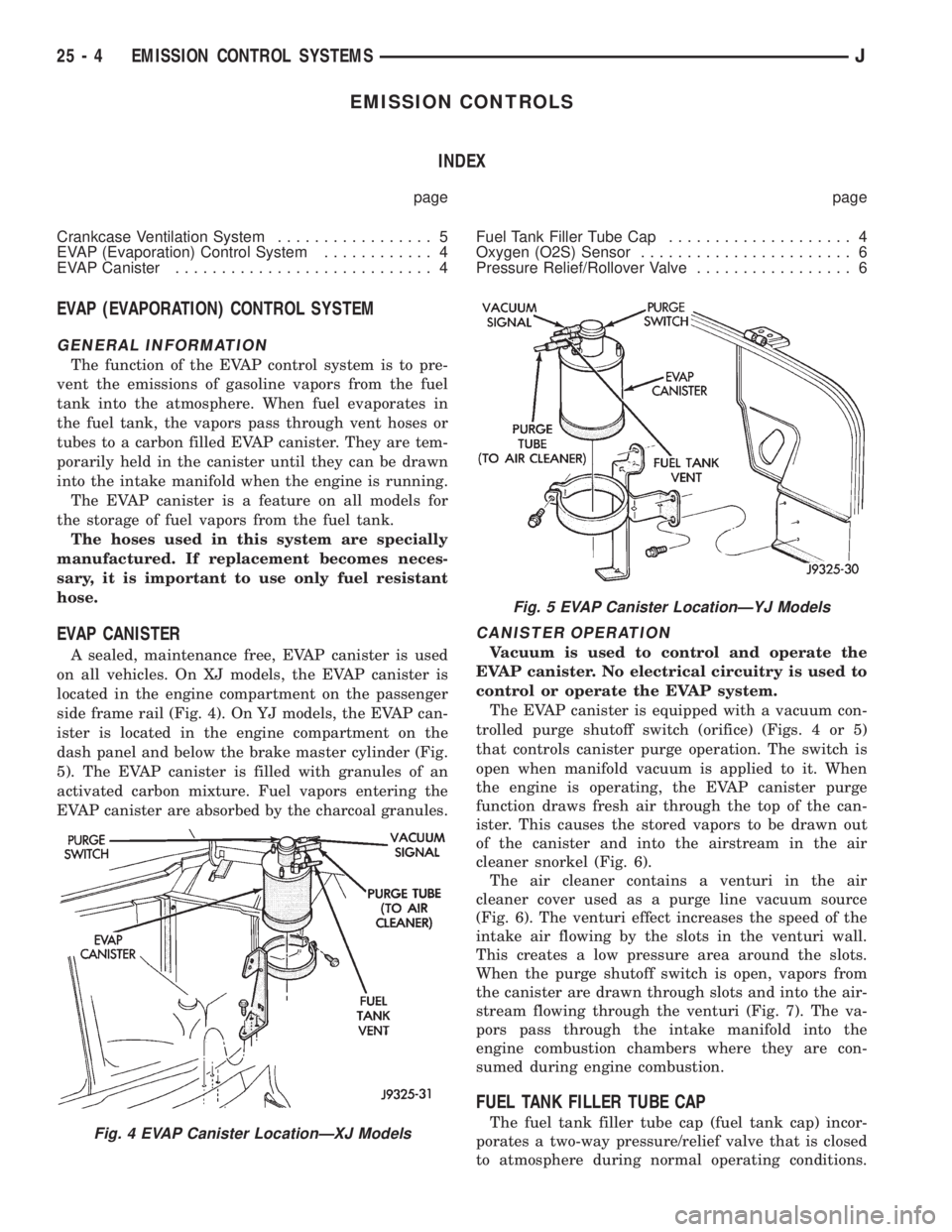
EVAP CANISTER
A sealed, maintenance free, EVAP canister is used
on all vehicles. On XJ models, the EVAP canister is
located in the engine compartment on the passenger
side frame rail (Fig. 4). On YJ models, the EVAP can-
ister is located in the engine compartment on the
dash panel and below the brake master cylinder (Fig.
5). The EVAP canister is filled with granules of an
activated carbon mixture. Fuel vapors entering the
EVAP canister are absorbed by the charcoal granules.
CANISTER OPERATION
Vacuum is used to control and operate the
EVAP canister. No electrical circuitry is used to
control or operate the EVAP system.
The EVAP canister is equipped with a vacuum con-
trolled purge shutoff switch (orifice) (Figs. 4 or 5)
that controls canister purge operation. The switch is
open when manifold vacuum is applied to it. When
the engine is operating, the EVAP canister purge
function draws fresh air through the top of the can-
ister. This causes the stored vapors to be drawn out
of the canister and into the airstream in the air
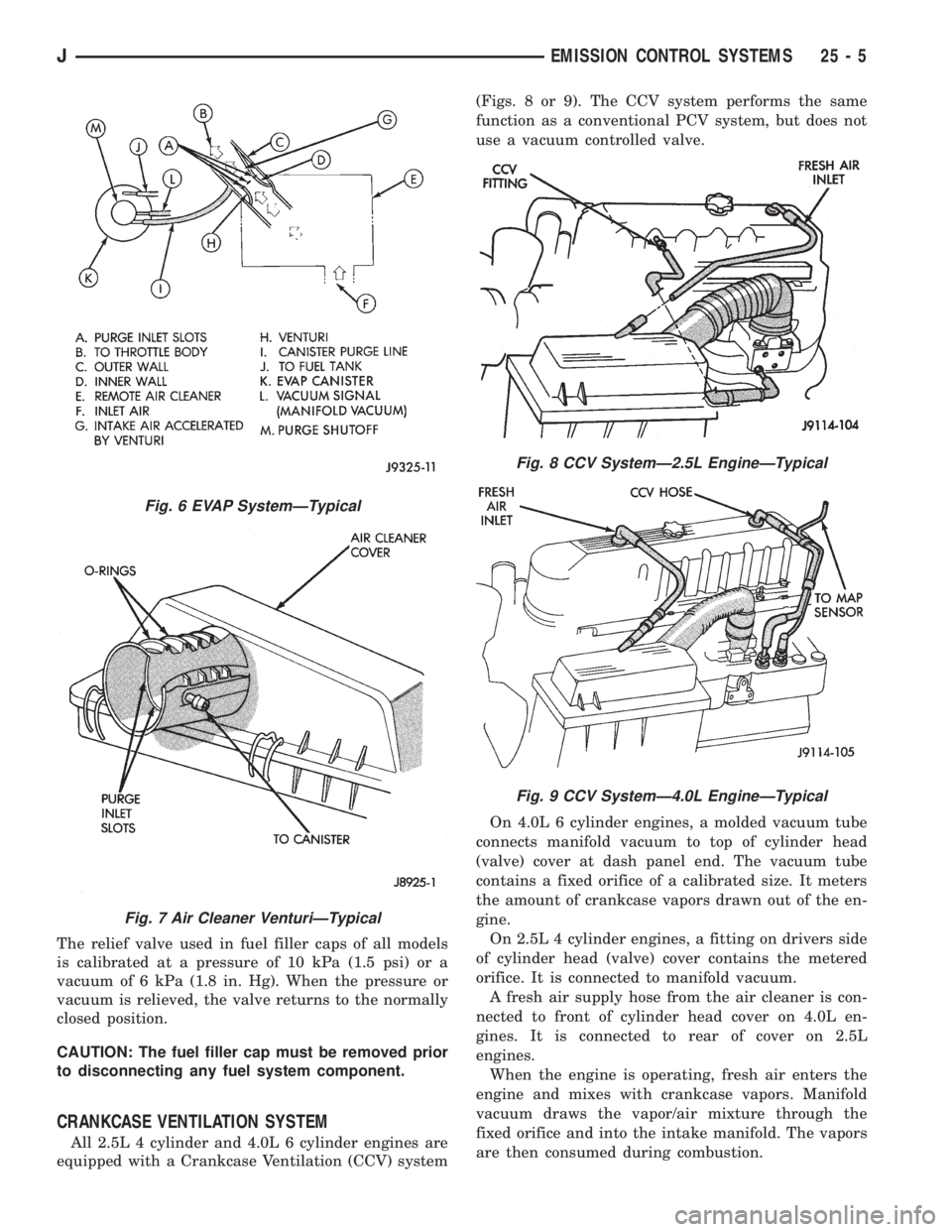
cleaner snorkel (Fig. 6).
The air cleaner contains a venturi in the air
cleaner cover used as a purge line vacuum source
(Fig. 6). The venturi effect increases the speed of the
intake air flowing by the slots in the venturi wall.
This creates a low pressure area around the slots.
When the purge shutoff switch is open, vapors from
the canister are drawn through slots and into the air-
stream flowing through the venturi (Fig. 7). The va-
pors pass through the intake manifold into the
engine combustion chambers where they are con-
sumed during engine combustion.
FUEL TANK FILLER TUBE CAP
The fuel tank filler tube cap (fuel tank cap) incor-
porates a two-way pressure/relief valve that is closed
to atmosphere during normal operating conditions.Fig. 4 EVAP Canister LocationÐXJ Models
Fig. 5 EVAP Canister LocationÐYJ Models
25 - 4 EMISSION CONTROL SYSTEMSJ
Page 2122 of 2158
The relief valve used in fuel filler caps of all models
is calibrated at a pressure of 10 kPa (1.5 psi) or a
vacuum of 6 kPa (1.8 in. Hg). When the pressure or
vacuum is relieved, the valve returns to the normally
closed position.
CAUTION: The fuel filler cap must be removed prior
to disconnecting any fuel system component.
CRANKCASE VENTILATION SYSTEM
All 2.5L 4 cylinder and 4.0L 6 cylinder engines are
equipped with a Crankcase Ventilation (CCV) system(Figs. 8 or 9). The CCV system performs the same
function as a conventional PCV system, but does not
use a vacuum controlled valve.
On 4.0L 6 cylinder engines, a molded vacuum tube
connects manifold vacuum to top of cylinder head
(valve) cover at dash panel end. The vacuum tube
contains a fixed orifice of a calibrated size. It meters
the amount of crankcase vapors drawn out of the en-
gine.
On 2.5L 4 cylinder engines, a fitting on drivers side
of cylinder head (valve) cover contains the metered
orifice. It is connected to manifold vacuum.
A fresh air supply hose from the air cleaner is con-
nected to front of cylinder head cover on 4.0L en-
gines. It is connected to rear of cover on 2.5L
engines.
When the engine is operating, fresh air enters the
engine and mixes with crankcase vapors. Manifold
vacuum draws the vapor/air mixture through the
fixed orifice and into the intake manifold. The vapors
are then consumed during combustion.
Fig. 6 EVAP SystemÐTypical
Fig. 7 Air Cleaner VenturiÐTypical
Fig. 8 CCV SystemÐ2.5L EngineÐTypical
Fig. 9 CCV SystemÐ4.0L EngineÐTypical
JEMISSION CONTROL SYSTEMS 25 - 5