1995 JEEP YJ fuel
[x] Cancel search: fuelPage 1467 of 2158
INSTALLATION
(1) Install throttle body and new gasket. Tighten
throttle body mounting bolts to 12 Nzm (9 ft. lbs.)
torque.
(2) Connect idle air control motor and throttle po-
sition sensor wire connectors.
(3) Connect throttle linkage to throttle arm.
CAUTION: When the automatic transmission throttle
cable is connected, it MUST be adjusted.
(4) If equipped with an automatic transmission,
connect and adjust the transmission line pressure ca-
ble. Refer to Group 21, Transmissions for adjustment
procedure.
(5) Install air cleaner hose to throttle body.
(6) Connect negative battery cable to battery.
THROTTLE POSITION SENSOR (TPS)
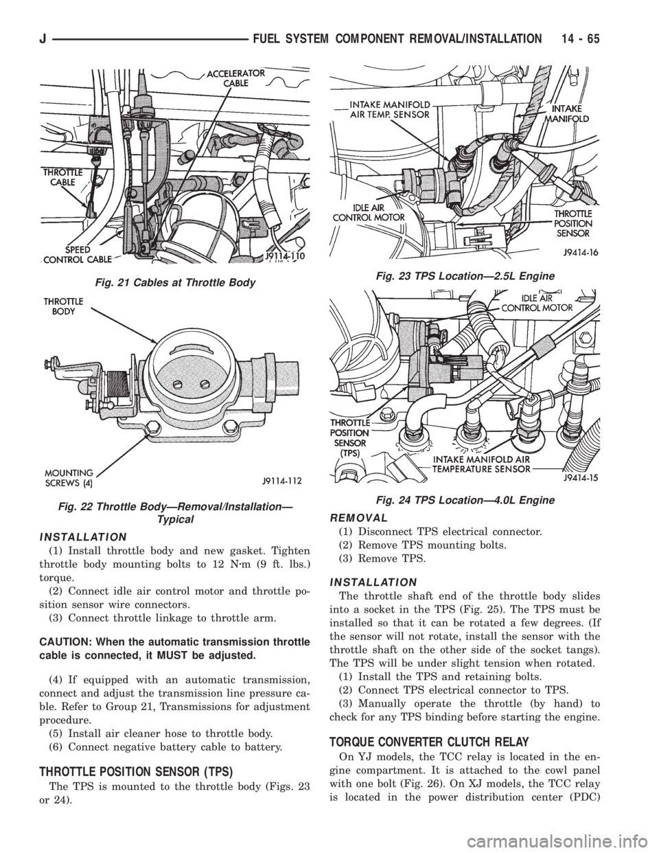
The TPS is mounted to the throttle body (Figs. 23
or 24).
REMOVAL
(1) Disconnect TPS electrical connector.
(2) Remove TPS mounting bolts.
(3) Remove TPS.
INSTALLATION
The throttle shaft end of the throttle body slides
into a socket in the TPS (Fig. 25). The TPS must be
installed so that it can be rotated a few degrees. (If
the sensor will not rotate, install the sensor with the
throttle shaft on the other side of the socket tangs).
The TPS will be under slight tension when rotated.
(1) Install the TPS and retaining bolts.
(2) Connect TPS electrical connector to TPS.
(3) Manually operate the throttle (by hand) to
check for any TPS binding before starting the engine.
TORQUE CONVERTER CLUTCH RELAY
On YJ models, the TCC relay is located in the en-
gine compartment. It is attached to the cowl panel
with one bolt (Fig. 26). On XJ models, the TCC relay
is located in the power distribution center (PDC)
Fig. 21 Cables at Throttle Body
Fig. 22 Throttle BodyÐRemoval/InstallationÐ
Typical
Fig. 23 TPS LocationÐ2.5L Engine
Fig. 24 TPS LocationÐ4.0L Engine
JFUEL SYSTEM COMPONENT REMOVAL/INSTALLATION 14 - 65
Page 1468 of 2158
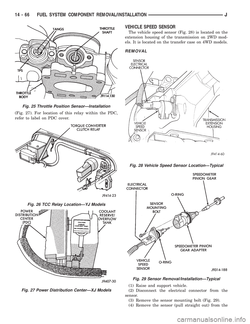
(Fig. 27). For location of this relay within the PDC,
refer to label on PDC cover.
VEHICLE SPEED SENSOR
The vehicle speed sensor (Fig. 28) is located on the
extension housing of the transmission on 2WD mod-
els. It is located on the transfer case on 4WD models.
REMOVAL
(1) Raise and support vehicle.
(2) Disconnect the electrical connector from the
sensor.
(3) Remove the sensor mounting bolt (Fig. 29).
(4) Remove the sensor (pull straight out) from the
Fig. 25 Throttle Position SensorÐInstallation
Fig. 26 TCC Relay LocationÐYJ Models
Fig. 27 Power Distribution CenterÐXJ Models
Fig. 28 Vehicle Speed Sensor LocationÐTypical
Fig. 29 Sensor Removal/InstallationÐTypical
14 - 66 FUEL SYSTEM COMPONENT REMOVAL/INSTALLATIONJ
Page 1469 of 2158
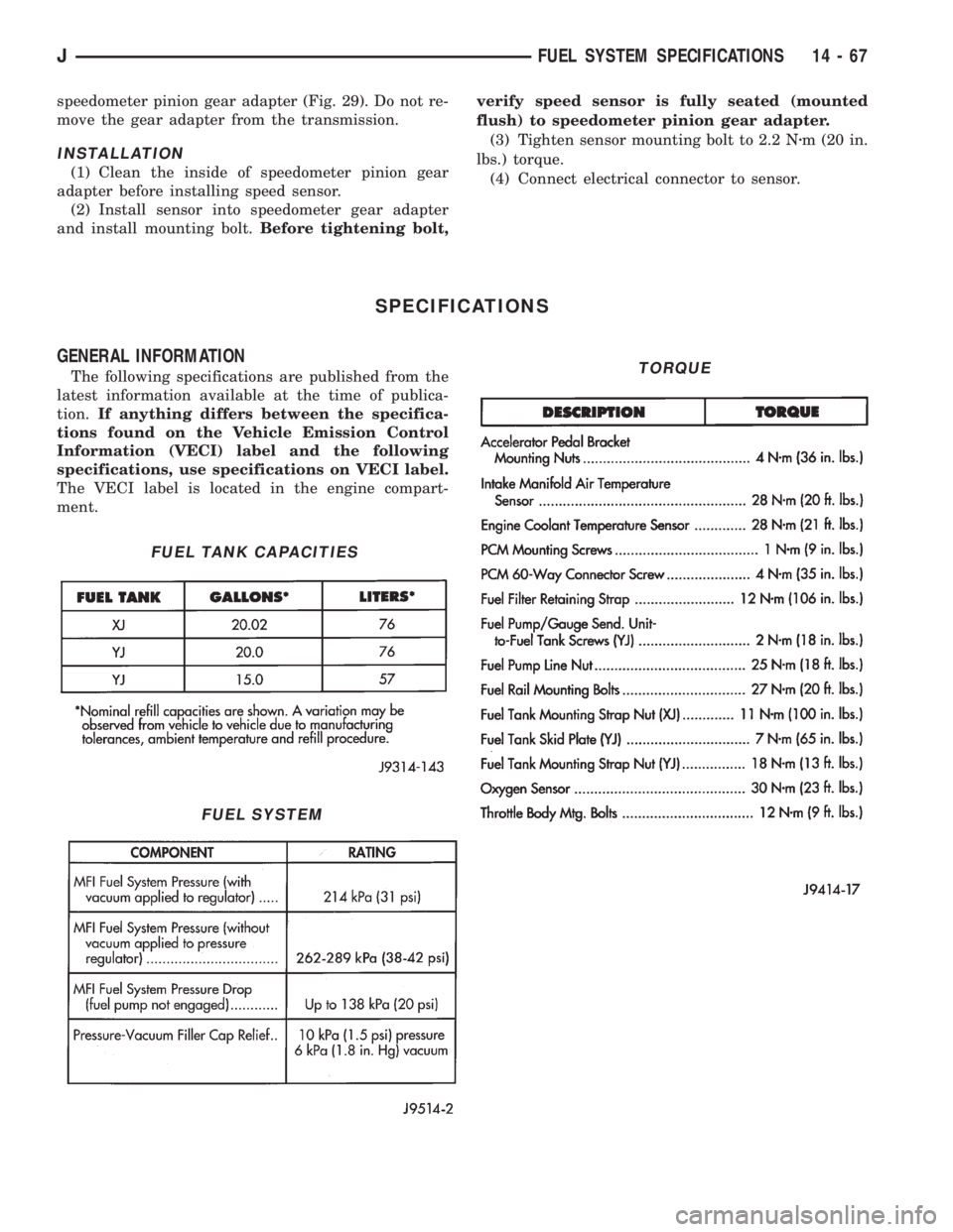
speedometer pinion gear adapter (Fig. 29). Do not re-
move the gear adapter from the transmission.
INSTALLATION
(1) Clean the inside of speedometer pinion gear
adapter before installing speed sensor.
(2) Install sensor into speedometer gear adapter
and install mounting bolt.Before tightening bolt,verify speed sensor is fully seated (mounted
flush) to speedometer pinion gear adapter.
(3) Tighten sensor mounting bolt to 2.2 Nzm (20 in.
lbs.) torque.
(4) Connect electrical connector to sensor.
SPECIFICATIONS
GENERAL INFORMATION
The following specifications are published from the
latest information available at the time of publica-
tion.If anything differs between the specifica-
tions found on the Vehicle Emission Control
Information (VECI) label and the following
specifications, use specifications on VECI label.
The VECI label is located in the engine compart-
ment.
FUEL TANK CAPACITIES
FUEL SYSTEM
TORQUE
JFUEL SYSTEM SPECIFICATIONS 14 - 67
Page 1540 of 2158
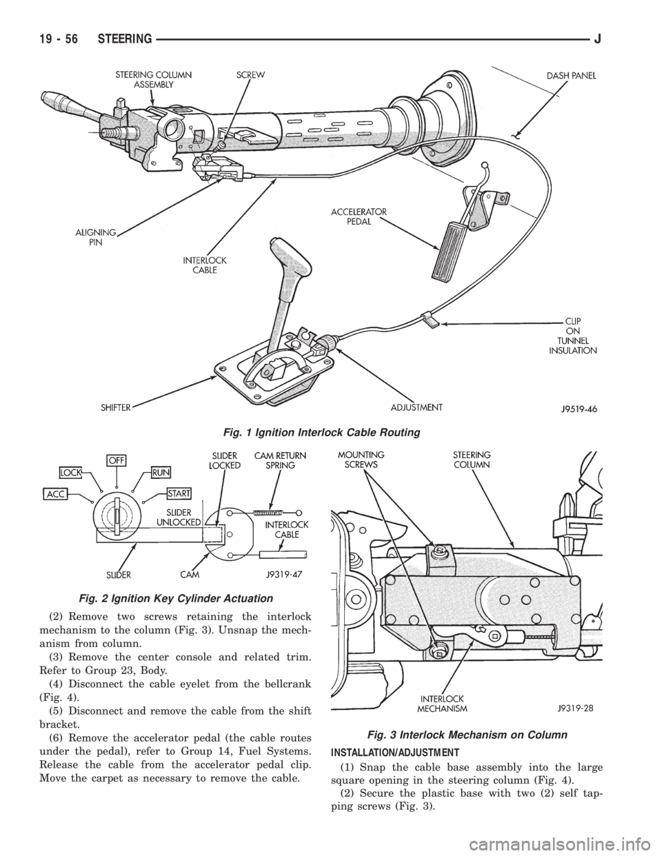
(2) Remove two screws retaining the interlock
mechanism to the column (Fig. 3). Unsnap the mech-
anism from column.
(3) Remove the center console and related trim.
Refer to Group 23, Body.
(4) Disconnect the cable eyelet from the bellcrank
(Fig. 4).
(5) Disconnect and remove the cable from the shift
bracket.
(6) Remove the accelerator pedal (the cable routes
under the pedal), refer to Group 14, Fuel Systems.
Release the cable from the accelerator pedal clip.
Move the carpet as necessary to remove the cable.INSTALLATION/ADJUSTMENT
(1) Snap the cable base assembly into the large
square opening in the steering column (Fig. 4).
(2) Secure the plastic base with two (2) self tap-
ping screws (Fig. 3).
Fig. 1 Ignition Interlock Cable Routing
Fig. 2 Ignition Key Cylinder Actuation
Fig. 3 Interlock Mechanism on Column
19 - 56 STEERINGJ
Page 1908 of 2158
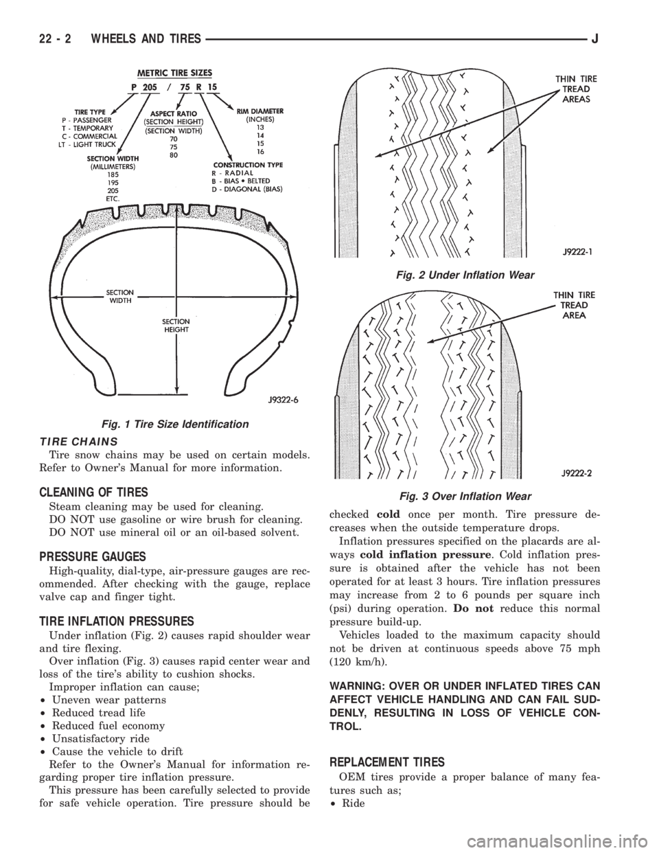
TIRE CHAINS
Tire snow chains may be used on certain models.
Refer to Owner's Manual for more information.
CLEANING OF TIRES
Steam cleaning may be used for cleaning.
DO NOT use gasoline or wire brush for cleaning.
DO NOT use mineral oil or an oil-based solvent.
PRESSURE GAUGES
High-quality, dial-type, air-pressure gauges are rec-
ommended. After checking with the gauge, replace
valve cap and finger tight.
TIRE INFLATION PRESSURES
Under inflation (Fig. 2) causes rapid shoulder wear
and tire flexing.
Over inflation (Fig. 3) causes rapid center wear and
loss of the tire's ability to cushion shocks.
Improper inflation can cause;
²Uneven wear patterns
²Reduced tread life
²Reduced fuel economy
²Unsatisfactory ride
²Cause the vehicle to drift
Refer to the Owner's Manual for information re-
garding proper tire inflation pressure.
This pressure has been carefully selected to provide
for safe vehicle operation. Tire pressure should becheckedcoldonce per month. Tire pressure de-
creases when the outside temperature drops.
Inflation pressures specified on the placards are al-
wayscold inflation pressure. Cold inflation pres-
sure is obtained after the vehicle has not been
operated for at least 3 hours. Tire inflation pressures
may increase from 2 to 6 pounds per square inch
(psi) during operation.Do notreduce this normal
pressure build-up.
Vehicles loaded to the maximum capacity should
not be driven at continuous speeds above 75 mph
(120 km/h).
WARNING: OVER OR UNDER INFLATED TIRES CAN
AFFECT VEHICLE HANDLING AND CAN FAIL SUD-
DENLY, RESULTING IN LOSS OF VEHICLE CON-
TROL.
REPLACEMENT TIRES
OEM tires provide a proper balance of many fea-
tures such as;
²Ride
Fig. 1 Tire Size Identification
Fig. 2 Under Inflation Wear
Fig. 3 Over Inflation Wear
22 - 2 WHEELS AND TIRESJ
Page 1921 of 2158
EXTERIOR COMPONENTS
INDEX
page page
Air Exhaust GrilleÐXJ...................... 25
Battery TrayÐXJ.......................... 14
Body Side Molding/CladdingÐXJ.............. 20
Body Stripes/DecalsÐXJ.................... 21
Brush GuardÐXJ.......................... 3
Cowl Grille and ScreenÐXJ................. 12
Cowl Weatherstrip Seal/Crossmember Air
DeflectorÐXJ........................... 11
Dash Panel Insulator PanelÐXJ.............. 12
Drip Rail MoldingÐXJ...................... 25
Exterior NameplatesÐXJ................... 26
External MirrorsÐXJ....................... 27
Front FenderÐXJ......................... 14
Fuel Filler Door BumpersÐXJ................ 27Fuel Filler Nozzle/TubeÐXJ................. 26
Grille and Grille Opening Panel (GOP)ÐXJ....... 3
Hood AdjustmentÐXJ...................... 10
Hood Hinge ReplacementÐXJ............... 10
Hood Latch ReplacementÐXJ................ 11
Hood Latch Striker ReplacementÐXJ.......... 11
HoodÐXJ................................ 7
Latch Release Cable ReplacementÐXJ......... 11
Luggage RackÐXJ........................ 28
Quarter Window AppliqueÐXJ................ 25
Radiator Support CrossmemberÐXJ............ 6
Rear Wheelhouse Flares and LinersÐXJ........ 19
Safety Latch Striker ReplacementÐXJ.......... 11
BRUSH GUARDÐXJ
REMOVAL
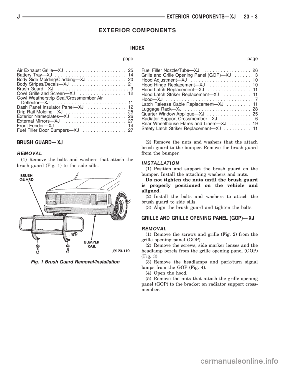
(1) Remove the bolts and washers that attach the
brush guard (Fig. 1) to the side sills.(2) Remove the nuts and washers that the attach
brush guard to the bumper. Remove the brush guard
from the bumper.INSTALLATION
(1) Position and support the brush guard on the
bumper. Install the attaching washers and nuts.
Do not tighten the nuts until the brush guard
is properly positioned on the vehicle and
aligned.
(2) Install the bolts and washers to attach the
brush guard to side sills.
(3) Align the brush guard and tighten the bolts.
GRILLE AND GRILLE OPENING PANEL (GOP)ÐXJ
REMOVAL
(1) Remove the screws and grille (Fig. 2) from the
grille opening panel (GOP).
(2) Remove the screws, side marker lenses and the
headlamp bezels from the grille opening panel (GOP)
(Fig. 3).
(3) Remove the headlamps and park/turn signal
lamps from the GOP (Fig. 4).
(4) Open the hood.
(5) Remove the nuts that attach the grille opening
panel (GOP) to the bracket on radiator support cross-
member.
Fig. 1 Brush Guard Removal/Installation
JEXTERIOR COMPONENTSÐXJ 23 - 3
Page 1944 of 2158
(3) Pull downward and remove the grille from ex-
haust port in the door opening panel.
INSTALLATION
(1) Position the slot located in the upper end of re-
placement grille at the exhaust port and insert edge
in the slot.
(2) Push inward and seat the grille in the exhaust
port.
(3) Install the screw to attach the grille to the door
opening panel.
EXTERIOR NAMEPLATESÐXJ
SERVICE INFORMATION
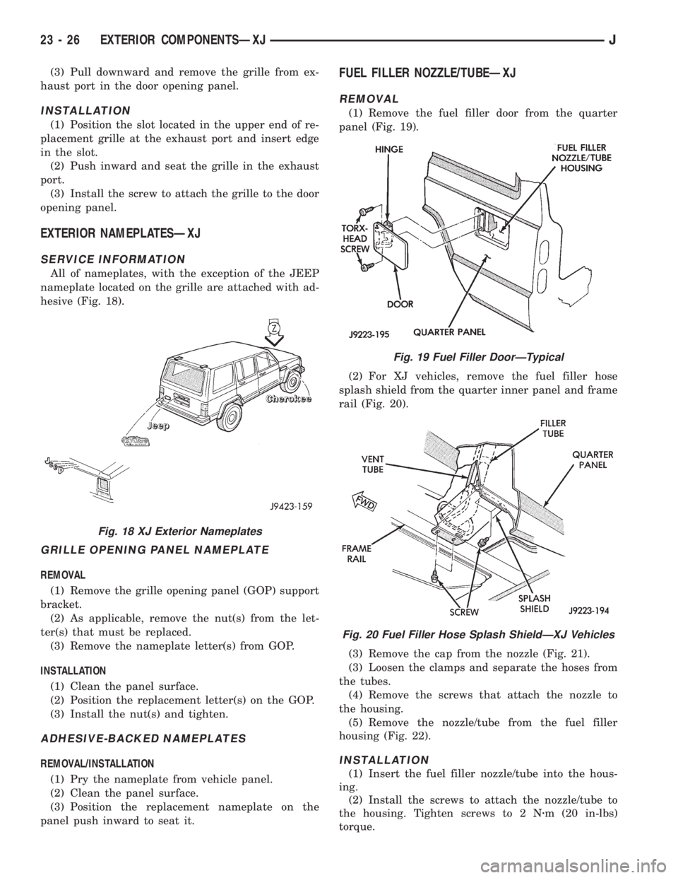
All of nameplates, with the exception of the JEEP
nameplate located on the grille are attached with ad-
hesive (Fig. 18).
GRILLE OPENING PANEL NAMEPLATE
REMOVAL
(1) Remove the grille opening panel (GOP) support
bracket.
(2) As applicable, remove the nut(s) from the let-
ter(s) that must be replaced.
(3) Remove the nameplate letter(s) from GOP.
INSTALLATION
(1) Clean the panel surface.
(2) Position the replacement letter(s) on the GOP.
(3) Install the nut(s) and tighten.
ADHESIVE-BACKED NAMEPLATES
REMOVAL/INSTALLATION
(1) Pry the nameplate from vehicle panel.
(2) Clean the panel surface.
(3) Position the replacement nameplate on the
panel push inward to seat it.
FUEL FILLER NOZZLE/TUBEÐXJ
REMOVAL
(1) Remove the fuel filler door from the quarter
panel (Fig. 19).
(2) For XJ vehicles, remove the fuel filler hose
splash shield from the quarter inner panel and frame
rail (Fig. 20).
(3) Remove the cap from the nozzle (Fig. 21).
(3) Loosen the clamps and separate the hoses from
the tubes.
(4) Remove the screws that attach the nozzle to
the housing.
(5) Remove the nozzle/tube from the fuel filler
housing (Fig. 22).
INSTALLATION
(1) Insert the fuel filler nozzle/tube into the hous-
ing.
(2) Install the screws to attach the nozzle/tube to
the housing. Tighten screws to 2 Nzm (20 in-lbs)
torque.
Fig. 18 XJ Exterior Nameplates
Fig. 19 Fuel Filler DoorÐTypical
Fig. 20 Fuel Filler Hose Splash ShieldÐXJ Vehicles
23 - 26 EXTERIOR COMPONENTSÐXJJ
Page 1945 of 2158
(3) Attach the hoses to the tubes with clamps.
Tighten the clamp screws to 4 Nzm (35 in-lbs) torque.
(4) Install the cap on nozzle.
(5) Install the fuel filler hose splash shield on the
quarter inner panel and frame rail.
(6) Install the fuel filler door on the quarter panel.
FUEL FILLER DOOR BUMPERSÐXJ
REPLACEMENT
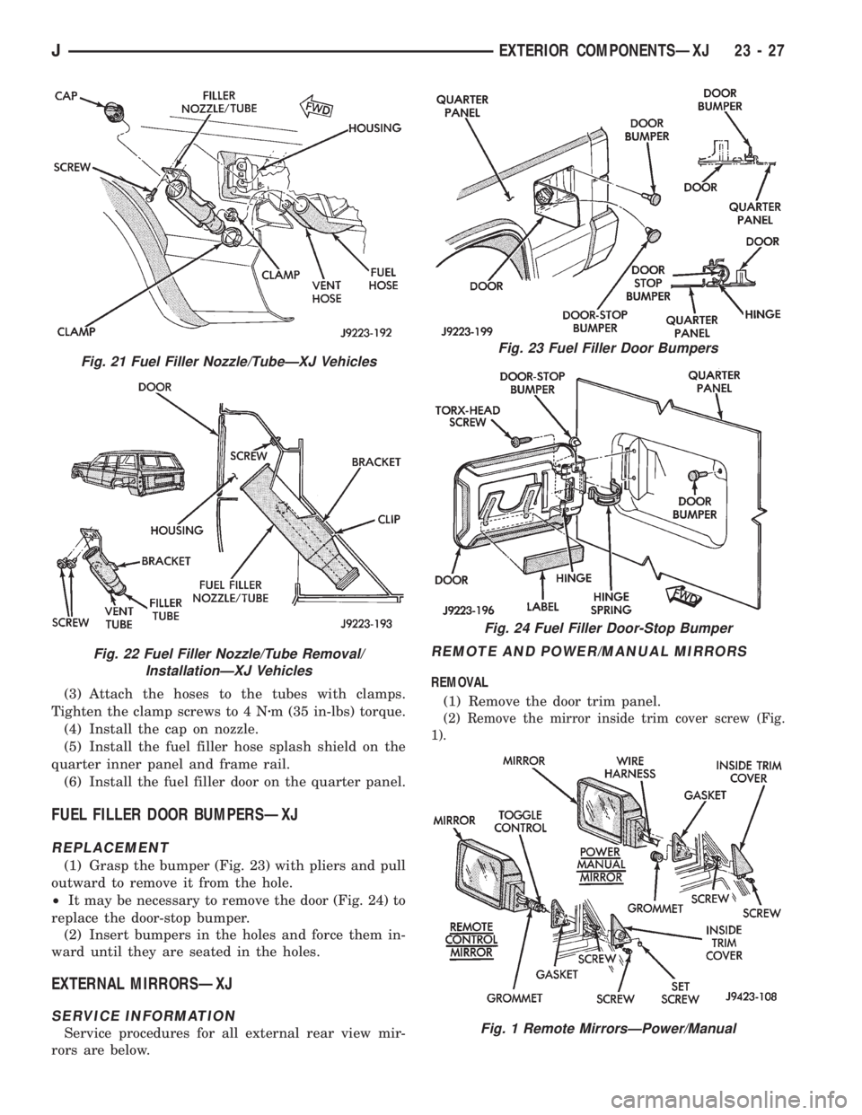
(1) Grasp the bumper (Fig. 23) with pliers and pull
outward to remove it from the hole.
²It may be necessary to remove the door (Fig. 24) to
replace the door-stop bumper.
(2) Insert bumpers in the holes and force them in-
ward until they are seated in the holes.
EXTERNAL MIRRORSÐXJ
SERVICE INFORMATION
Service procedures for all external rear view mir-
rors are below.
REMOTE AND POWER/MANUAL MIRRORS
REMOVAL
(1) Remove the door trim panel.
(2) Remove the mirror inside trim cover screw (Fig.
1).
Fig. 21 Fuel Filler Nozzle/TubeÐXJ Vehicles
Fig. 22 Fuel Filler Nozzle/Tube Removal/
InstallationÐXJ Vehicles
Fig. 23 Fuel Filler Door Bumpers
Fig. 24 Fuel Filler Door-Stop Bumper
Fig. 1 Remote MirrorsÐPower/Manual
JEXTERIOR COMPONENTSÐXJ 23 - 27