1995 JEEP YJ fog light
[x] Cancel search: fog lightPage 643 of 2158

INTERIOR LIGHTING
INDEX
page page
Cargo Lamp, Courtesy Lamps and Dome Lamp.... 1
Chime/Buzzer Module....................... 2
Diagram Index............................ 2
General Information........................ 1
Glove Box Lamp........................... 1
Ignition Switch Lamp........................ 1Instrument Panel Illumination Lamps............ 1
Reading Lamps........................... 2
Time Delay Relay.......................... 1
Underhood Lamp.......................... 2
Visor Vanity Mirror Lamps.................... 2
GENERAL INFORMATION
Circuit M1 supplies power to the glove box lamp,
left courtesy lamp, right courtesy lamp, dome lamp,
and cargo lamp. The M1 circuit also connects to the
remote keyless entry module. Circuit M1 is protected
by the ignition off draw (IOD) fuse (fuse 9) in the fuse
block.
Circuit E2 supplies power for the instrument panel
illumination lamps.
INSTRUMENT PANEL ILLUMINATION LAMPS
Circuit E2 from the headlamp switch splices to
supply power to the following illumination lamps:
²Ash receiver lamp
²Cigar lighter lamp
²Transmission range indicator lamp
²Transfer case range indicator lamp
²A/C-Heater switch lamp
²Heated rear window lamp
²Rear wiper switch lamp
²Fog lamp switch lamp
Fuse 19 in the fuse block protects circuit E2. Circuit
Z1 provides ground for all of the illumination lamps
except for the cigar lighter lamp. The cigar lighter
lamp is case grounded.
HELPFUL INFORMATION
Circuit E2 also supplies power to the radio, LCD
relay and the illumination lamps in the instrument
cluster.
IGNITION SWITCH LAMP
The time delay relay is used to allow a time-ON
function for the ignition switch lamp and the courtesy
lamp. Power for the relay is received on the M1
circuit from the IOD fuse (fuse F9) in the fuse block.
Circuit M2 provides ground for the time delay relay
through the right and left door ajar switches and the
headlamp switch. When a door is opened, or the
headlamp switch is moved to the dome lamp position,a ground path is provided for the relay on circuit M2.
This energizes the relay, causing the contacts to close.
When the relay contacts close, power is provided
through the relay to circuit M50. The M50 circuit
supplies current to the ignition switch lamp. Circuit
Z1 provides ground for the lamp.
GLOVE BOX LAMP
Circuit M1 from the IOD fuse (fuse F9) in the fuse
block powers the glove box lamp. A case grounded
switch, in series after the lamp, closes when the glove
box door is opened. The switch completes a path to
ground on circuit Z1.
CARGO LAMP, COURTESY LAMPS AND DOME
LAMP
Circuit M1 from the IOD fuse (fuse F9) in the fuse
block supplies power to the cargo, courtesy lamps and
dome lamp. This circuit is HOT at all times. The
ground path for the lamp is provided in three differ-
ent ways.
One way is through the door jamb switches. Circuit
M2 connects to the door jamb switches from the cour-
tesy and dome lamps. The switches are connected to
ground circuit Z1. When a door is opened, the plunger
in the switch closes, completing a path to ground.
The second way is through the liftgate switch. Cir-
cuit M2 connects to circuit M4 at the cargo lamp.
Circuit M4 connects to the liftgate switch. The lift-
gate switch connects to ground circuit Z1. When the
lift gate opens, the plunger in the switch closes, com-
pleting a path to ground.
The third ground path is through the headlamp
switch. Circuit M2 is spliced in with the headlamp
switch. When the operator turns the headlamp switch
to the dome lamp ON position, a ground path is
provided through the switch.
J8W-44 INTERIOR LIGHTINGÐXJ VEHICLES 8W - 44 - 1
Page 668 of 2158
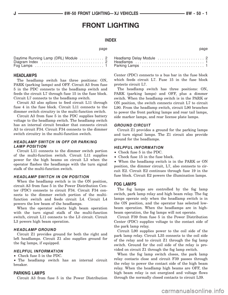
FRONT LIGHTING
INDEX
page page
Daytime Running Lamp (DRL) Module........... 2
Diagram Index............................ 2
Fog Lamps............................... 1Headlamp Delay Module..................... 2
Headlamps............................... 1
Parking Lamps............................ 1
HEADLAMPS
The headlamp switch has three positions: ON,
PARK (parking lamps) and OFF. Circuit A3 from fuse
5 in the PDC connects to the headlamp switch and
feeds the circuit L7 through fuse 15 in the fuse block.
Circuit L7 connects to the headlamp switch.
Circuit A3 also splices to feed circuit L11 through
fuse 4 in the fuse block. Circuit L11 connects to the
dimmer switch circuitry in the multi-function switch.
Circuit A3 from fuse 5 in the PDC supplies battery
voltage to the headlamp switch. The headlamp switch
has an internal circuit breaker that connects circuit
A3 to circuit F34. Circuit F34 connects to the dimmer
switch circuitry in the multi-function switch.
HEADLAMP SWITCH IN OFF OR PARKING
LAMP POSITION
Circuit L11 connects to the dimmer switch portion
of the multi-function switch. Circuit L11 supplies
power for the high beams on circuit L3 when the
operator flashes the headlamps with the turn signal
stalk of the multi-function switch.
HEADLAMP SWITCH IN ON POSITION
When the headlamp switch is in the ON position,
circuit A3 from fuse 5 in the Power Distribution Cen-
ter (PDC) connects to circuit F34. Circuit F34 con-
nects to the dimmer switch portion of the multi-
function switch and feeds circuit L4. Circuit L4
powers the low beam of the headlamps.
When the operator selects high beam operation
with the turn signal stalk of the multi-function
switch, circuit L11 connects to the L3 circuit. Circuit
L3 powers high beam operation.
HEADLAMP GROUND
Circuit Z1 provides ground for both the right and
left headlamps. Circuit Z1 also supplies ground for
the fog lamps, if equipped.
HELPFUL INFORMATION
²Check fuse 5 in the PDC.
²The headlamp switch has an internal circuit
breaker.
PARKING LAMPS
Circuit A3 from fuse 5 in the Power DistributionCenter (PDC) connects to a bus bar in the fuse block
which feeds circuit L7. Fuse 15 in the fuse block
protects circuit L7.
The headlamp switch has three positions: ON,
PARK (parking lamps) and OFF, plus a dimmer
switch. When the headlamp switch is in the PARK or
ON position, the switch connects circuit L7 to circuit
L90. From the headlamp switch, circuit L90 branches
to power the front parking lamps and rear tail lamps,
side marker lamps, and rear license plate lamps.
GROUND CIRCUIT
Circuit Z1 provides a ground for the parking lamps
and turn signal lamps. The Z1 circuit also provide
ground for the headlamps.
HELPFUL INFORMATION
²Check fuse 5 in the PDC.
²Check fuse 15 in the fuse block.
²When the headlamp switch is in the PARK or ON
position, the dimmer circuit, L7, also connects to cir-
cuit E2. Circuit E2 continues through fuse 19 in the
fuse block. Circuit E2 powers the illumination lamps.
FOG LAMPS
The fog lamps are controlled by the fog lamp
switch, park lamp relay and high beam relay. The fog
lamps operate only when the headlamp switch is in
the ON position, and the operator has selected low-
beam operation. When the headlamps are in high-
beam operation, the fog lamps will not operate.
Circuit F39 from fuse 5 in the Power Distribution
Center (PDC) supplies voltage to the contact side of
the park lamp relay.
Circuit L90 supplies power to the coil side of the
park lamp relay. Circuit L35 connects to the coil side
of the relay and to circuit Z1 through the fog lamp
switch. Ground for the coil side of the relay is pro-
vided on circuit Z1 through the fog lamp switch.
When the fog lamp switch closes, the park lamp
relay contacts close and circuit F39 passes through
the relay to power the contact side of the high beam
relay. When the headlamp high beams are OFF, the
high beam relay is not energized and voltage flows
through the normally closed contacts to circuit L39.
J8W-50 FRONT LIGHTINGÐXJ VEHICLES 8W - 50 - 1
Page 669 of 2158

Circuit L39 supplies voltage to the fog lamps. Cir-
cuit Z1 provides ground for the fog lamps.
If the high beam lamps are ON, circuit G465 ener-
gizes the high beam relay. When the high beam relay
energizes, the contacts open and power is not sup-
plied to the fog lamps. Circuit Z1 provides ground for
the coil side of the high beam relay.
Circuit E2 provides voltage for the illumination
lamp in the fog lamp switch.
HELPFUL INFORMATION
²Circuit L3 splices to power circuit G465. Circuit
L3 powers the high beam circuit of the headlamps.
HEADLAMP DELAY MODULE
When the operator turns off the ignition switch and
the headlamp switch, the headlamp delay module
powers the headlamps for approximately 45 seconds.
When the ignition switch is in the RUN position,
circuit A21 powers circuit F87 through fuse 17 in the
fuse block. Circuit F87 supplies the IGNITION ON/
OFF signal to the headlamp delay module. Circuit Z1
provides ground for the module.
When the headlamp delay module activates, it con-
nects circuit X4 from fuse 11 in the fuse block to cir-
cuit F34. Circuit F34 powers the headlamps through
the headlamp dimmer switch circuit L3.
HELPFUL INFORMATION
Circuit A7 from fuse 3 in the PDC supplies voltage
to the fuse block bus bar that powers circuit X4
through the fuse in cavity 11.
DAYTIME RUNNING LAMP (DRL) MODULE
On vehicles built for sale in Canada, the low-beam
headlamps operate when the ignition switch is in the
RUN position.
When the ignition switch is in the RUN position,
circuit A1 from fuse 6 in the Power Distribution Cen-
ter (PDC), connects to circuit A21. Circuit A21 splices
to supply power to the DRL module.
Circuit A3 from fuse 5 in the PDC connects to DRL
module. Circuit A3 is HOT at all times.The DRL module receives the vehicle speed sensor
input from circuit G7. Circuit G465 from the DRL
module splices to circuit L3 to provide power for the
high beam indicator lamp in the instrument cluster.
Circuit L4 powers the low beams of the left and
right headlamps. When the headlamp switch is OFF,
the DRL module powers the low beams on circuit L4.
When the headlamps are ON, the dimmer switch in
the multi-function switch powers the low beams on
circuit L4.
Circuit L3 feeds the high beams of the headlamps.
When the operator flashes the headlamps with the
stalk of the multi-function switch, the DRL senses
voltage on circuit L3. When it senses voltage on cir-
cuit L3, the DRL module stops supplying power to
the low beams on circuit L4.
Circuit Z12 provides ground for the DRL module.
DIAGRAM INDEX
Component Page
Chime/Buzzer Module......................8W-50-8
Daytime Running Lamps (DRL) Module..........8W-50-3
Fog Lamps.............................8W-50-7
Fog Lamp Switch........................8W-50-7
Fuse 3 (PDC)...........................8W-50-9
Fuse 4 (Fuse Block).......................8W-50-9
Fuse 5 (PDC).....................8W-50-2, 3, 6, 9
Fuse 6 (PDC).........................8W-50-2, 8
Fuse 7 (PDC)...........................8W-50-6
Fuse 11 (Fuse Block)......................8W-50-9
Fuse 13 (PDC)..........................8W-50-6
Fuse 15 (Fuse Block)....................8W-50-3, 6
Fuse 17 (Fuse Block)......................8W-50-8
Fuse 19 (Fuse Block)......................8W-50-6
Headlamps.............................8W-50-5
Headlamp Dimmer Switch.................8W-50-4, 9
Headlamp Switch.....................8W-50-4, 6, 9
High Beam Relay.........................8W-50-7
Ignition Switch........................8W-50-3, 8
Park Lamp Relay.........................8W-50-6
Side Marker Lamps.......................8W-50-5
Tail, Stop and Turn Signal Lamps..............8W-50-5
Telltale Connector (Instrument Cluster)...........8W-50-9
8W - 50 - 2 8W-50 FRONT LIGHTINGÐXJ VEHICLESJ
Page 913 of 2158

INTERIOR LIGHTING
INDEX
page page
Cargo Lamp and Dome Lamp................. 1
Chime/Buzzer Module....................... 2
Diagram Index............................ 2
General Information........................ 1
Glove Box Lamp........................... 1Ignition Switch Lamp........................ 1
Instrument Panel Illumination Lamps............ 1
Reading Lamps........................... 1
Underhood Lamp.......................... 1
Visor Vanity Mirror Lamps.................... 1
GENERAL INFORMATION
Circuit M1 supplies power to the glove box lamp,
dome lamp, reading lamps, cargo lamp and vanity
lamps. Circuit M1 is protected by fuse 16 in the
Power Distribution Center (PDC).
Circuit E2 supplies power for the instrument panel
illumination lamps.
INSTRUMENT PANEL ILLUMINATION LAMPS
Circuit E2 from the headlamp switch splices to
supply power to the following illumination lamps:
²Ash receiver lamp
²Cigar lighter lamp
²Transmission range indicator lamp
²Transfer case range indicator lamp
²A/C-Heater switch lamp
²Heated rear window switch lamp
²Rear wiper switch lamp
²Fog lamp switch lamp
Fuse 25 in the fuse block protects circuit E2. Cir-
cuit Z1 provides ground for all of the illumination
lamps except for the cigar lighter lamp. The cigar
lighter lamp is case grounded.
HELPFUL INFORMATION
Circuit E2 also supplies power to the radio, LCD
relay and the illumination lamps in the instrument
cluster.
IGNITION SWITCH LAMP
Circuit M50 supplies voltage to the ignition switch
lamp. Circuit Z1 provides ground for the lamp.
GLOVE BOX LAMP
Circuit M1 from fuse 16 in the Power Distribution
Center (PDC) powers the glove box lamp. A case
grounded switch, in series after the lamp, closes
when the glove box door is opened. The switch com-
pletes a path to ground on circuit Z1.
CARGO LAMP AND DOME LAMP
Circuit M1 from fuse 16 in the Power Distribution
Center (PDC) supplies power to the cargo lamp anddome lamp. The M1 circuit is HOT at all times. The
ground path for the lamp is provided in three differ-
ent ways.
One way is through the door jamb switches. Circuit
M2 connects to the door jamb switches to the dome
lamp and cargo lamp. The switches are connected to
ground circuit Z1. When a door is opened, the
plunger in the switch closes, completing a path to
ground.
The second way is through the liftgate switch. Cir-
cuit G71 connects to circuit M2 at the cargo lamp
connector. Circuit G71 connects to the liftgate switch.
The liftgate switch connects to ground circuit Z1.
When the lift gate opens, the plunger in the switch
closes, completing a path to ground.
The third ground path is through the headlamp
switch. Circuit M2 is spliced in with the headlamp
switch. When the operator turns the headlamp
switch to the dome lamp ON position, a ground path
is provided through the switch.
READING LAMPS
Circuit M1 from fuse 16 in the Power Distribution
Center (PDC) supplies power to the reading lamps.
Circuit M1 is HOT at all times. When the operator
depresses the reading lamp, the reading lamp switch
closes and supplies ground on circuit Z1.
VISOR VANITY MIRROR LAMPS
Circuit M1 from fuse 16 in the Power Distribution
Center (PDC) supplies power to the vanity lamps.
Circuit M1 is HOT at all times. When the vanity
lamps switch closes, voltage flows to vanity mirror
lamps. The vanity mirror is case grounded.
UNDERHOOD LAMP
Circuit A7 from fuse 16 in the Power Distribution
Center (PDC) supplies battery voltage for the under-
hood lamp. A mercury switch, in series after the
lamp, connects the lamp to ground on circuit Z1.
When the hood is raised, mercury inside the switch
moves to a position where it connects circuit M1 to
ground circuit Z1, illuminating the lamp.
J8W-44 INTERIOR LIGHTINGÐXJ-RHD 8W - 44 - 1
Page 939 of 2158
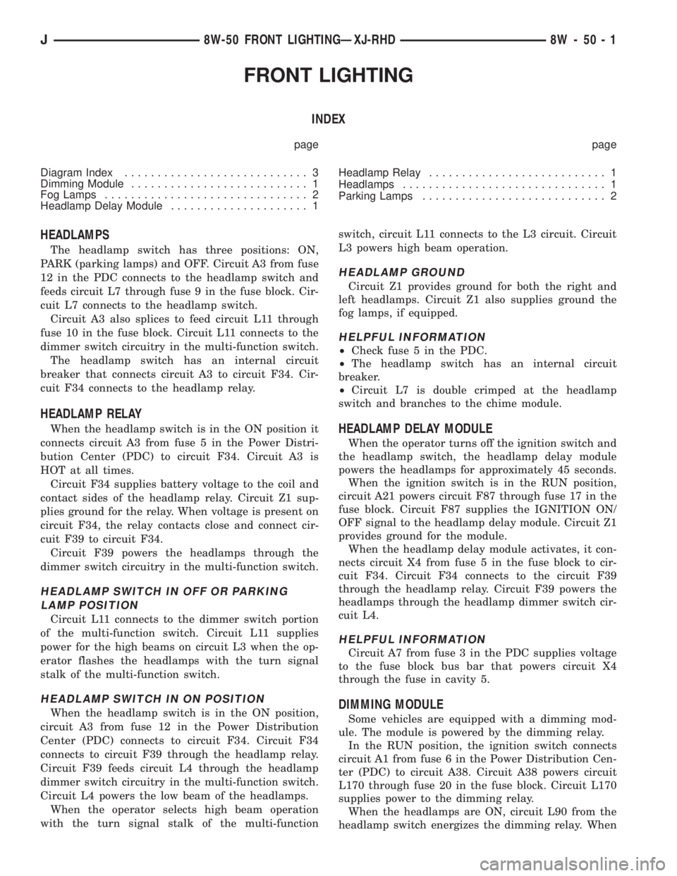
FRONT LIGHTING
INDEX
page page
Diagram Index............................ 3
Dimming Module........................... 1
Fog Lamps............................... 2
Headlamp Delay Module..................... 1Headlamp Relay........................... 1
Headlamps............................... 1
Parking Lamps............................ 2
HEADLAMPS
The headlamp switch has three positions: ON,
PARK (parking lamps) and OFF. Circuit A3 from fuse
12 in the PDC connects to the headlamp switch and
feeds circuit L7 through fuse 9 in the fuse block. Cir-
cuit L7 connects to the headlamp switch.
Circuit A3 also splices to feed circuit L11 through
fuse 10 in the fuse block. Circuit L11 connects to the
dimmer switch circuitry in the multi-function switch.
The headlamp switch has an internal circuit
breaker that connects circuit A3 to circuit F34. Cir-
cuit F34 connects to the headlamp relay.
HEADLAMP RELAY
When the headlamp switch is in the ON position it
connects circuit A3 from fuse 5 in the Power Distri-
bution Center (PDC) to circuit F34. Circuit A3 is
HOT at all times.
Circuit F34 supplies battery voltage to the coil and
contact sides of the headlamp relay. Circuit Z1 sup-
plies ground for the relay. When voltage is present on
circuit F34, the relay contacts close and connect cir-
cuit F39 to circuit F34.
Circuit F39 powers the headlamps through the
dimmer switch circuitry in the multi-function switch.
HEADLAMP SWITCH IN OFF OR PARKING
LAMP POSITION
Circuit L11 connects to the dimmer switch portion
of the multi-function switch. Circuit L11 supplies
power for the high beams on circuit L3 when the op-
erator flashes the headlamps with the turn signal
stalk of the multi-function switch.
HEADLAMP SWITCH IN ON POSITION
When the headlamp switch is in the ON position,
circuit A3 from fuse 12 in the Power Distribution
Center (PDC) connects to circuit F34. Circuit F34
connects to circuit F39 through the headlamp relay.
Circuit F39 feeds circuit L4 through the headlamp
dimmer switch circuitry in the multi-function switch.
Circuit L4 powers the low beam of the headlamps.
When the operator selects high beam operation
with the turn signal stalk of the multi-functionswitch, circuit L11 connects to the L3 circuit. Circuit
L3 powers high beam operation.
HEADLAMP GROUND
Circuit Z1 provides ground for both the right and
left headlamps. Circuit Z1 also supplies ground the
fog lamps, if equipped.
HELPFUL INFORMATION
²Check fuse 5 in the PDC.
²The headlamp switch has an internal circuit
breaker.
²Circuit L7 is double crimped at the headlamp
switch and branches to the chime module.
HEADLAMP DELAY MODULE
When the operator turns off the ignition switch and
the headlamp switch, the headlamp delay module
powers the headlamps for approximately 45 seconds.
When the ignition switch is in the RUN position,
circuit A21 powers circuit F87 through fuse 17 in the
fuse block. Circuit F87 supplies the IGNITION ON/
OFF signal to the headlamp delay module. Circuit Z1
provides ground for the module.
When the headlamp delay module activates, it con-
nects circuit X4 from fuse 5 in the fuse block to cir-
cuit F34. Circuit F34 connects to the circuit F39
through the headlamp relay. Circuit F39 powers the
headlamps through the headlamp dimmer switch cir-
cuit L4.
HELPFUL INFORMATION
Circuit A7 from fuse 3 in the PDC supplies voltage
to the fuse block bus bar that powers circuit X4
through the fuse in cavity 5.
DIMMING MODULE
Some vehicles are equipped with a dimming mod-
ule. The module is powered by the dimming relay.
In the RUN position, the ignition switch connects
circuit A1 from fuse 6 in the Power Distribution Cen-
ter (PDC) to circuit A38. Circuit A38 powers circuit
L170 through fuse 20 in the fuse block. Circuit L170
supplies power to the dimming relay.
When the headlamps are ON, circuit L90 from the
headlamp switch energizes the dimming relay. When
J8W-50 FRONT LIGHTINGÐXJ-RHD 8W - 50 - 1
Page 940 of 2158
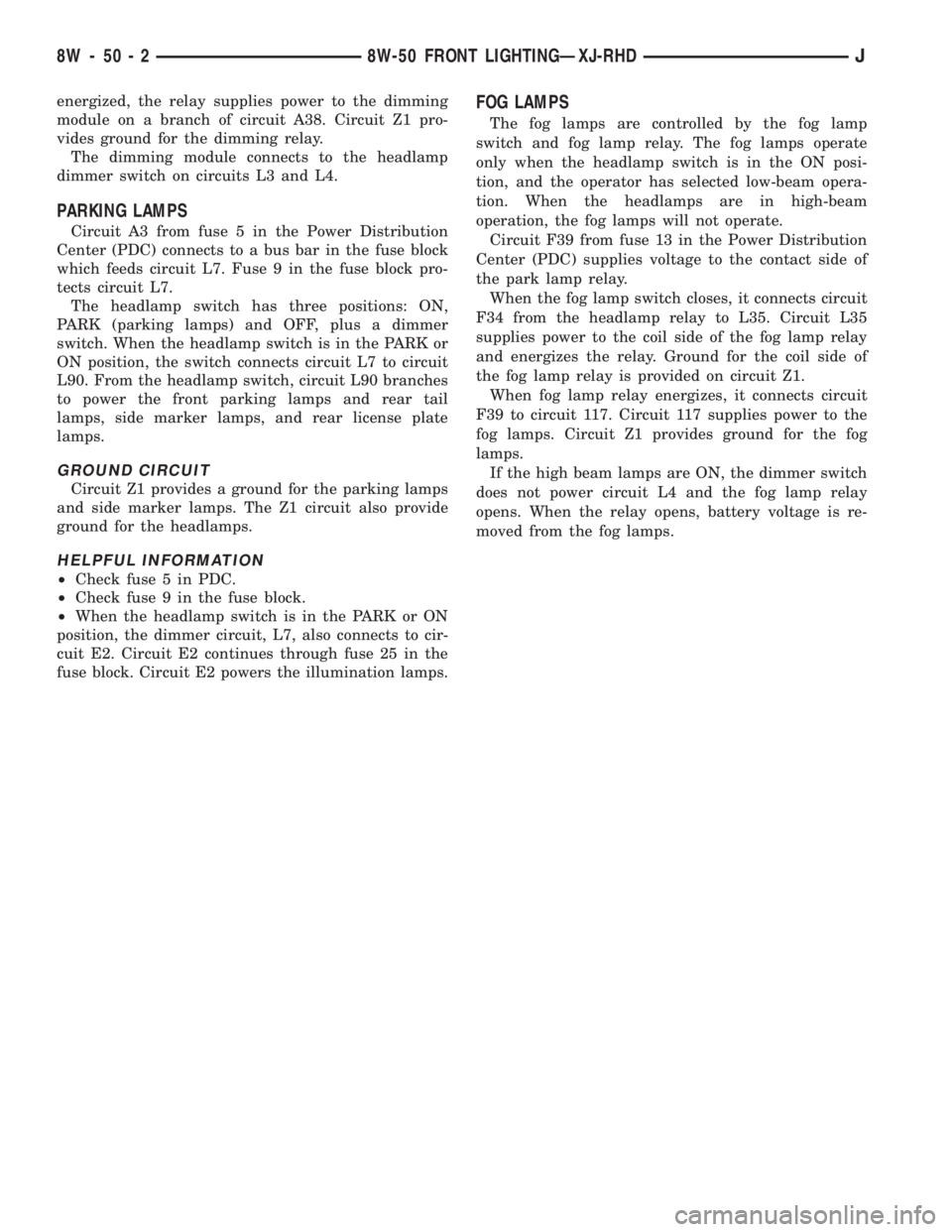
energized, the relay supplies power to the dimming
module on a branch of circuit A38. Circuit Z1 pro-
vides ground for the dimming relay.
The dimming module connects to the headlamp
dimmer switch on circuits L3 and L4.
PARKING LAMPS
Circuit A3 from fuse 5 in the Power Distribution
Center (PDC) connects to a bus bar in the fuse block
which feeds circuit L7. Fuse 9 in the fuse block pro-
tects circuit L7.
The headlamp switch has three positions: ON,
PARK (parking lamps) and OFF, plus a dimmer
switch. When the headlamp switch is in the PARK or
ON position, the switch connects circuit L7 to circuit
L90. From the headlamp switch, circuit L90 branches
to power the front parking lamps and rear tail
lamps, side marker lamps, and rear license plate
lamps.
GROUND CIRCUIT
Circuit Z1 provides a ground for the parking lamps
and side marker lamps. The Z1 circuit also provide
ground for the headlamps.
HELPFUL INFORMATION
²Check fuse 5 in PDC.
²Check fuse 9 in the fuse block.
²When the headlamp switch is in the PARK or ON
position, the dimmer circuit, L7, also connects to cir-
cuit E2. Circuit E2 continues through fuse 25 in the
fuse block. Circuit E2 powers the illumination lamps.
FOG LAMPS
The fog lamps are controlled by the fog lamp
switch and fog lamp relay. The fog lamps operate
only when the headlamp switch is in the ON posi-
tion, and the operator has selected low-beam opera-
tion. When the headlamps are in high-beam
operation, the fog lamps will not operate.
Circuit F39 from fuse 13 in the Power Distribution
Center (PDC) supplies voltage to the contact side of
the park lamp relay.
When the fog lamp switch closes, it connects circuit
F34 from the headlamp relay to L35. Circuit L35
supplies power to the coil side of the fog lamp relay
and energizes the relay. Ground for the coil side of
the fog lamp relay is provided on circuit Z1.
When fog lamp relay energizes, it connects circuit
F39 to circuit 117. Circuit 117 supplies power to the
fog lamps. Circuit Z1 provides ground for the fog
lamps.
If the high beam lamps are ON, the dimmer switch
does not power circuit L4 and the fog lamp relay
opens. When the relay opens, battery voltage is re-
moved from the fog lamps.
8W - 50 - 2 8W-50 FRONT LIGHTINGÐXJ-RHDJ
Page 941 of 2158
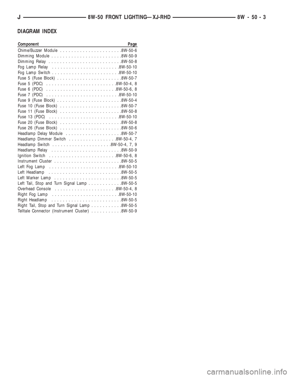
DIAGRAM INDEX
Component Page
Chime/Buzzer Module......................8W-50-6
Dimming Module.........................8W-50-9
Dimming Relay..........................8W-50-8
Fog Lamp Relay........................8W-50-10
Fog Lamp Switch........................8W-50-10
Fuse 5 (Fuse Block).......................8W-50-7
Fuse 5 (PDC).........................8W-50-4, 8
Fuse 6 (PDC).........................8W-50-6, 8
Fuse 7 (PDC)..........................8W-50-10
Fuse 9 (Fuse Block).......................8W-50-4
Fuse 10 (Fuse Block)......................8W-50-7
Fuse 11 (Fuse Block)......................8W-50-8
Fuse 13 (PDC).........................8W-50-10
Fuse 20 (Fuse Block)......................8W-50-8
Fuse 26 (Fuse Block)......................8W-50-6
Headlamp Delay Module....................8W-50-7
Headlamp Dimmer Switch.................8W-50-4, 7
Headlamp Switch.....................8W-50-4, 7, 9
Headlamp Relay.........................8W-50-9
Ignition Switch........................8W-50-6, 8
Instrument Cluster........................8W-50-5
Left Fog Lamp.........................8W-50-10
Left Headlamp..........................8W-50-5
Left Marker Lamp........................8W-50-5
Left Tail, Stop and Turn Signal Lamp............8W-50-5
Overhead Console......................8W-50-4, 8
Right Fog Lamp........................8W-50-10
Right Headlamp.........................8W-50-5
Right Tail, Stop and Turn Signal Lamp...........8W-50-5
Telltale Connector (Instrument Cluster)...........8W-50-9
J8W-50 FRONT LIGHTINGÐXJ-RHD 8W - 50 - 3
Page 1190 of 2158
FRONT LIGHTING
INDEX
page page
Daytime Running Lamp (DRL) ModuleÐCanadian
Vehicles Only........................... 2
Diagram Index............................ 2
Fog Lamps............................... 1Headlamps............................... 1
Parking Lamps............................ 1
HEADLAMPS
The headlamp switch has three positions: ON,
PARK (parking lamps) and OFF. Two circuits, L2 and
L20, connect the headlamp switch to the headlamp
dimmer/optical horn switch. The dimmer switch feeds
the low and high beams of the headlamps.
HEADLAMP SWITCH IN OFF OR PARKING
LAMP POSITION
Circuit A3 from fuse 7 in the Power Distribution
Center (PDC) supplies battery voltage to the head-
lamp switch. The headlamp switch has an internal
circuit breaker that connects circuit A3 to circuit
L20. The switch connects circuit A3 to circuit L2
when the headlamps are ON.
Circuit L20 connects to the dimmer switch. Circuit
L20 powers the high beams of the head lamps on cir-
cuit L3 when the operator flashes the headlamps
with the turn signal stalk.
HEADLAMP SWITCH IN ON POSITION
When the headlamp switch is in the ON position,
the A3 circuit from the PDC connects to circuit L2.
Circuit L2 connects to circuit L4 through the dimmer
switch. Circuit L4 powers the low beam of the head-
lamps.
When the operator selects high beam operation
with the turn signal stalk, the dimmer switch con-
nects circuit L20 to circuit L3. Circuit L3 supplies
battery voltage to the high beams.
HEADLAMP GROUND
Although circuit Z1 provides ground for both the
right and left headlamps, it has different termination
points for each. For the right headlamp, the Z1 cir-
cuit terminates at the radiator right support. For the
left headlamp, the Z1 circuit terminates at the left
radiator support.
HELPFUL INFORMATION
²Check fuse 7 in the PDC.
²The headlamp switch has an internal circuit
breaker.
²For the left front parking lamp, turn signal, side
marker lamp, headlamp, and fog lamp, circuit Z1 ter-
minates at the left radiator support.²For the right front parking lamp, turn signal, side
marker lamp, headlamp, and fog lamp, circuit Z1 ter-
minates at the right radiator support.
PARKING LAMPS
Circuit A6 from fuse 3 in the Power Distribution
Center (PDC) connects to the fuse block bus bar that
powers circuit F33. Fuse 8 in the fuse block protects
circuit F33. Circuit F33 connects to the headlamp
switch.
The headlamp switch has three positions: ON,
PARK (parking lamps) and OFF, plus a dimmer
switch. When the headlamp switch is in the PARK or
ON position, the switch connects circuit F33 to cir-
cuit L7. From the headlamp switch, circuit L7
branches to power the front parking lamps, rear tail
lamps, and side marker lamps. Circuit L7 also pow-
ers the park lamp relay, if equipped with fog lamps.
GROUND CIRCUIT
²For the left front parking lamp, turn signal, side
marker lamp, headlamp, and fog lamp, circuit Z1 ter-
minates at the left radiator support.
²For the right front parking lamp, turn signal, side
marker lamp, headlamp, and fog lamp, circuit Z1 ter-
minates at the right radiator support.
HELPFUL INFORMATION
²Check fuse 3 in the PDC.
²Check fuse 8 in the fuse block.
²Circuit L7 also feeds the radio, if equipped.
FOG LAMPS
The fog lamps are controlled by the fog lamp
switch and two relays. The fog lamps operate only
when the headlamp switch is in the ON position, and
the operator has selected low-beam operation. When
the headlamps are in high-beam operation, the fog
lamps will not operate.
When the headlamps or parking lamps are ON, cir-
cuit L7 from the headlamp switch supplies battery
voltage to the coil side of the park lamp relay. When
the operator presses the fog lamp switch, it provides
ground for the coil side of the park lamp relay. This
energizes the relay.
J8W-50 FRONT LIGHTINGÐYJ VEHICLES 8W - 50 - 1