1995 JEEP YJ fog light
[x] Cancel search: fog lightPage 464 of 2158

MULTI-FUNCTION SWITCH TESTING
PROCEDURESÐXJ
The multi-function switch contains electrical cir-
cuitry for:
²Headlamp Dimmer Switch.
²Passing Lights.
²Turn Signals.
²Hazard Warning.
²Windshield Wiper.
²Pulse Wiper.
²Windshield Washer.
This integrated switch is mounted to the left hand
side of the steering column. Should any function of
the switch fail, the entire switch must be replaced.
The multi-function switch also serves as a fog lamp
lock-out circuit. The circuit to the fog lamp switch is
completed only when the dimmer switch is in the low
beam position.
SWITCH TEST
(1) Disconnect battery negative cable.
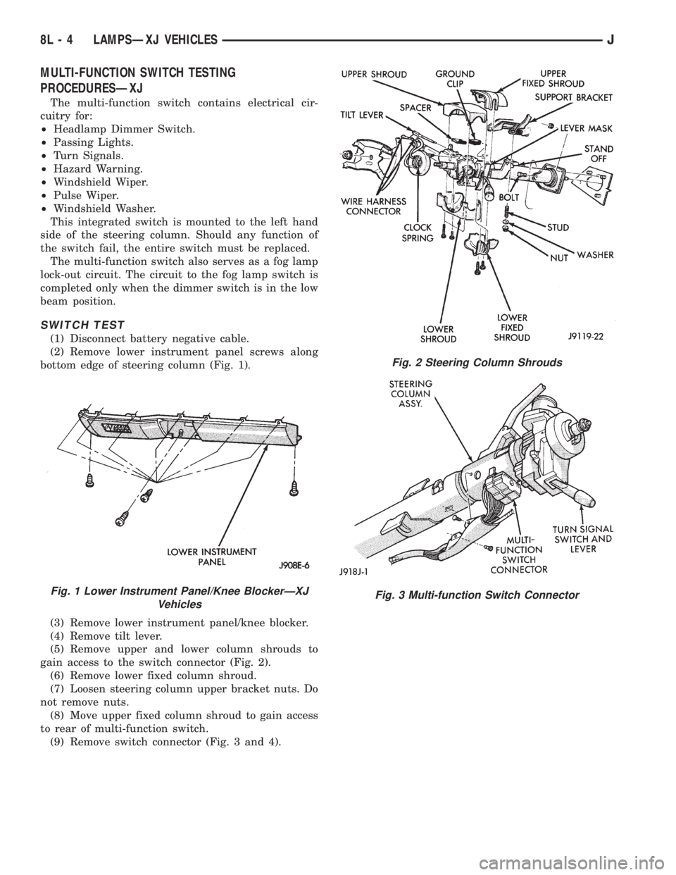
(2) Remove lower instrument panel screws along
bottom edge of steering column (Fig. 1).
(3) Remove lower instrument panel/knee blocker.
(4) Remove tilt lever.
(5) Remove upper and lower column shrouds to
gain access to the switch connector (Fig. 2).
(6) Remove lower fixed column shroud.
(7) Loosen steering column upper bracket nuts. Do
not remove nuts.
(8) Move upper fixed column shroud to gain access
to rear of multi-function switch.
(9) Remove switch connector (Fig. 3 and 4).
Fig. 1 Lower Instrument Panel/Knee BlockerÐXJ
Vehicles
Fig. 2 Steering Column Shrouds
Fig. 3 Multi-function Switch Connector
8L - 4 LAMPSÐXJ VEHICLESJ
Page 466 of 2158

SERVICE PROCEDURES
INDEX
page page
Back-Up/Rear Turn Signal/Tail Lamp Bulb
ReplacementÐXJ....................... 12
Center High Mounted Stop Lamp (CHMSL)ÐXJ . . 12
Daytime Running Lights (Canada Only)ÐXJ..... 15
Drl Module ReplacementÐXJ................ 15
Fog Lamp ReplacementÐXJ.................. 9
Fog Lamp Switch ReplacementÐXJ........... 10
Fog LampsÐXJ........................... 7
Front Park/Turn Signal Lamp Bulb
ReplacementÐXJ........................ 9
Headlamp Alignment PreparationÐXJ........... 6
Headlamp AlignmentÐXJ.................... 6
Headlamp Bulb ReplacementÐXJ.............. 7Headlamp Delay Function Trouble DiagnosisÐXJ . 14
Headlamp Delay Module ReplacementÐXJ...... 14
Headlamp SwitchÐXJ...................... 10
Headlamp/Fog Lamp Adjustment Using Alignment
ScreenÐXJ............................. 7
License Plate LampÐXJ.................... 12
Multi-Function Switch Service ProceduresÐXJ.... 11
Sentinel Headlamp Delay ModuleÐXJ.......... 14
Side Marker Lamp Bulb ReplacementÐXJ....... 10
Underhood Lamp Bulb ReplacementÐXJ....... 13
Underhood Lamp ReplacementÐXJ........... 13
Underhood Lamp Service InformationÐXJ....... 12
HEADLAMP ALIGNMENTÐXJ
Headlamps can be aligned using the screen method
provided in this section. Alignment Tool C4466-A or
equivalent can also be used. Refer to instructions
provided with the tool for proper procedures.The
preferred headlamp alignment setting is 0 for
the left/right adjustment and 1(down for the
up/down adjustment.
HEADLAMP ALIGNMENT PREPARATIONÐXJ
(1) Verify headlamp dimmer switch and high beam
indicator operation.
(2) Correct defective components that could hinder
proper headlamp alignment.
(3) Verify proper tire inflation.
(4) Clean headlamp lenses.
(5) Verify that luggage area is not heavily loaded.
Fig. 1 Headlamp Alignment ScreenÐTypical
8L - 6 LAMPSÐXJ VEHICLESJ
Page 478 of 2158

BULB APPLICATIONÐXJ VEHICLES
GENERAL INFORMATION
The following Bulb Application Table lists the lamp
title on the left side of the column and trade number
or part number on the right.
CAUTION: Do not use bulbs that have a higher can-
dle power than the bulb listed in the Bulb Applica-
tion Table. Damage to lamp can result.
Do not touch halogen bulbs with fingers or other
oily surfaces. Bulb life will be reduced.
EXTERIOR LAMPSÐXJ
Back-up .................................................................1156
Center High Mounted Stoplamp ..........................922
Fog ............................................................................H3
Front Side Marker .................................................194
Headlamp/Sealed Beam....................................H6054
License Plate ..........................................................168
License Plate W/Outside Spare ..............................67
Park/Turn Signal ............................................2057NA
Tail/Stop ................................................................2057
Turn Signal ...........................................................1156
INTERIOR LAMPSÐXJ
Service procedures for most of the lamps in the in-
strument panel, Instrument cluster and switches are
located in Group 8E, Instrument Panel and Gauges.
Some components have lamps that can only be ser-
viced by an Authorized Service Center (ASC) after
the component is removed from the vehicle. Contact
local dealer for location of nearest ASC.
Cargo .......................................................................561
Dome .......................................................................561
Dome/Reading.........................................................906Glove Compartment ...............................................194
Overhead Console ..................................................912
Under Hood ............................................................105
Vanity Mirror ...........................................................74
Underpanel Courtesy.............................................168
INDICATOR LAMPS
Service procedures for most of the lamps in the in-
strument panel, instrument cluster and switches are
located in Group 8E, Instrument Panel and Gauges.
A/C Control ...............................................................74
Airbag ........................................................................74
Anti-lock Brake ........................................................74
Ash Receiver .........................................................1891
Brake Warning .........................................................74
Check Engine ...........................................................74
Cigar Lighter ............................................................53
Diesel Wait ...............................................................74
Fasten Seat Belts ....................................................74
Four Wheel Drive ....................................................74
Generator ................................................................194
Generator/Diesel.......................................................74
Heater Control .........................................................74
High Beam..............................................................194
Illumination ............................................................194
Low Fuel .................................................................194
Low Washer Fluid....................................................74
Radio ......................................................................ASC
Rocker Switch...........................................................37
Seat Belt ...................................................................74
Transfer Case .........................................................658
Transmission Floor Shift.......................................658
Turn Signal.............................................................194
Shift ...........................................................................74
Water In Fuel ...........................................................74
8L - 18 LAMPSÐXJ VEHICLESJ
Page 482 of 2158

SERVICE PROCEDURES
INDEX
page page
Back-Up/Rear Turn Signal/Tail Lamp Bulb
ReplacementÐYJ....................... 28
Center High Mounted Stop Lamp (CHMSL)ÐYJ . . 28
Daytime Running Lights (Canada Only)ÐYJ..... 30
Drl Module ReplacementÐYJ................ 30
Fog Lamp ReplacementÐYJ................. 25
Fog Lamp Switch ReplacementÐYJ........... 26
Fog LampsÐYJ.......................... 23
Front Park/Turn Signal Lamp Bulb ReplacementÐ
YJ ................................... 25
Headlamp Alignment PreparationÐYJ.......... 22Headlamp AlignmentÐYJ................... 22
Headlamp Bulb ReplacementÐYJ............. 23
Headlamp Dimmer Switch ReplacementÐYJ..... 26
Headlamp SwitchÐYJ...................... 26
Headlamp/Fog Lamp Adjustment Using Alignment
ScreenÐYJ............................ 23
Side Marker Lamp Bulb ReplacementÐYJ....... 25
Underhood Lamp Bulb ReplacementÐYJ....... 29
Underhood Lamp ReplacementÐYJ........... 29
Underhood Lamp Service InformationÐYJ....... 28
HEADLAMP ALIGNMENTÐYJ
Headlamps can be aligned using the screen method
provided in this section. Alignment Tool C4466-A or
equivalent can also be used. Refer to instructions
provided with the tool for proper procedures.The
preferred headlamp alignment setting is 0 for
the left/right adjustment and 1(down for the
up/down adjustment.
HEADLAMP ALIGNMENT PREPARATIONÐYJ
(1) Verify headlamp dimmer switch and high beam
indicator operation.
(2) Correct defective components that could hinder
proper headlamp alignment.
(3) Verify proper tire inflation.
(4) Clean headlamp lenses.
(5) Verify that luggage area is not heavily loaded.
(6) Fuel tank should be FULL. Add 2.94 kg (6.5
lbs.) of weight over the fuel tank for each estimated
gallon of missing fuel.
Fig. 1 Headlamp Alignment ScreenÐTypical
8L - 22 LAMPSÐYJ VEHICLESJ
Page 492 of 2158

BULB APPLICATIONÐYJ VEHICLES
GENERAL INFORMATION
The following Bulb Application Table lists the lamp
title on the left side of the column and trade number
or part number on the right.
CAUTION: Do not use bulbs that have a higher can-
dle power than the bulb listed in the Bulb Applica-
tion Table. Damage to lamp can result.
Do not touch halogen bulbs with fingers or other
oily surfaces. Bulb life will be reduced.
EXTERIOR LAMPSÐYJ
Back-up .................................................................1156
Center High Mounted Stoplamp ..........................912
Fog ............................................................................H3
Front Side Marker .................................................194
Headlamp/Sealed Beam....................................H6054
Park/Turn Signal..................................................3157
Tail/Stop ................................................................1157
INTERIOR LAMPSÐYJ
Service procedures for most of the lamps in the in-
strument panel, Instrument cluster and switches are
located in Group 8E, Instrument Panel and Gauges.
Some components have lamps that can only be ser-
viced by an Authorized Service Center (ASC) after
the component is removed from the vehicle. Contact
local dealer for location of nearest ASC.Dome/Cargo .........................................................212-2
Glove Compartment ...............................................194
Under Hood ............................................................105
Underpanel Courtesy...............................................89
INDICATOR LAMPS
Service procedures for most of the lamps in the in-
strument panel, instrument cluster and switches are
located in Group 8E, Instrument Panel and Gauges.
A/C Control ...............................................................74
Anti-lock Brake ........................................................74
Ash Receiver .........................................................1891
Brake Warning .........................................................74
Cigar Lighter ............................................................53
Fasten Seat Belts ....................................................74
Four Wheel Drive ....................................................74
Generator ................................................................194
Hazard.......................................................................74
Heater Control .......................................................194
High Beam..............................................................194
Illumination ............................................................194
Low Coolant..............................................................74
Radio ......................................................................ASC
Rocker Switch...........................................................74
Seat Belt ...................................................................74
Shift ...........................................................................74
Turn Signal.............................................................194
8L - 32 LAMPSÐYJ VEHICLESJ
Page 497 of 2158

REAR WINDOW DEFOGGER
CONTENTS
page page
DIAGNOSIS............................. 1
GENERAL INFORMATION.................. 1SERVICE PROCEDURES................... 3
GENERAL INFORMATION
The electrically-heated rear window defogger is an
available option on XJ (Cherokee), and YJ (Wrangler)
models equipped with the hardtop roof option. Fol-
lowing are general descriptions of the major compo-
nents in the rear window defogger system. Refer to
Group 8W - Wiring Diagrams for complete circuit de-
scriptions and diagrams.
REAR WINDOW GLASS GRID
The heated rear window glass has two electrically-
conductive vertical bus bars and a series of horizon-
tal grid lines made of a silver-ceramic material,
which is baked on and bonded to the inside surface of
the glass. The grid lines and bus bars comprise a
parallel electrical circuit.
When the rear window defogger switch is placed in
the ON position, current is directed to the rear win-
dow grid lines through the bus bars. The grid lines
heat the rear window to clear the surface of fog or
snow. Circuit protection for the heated grid circuit is
provided by fuse 18 (XJ) or fuse 6 (YJ) in the fuse-
block module.
The grid lines and bus bars are highly resistant to
abrasion. However, it is possible for an open to occur
in an individual grid line resulting in no current flow
through the line. The grid lines can be damaged or
scraped off with sharp instruments. Care should be
taken in cleaning the glass or removing foreign ma-
terials, decals or stickers. Normal glass cleaning sol-
vents or hot water used with rags or toweling is
recommended.A repair kit is available to repair the grid lines and
bus bars, or to reinstall the heated glass pigtail
wires.
DEFOGGER SWITCH
The rear window defogger switch is mounted in the
instrument panel left of the steering column for XJ,
or right of the steering column for YJ. The switch cir-
cuit is protected by fuse 8 (XJ) or fuse 9 (YJ) in the
fuseblock module. Actuating the switch energizes the
relay and electronic timer. A light-emitting diode
(LED) in the switch (XJ), or a indicator lamp in the
switch (YJ), illuminates to indicate when the system
is turned on. The defogger switch can not be re-
paired. If faulty, the switch must be replaced.
DEFOGGER RELAY/TIMER
The defogger relay/timer is located in the relay cen-
ter on XJ models, or taped to the instrument panel
wiring harness behind the parking brake pedal in the
left cowl side area on YJ models. When the rear de-
fogger switch is actuated, the rear defogger relay is
energized. This causes current to flow through the
grid circuit for approximately 10 minutes, or until
the rear window defogger switch or ignition switch
are turned off.
DIAGNOSIS
SYSTEM TESTS
Electrically-heated rear window defogger operation
can be confirmed in the following manner:
(1) Turn the ignition switch to the ON position.
(2) Turn rear window defogger control switch ON.
(3) Monitor vehicle voltmeter. With the control
switch ON, a distinct needle deflection should be
noted.(4) The rear window defogger operation can be
checked by feeling the glass. A distinct difference in
temperature between the grid lines and adjacent
clear glass can be detected within 3 to 4 minutes of
operation.
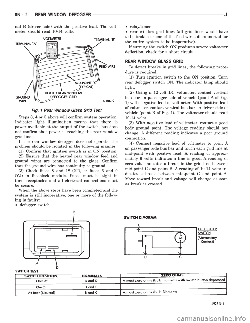
(5) Using a DC voltmeter, contact terminal A (Fig.
1) (passenger side) with the negative lead, and termi-
JREAR WINDOW DEFOGGER 8N - 1
Page 498 of 2158

nal B (driver side) with the positive lead. The volt-
meter should read 10-14 volts.
Steps 3, 4 or 5 above will confirm system operation.
Indicator light illumination means that there is
power available at the output of the switch, but does
not confirm that power is reaching the rear window
grid lines.
If the rear window defogger does not operate, the
problem should be isolated in the following manner:
(1) Confirm that ignition switch is in ON position.
(2) Ensure that the heated rear window feed and
ground wires are connected to the glass. Confirm
that the ground wire has continuity to ground.
(3) Check fuses 8 and 18 (XJ), or fuses 6 and 9
(YJ) in fuseblock module. Fuses must be tight in
their receptacles and all electrical connections must
be secure.
When the above steps have been completed and the
system is still inoperative, one or more of the follow-
ing is faulty:
²defogger switch²relay/timer
²rear window grid lines (all grid lines would have
to be broken or one of the feed wires disconnected for
the entire system to be inoperative).
If turning the switch ON produces severe voltmeter
deflection, check for a short circuit.
REAR WINDOW GLASS GRID
To detect breaks in grid lines, the following proce-
dure is required:
(1) Turn ignition switch to the ON position. Turn
rear defogger switch ON. The indicator lamp should
light.
(2) Using a 12-volt DC voltmeter, contact vertical
bus bar on passenger side of vehicle (point A of Fig.
1) with negative lead of voltmeter. With positive lead
of voltmeter, contact vertical bus bar on driver side of
vehicle (point B of Fig. 1). The voltmeter should read
10-14 volts.
(3) With negative lead of voltmeter, contact a good
body ground point. The voltage reading should not
change. A different reading indicates a poor ground
connection.
(4) Connect negative lead of voltmeter to point A
on passenger side bus bar and touch each grid line at
mid-point with positive lead. A reading of approxi-
mately 6 volts indicates a line is good. A reading of
zero volts indicates a break in the grid line between
mid-point C and point B. A reading of 10-14 volts in-
dicates a break between mid-point C and point A.
Move toward break and voltage will change as soon
as break is crossed.
Fig. 1 Rear Window Glass Grid Test
8N - 2 REAR WINDOW DEFOGGERJ
Page 500 of 2158

(9) Allow epoxy to cure 24 hours at room tempera-
ture or use heat gun with a 260É-371ÉC (500É-700ÉF)
range for 15 minutes. Hold gun approximately
254mm (10 inches) from repaired area.
(10) After conductive epoxy is properly cured re-
move wedge or clamp from terminal or pigtail and
check operation of rear window defogger. Do not at-
tach connectors until curing is complete.
DEFOGGER SWITCH REMOVE/INSTALL
XJ MODELS
(1) Remove the instrument cluster bezel. Refer to
Group 8E - Instrument Panel and Gauges for proce-
dure.
(2) Remove the switch housing panel.
(3) Unplug the switch connector. Slightly depress
the switch mounting tabs and remove the switch.
(4) Reverse removal procedures to install.
YJ MODELS
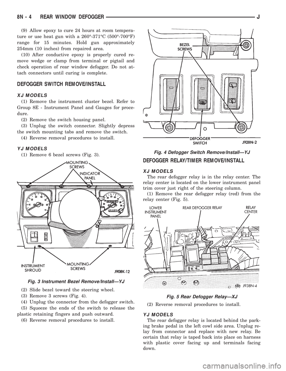
(1) Remove 6 bezel screws (Fig. 3).
(2) Slide bezel toward the steering wheel.
(3) Remove 3 screws (Fig. 4).
(4) Unplug the connector from the defogger switch.
(5) Squeeze the ends of the switch to release the
plastic retaining fingers and push outward.
(6) Reverse removal procedures to install.
DEFOGGER RELAY/TIMER REMOVE/INSTALL
XJ MODELS
The rear defogger relay is in the relay center. The
relay center is located on the lower instrument panel
trim cover just right of the steering column.
(1) Remove the rear defogger relay (red) from the
relay center (Fig. 5).
(2) Reverse removal procedures to install.
YJ MODELS
The rear defogger relay is located behind the park-
ing brake pedal in the left cowl side area. Unplug re-
lay from connector and replace with new relay. Be
certain that relay is taped back into place on harness
with plastic cover facing up and terminals facing
down.
Fig. 3 Instrument Bezel Remove/InstallÐYJ
Fig. 4 Defogger Switch Remove/InstallÐYJ
Fig. 5 Rear Defogger RelayÐXJ
8N - 4 REAR WINDOW DEFOGGERJ