1995 JEEP YJ Gages
[x] Cancel search: GagesPage 2002 of 2158

REAR SEATBACK LATCH STRIKER AND BUMPERÐ
XJ
REMOVAL
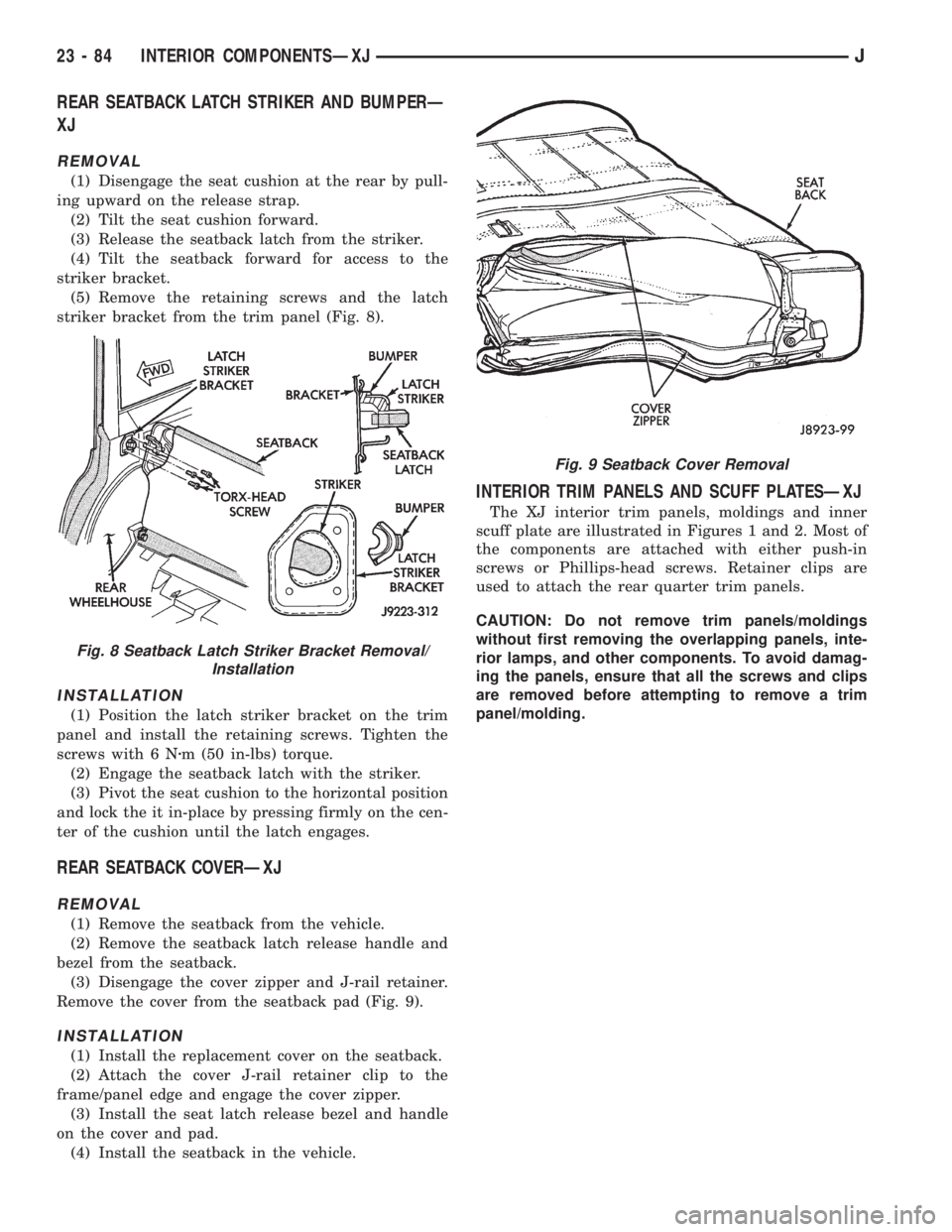
(1) Disengage the seat cushion at the rear by pull-
ing upward on the release strap.
(2) Tilt the seat cushion forward.
(3) Release the seatback latch from the striker.
(4) Tilt the seatback forward for access to the
striker bracket.
(5) Remove the retaining screws and the latch
striker bracket from the trim panel (Fig. 8).
INSTALLATION
(1) Position the latch striker bracket on the trim
panel and install the retaining screws. Tighten the
screws with 6 Nzm (50 in-lbs) torque.
(2) Engage the seatback latch with the striker.
(3) Pivot the seat cushion to the horizontal position
and lock the it in-place by pressing firmly on the cen-
ter of the cushion until the latch engages.
REAR SEATBACK COVERÐXJ
REMOVAL
(1) Remove the seatback from the vehicle.
(2) Remove the seatback latch release handle and
bezel from the seatback.
(3) Disengage the cover zipper and J-rail retainer.
Remove the cover from the seatback pad (Fig. 9).
INSTALLATION
(1) Install the replacement cover on the seatback.
(2) Attach the cover J-rail retainer clip to the
frame/panel edge and engage the cover zipper.
(3) Install the seat latch release bezel and handle
on the cover and pad.
(4) Install the seatback in the vehicle.
INTERIOR TRIM PANELS AND SCUFF PLATESÐXJ
The XJ interior trim panels, moldings and inner
scuff plate are illustrated in Figures 1 and 2. Most of
the components are attached with either push-in
screws or Phillips-head screws. Retainer clips are
used to attach the rear quarter trim panels.
CAUTION: Do not remove trim panels/moldings
without first removing the overlapping panels, inte-
rior lamps, and other components. To avoid damag-
ing the panels, ensure that all the screws and clips
are removed before attempting to remove a trim
panel/molding.
Fig. 8 Seatback Latch Striker Bracket Removal/
Installation
Fig. 9 Seatback Cover Removal
23 - 84 INTERIOR COMPONENTSÐXJJ
Page 2049 of 2158

INSTALLATION
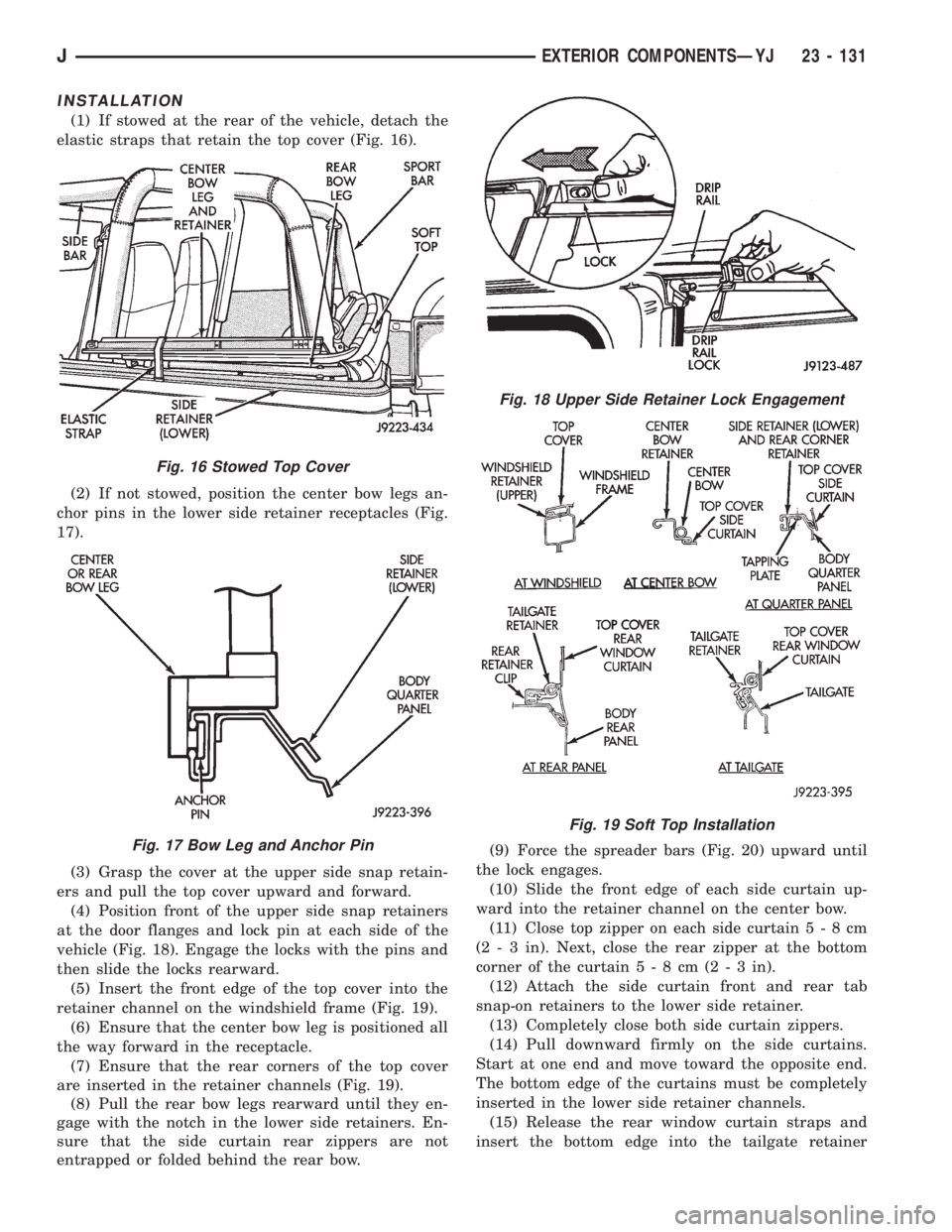
(1) If stowed at the rear of the vehicle, detach the
elastic straps that retain the top cover (Fig. 16).
(2) If not stowed, position the center bow legs an-
chor pins in the lower side retainer receptacles (Fig.
17).
(3) Grasp the cover at the upper side snap retain-
ers and pull the top cover upward and forward.
(4) Position front of the upper side snap retainers
at the door flanges and lock pin at each side of the
vehicle (Fig. 18). Engage the locks with the pins and
then slide the locks rearward.
(5) Insert the front edge of the top cover into the
retainer channel on the windshield frame (Fig. 19).
(6) Ensure that the center bow leg is positioned all
the way forward in the receptacle.
(7) Ensure that the rear corners of the top cover
are inserted in the retainer channels (Fig. 19).
(8) Pull the rear bow legs rearward until they en-
gage with the notch in the lower side retainers. En-
sure that the side curtain rear zippers are not
entrapped or folded behind the rear bow.(9) Force the spreader bars (Fig. 20) upward until
the lock engages.
(10) Slide the front edge of each side curtain up-
ward into the retainer channel on the center bow.
(11) Close top zipper on each side curtain5-8cm
(2 - 3 in). Next, close the rear zipper at the bottom
corner of the curtain5-8cm(2-3in).
(12) Attach the side curtain front and rear tab
snap-on retainers to the lower side retainer.
(13) Completely close both side curtain zippers.
(14) Pull downward firmly on the side curtains.
Start at one end and move toward the opposite end.
The bottom edge of the curtains must be completely
inserted in the lower side retainer channels.
(15) Release the rear window curtain straps and
insert the bottom edge into the tailgate retainer
Fig. 16 Stowed Top Cover
Fig. 17 Bow Leg and Anchor Pin
Fig. 18 Upper Side Retainer Lock Engagement
Fig. 19 Soft Top Installation
JEXTERIOR COMPONENTSÐYJ 23 - 131
Page 2092 of 2158

REFRIGERANT OIL
It is important to have the correct amount of oil in
the A/C system. This will ensure proper lubrication of
the compressor. Too little oil will result in damage to
the compressor. Too much oil will reduce the cooling
capacity of the system.
The oil used in the SD7H15 compressor is a poly-
alkylene glycol synthetic oil SP-20 PAG, wax-free re-
frigerant oil. Only refrigerant oil of the same type
should be used to service the system. Do not use any
other oil. The oil container should be kept tightly
capped until it is ready for use and then capped after
use to prevent contamination. Refrigerant oil will
quickly absorb any moisture it comes in contact with.
OIL LEVEL CHECK
It will not be necessary to check oil level in the
compressor or to add oil unless there has been an oil
loss. This may be due to a rupture or leak from a
line, shaft seal, evaporator or condenser. Oil loss at a
leak point will be evident by the presence of a wet,
shiny surface around the leak.
When an A/C system is assembled at the factory,
all components (except the compressor) are refriger-
ant oil free. After the system has been charged and
operated, the oil in the compressor is dispersed
through the system. The receiver-drier, evaporator,
condenser and compressor will retain a significant
amount of oil.
Refrigerant oil must be added when a receiver-
drier, evaporator, condenser or compressor are re-
placed. When the compressor is replaced, the oil
must be drained from the replaced compressor and
measured. Drain all the oil from the new compressor.
Add back into the new compressor the amount of oil
that was drained out of the old compressor.
Add an additional 30 ml (1 fluid oz.) of com-
pressor oil to the system when a receiver-drier,
condenser or evaporator is replaced.
AIR CONDITIONING PERFORMANCE TESTS
Humidity has an important bearing on the temper-
ature of the air delivered to the vehicle's interior. It
is important to understand the effect humidity has
on the performance of the system. When humidity is
high, the evaporator has to perform a double duty. It
must lower the air temperature and the temperature
of the moisture carried in the air. Condensing the
moisture in the air transfers a great deal of heat en-
ergy into the evaporator fins and tubing. This re-
duces the amount of heat the evaporator can absorb
from the air. High humidity greatly reduces the evap-
orator's ability to lower the temperature of the air.Evaporator capacity used to reduce the amount of
moisture in the air is not wasted. Wringing some of
the moisture out of the air entering the vehicle adds
to the comfort of the passengers. However, an owner
may expect too much from their air conditioning sys-
tem on humid days. A performance test is the best
way to determine whether or not the system is per-
forming up to standard. This test also provides valu-
able clues to the possible cause of trouble.
Air temperature in test room must be 21ÉC (70ÉF)
minimum for this test.
(1) Connect a Tachometer and manifold gauge set.
(2) Set A/C controls to Max A/C, temperature lever
on full cool and blower on high.
(3) Start engine and adjust idle to 1,000 RPM with
A/C clutch engaged.
(4) Engine should be warmed up with doors, win-
dows and hood closed.
(5) Insert a thermometer in the left center A/C out-
let. Operate the A/C and engine for 5 minutes. The
A/C clutch may cycle depending on ambient temper-
atures.
(6) After 5 minutes note the discharge air temper-
ature. If the clutch cycles, take the reading before
the clutch disengages.
(7) On LHD XJ vehicles open the hood and discon-
nect vacuum line going to the heater water control
valve. Observe the valve arm for movement as the
line is disconnected. Plug the vacuum line to prevent
leakage. If it does not move repair vacuum circuit.
(8) Operate the A/C for 2 more minutes and take
the discharge air temperature reading again. On XJ
vehicles if the temperature increased by more than
2ÉC (5ÉF) check the blend air door cable for correct
operation.
(9) Compare the discharge air temperature to the
A/C Performance (Temperature and Pressure) Chart.
If the discharge air temperature is high, refer to Re-
frigerant Leak Testing and Refrigerant System Diag-
nosis Chart.
(10) Compare the compressor discharge and suc-
tion pressures to the A/C Performance (Temperature
and Pressure) Chart. If the compressor discharge or
suction pressure is not normal, check the operation of
the refrigerant system. Refer to Refrigerant System
Diagnosis Chart.
If pressures are abnormal, refer to the Pressure
and Performance Diagnosis Charts.
The following chart have been developed for quick
reference.
24 - 12 HEATING AND AIR CONDITIONINGJ