1995 JEEP YJ transmission
[x] Cancel search: transmissionPage 1379 of 2158
INSTALLATION
(1) Assemble exhaust pipe to manifold and cata-
lytic converter loosely to permit proper alignment of
all parts.
(2) Use a new clamp and tighten the nuts to 61
Nzm (45 ft. lbs.) torque.
(3) Connect the exhaust pipe to the engine exhaust
manifold. Install a new seal between the exhaust
manifold and the exhaust pipe (4.0L engine, only).
Tighten the nuts to 31 Nzm (23 ft. lbs.) torque (Fig.
1).
(3) Install the rear crossmember. Tighten the
crossmember-to-sill bolts to 41 Nzm (30 ft. lbs.)
torque. Remove the support from the transmission.
(4) Coat the oxygen sensor with anti-seize com-
pound. Install the sensor and tighten the nut to 48
Nzm (35 ft. lbs.) torque.
(5) Lower the vehicle.
(6) Start the engine and inspect for exhaust leaks
and exhaust system contact with the body panels.
Adjust the alignment, if needed.
EXHAUST PIPEÐYJ VEHICLES
WARNING: IF TORCHES ARE USED WHEN WORK-
ING ON THE EXHAUST SYSTEM, DO NOT ALLOW
THE FLAME NEAR THE FUEL LINES.
REMOVAL
(1) Raise and support the vehicle.
(2) Saturate the bolts and nuts with heat valve lu-
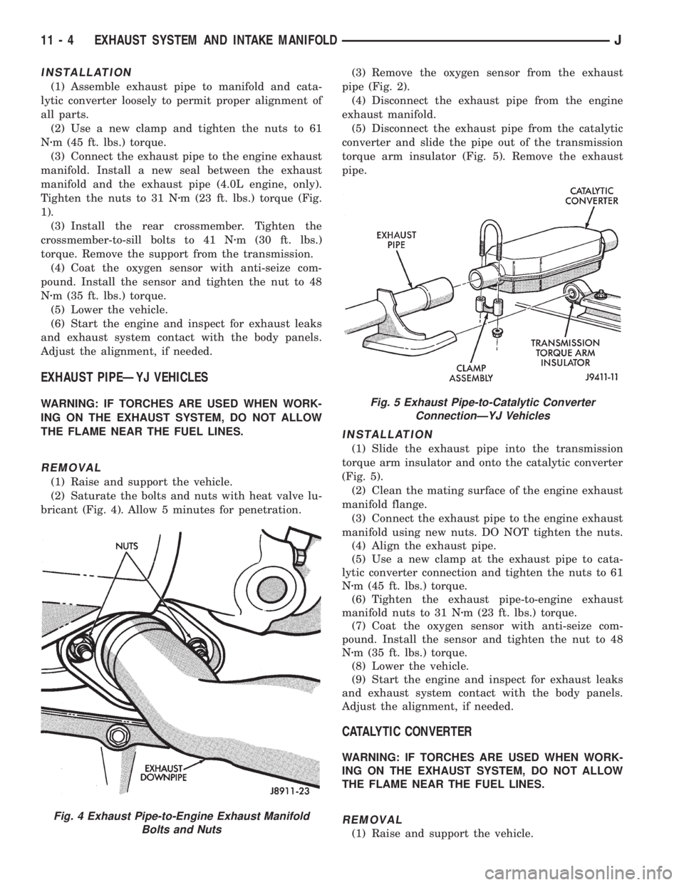
bricant (Fig. 4). Allow 5 minutes for penetration.(3) Remove the oxygen sensor from the exhaust
pipe (Fig. 2).
(4) Disconnect the exhaust pipe from the engine
exhaust manifold.
(5) Disconnect the exhaust pipe from the catalytic
converter and slide the pipe out of the transmission
torque arm insulator (Fig. 5). Remove the exhaust
pipe.
INSTALLATION
(1) Slide the exhaust pipe into the transmission
torque arm insulator and onto the catalytic converter
(Fig. 5).
(2) Clean the mating surface of the engine exhaust
manifold flange.
(3) Connect the exhaust pipe to the engine exhaust
manifold using new nuts. DO NOT tighten the nuts.
(4) Align the exhaust pipe.
(5) Use a new clamp at the exhaust pipe to cata-
lytic converter connection and tighten the nuts to 61
Nzm (45 ft. lbs.) torque.
(6) Tighten the exhaust pipe-to-engine exhaust
manifold nuts to 31 Nzm (23 ft. lbs.) torque.
(7) Coat the oxygen sensor with anti-seize com-
pound. Install the sensor and tighten the nut to 48
Nzm (35 ft. lbs.) torque.
(8) Lower the vehicle.
(9) Start the engine and inspect for exhaust leaks
and exhaust system contact with the body panels.
Adjust the alignment, if needed.
CATALYTIC CONVERTER
WARNING: IF TORCHES ARE USED WHEN WORK-
ING ON THE EXHAUST SYSTEM, DO NOT ALLOW
THE FLAME NEAR THE FUEL LINES.
REMOVAL
(1) Raise and support the vehicle.
Fig. 4 Exhaust Pipe-to-Engine Exhaust Manifold
Bolts and Nuts
Fig. 5 Exhaust Pipe-to-Catalytic Converter
ConnectionÐYJ Vehicles
11 - 4 EXHAUST SYSTEM AND INTAKE MANIFOLDJ
Page 1384 of 2158
(2) Remove air cleaner inlet hose from throttle
plate assembly.
(3) Remove the air cleaner assembly.
(4) Remove the throttle cable, cruise control cable
(if equipped) and the transmission line pressure ca-
ble.
(5) Disconnect all electrical connectors on the in-
take manifold.
(6) Disconnect and remove the fuel supply and re-
turn lines from the fuel rail assembly (refer to Group
14, Fuel System).
(7) Loosen the accessory drive belt (refer to Group
7, Cooling System). Loosen the tensioner.
(8) Remove the power steering pump and bracket
from the intake manifold and set aside.
(9) Remove the fuel rail and injectors (refer to
Group 14, Fuel System).
(10) Raise the vehicle.
(11) Disconnect the exhaust pipe from the engine
exhaust manifold. Discard the seal.
(12) Lower the vehicle.
(13) Remove the intake manifold and engine ex-
haust manifold.
CLEANING
Clean the mating surfaces of the cylinder head and
the manifold if the original manifold is to be in-
stalled.
If the manifold is being replaced, ensure all the fit-
ting, etc. are transferred to the replacement mani-
fold.
INSTALLATION
(1) Install a new exhaust/intake manifold gasket
over the alignment dowels on the cylinder head.
(2) Position the engine exhaust manifold to the cyl-
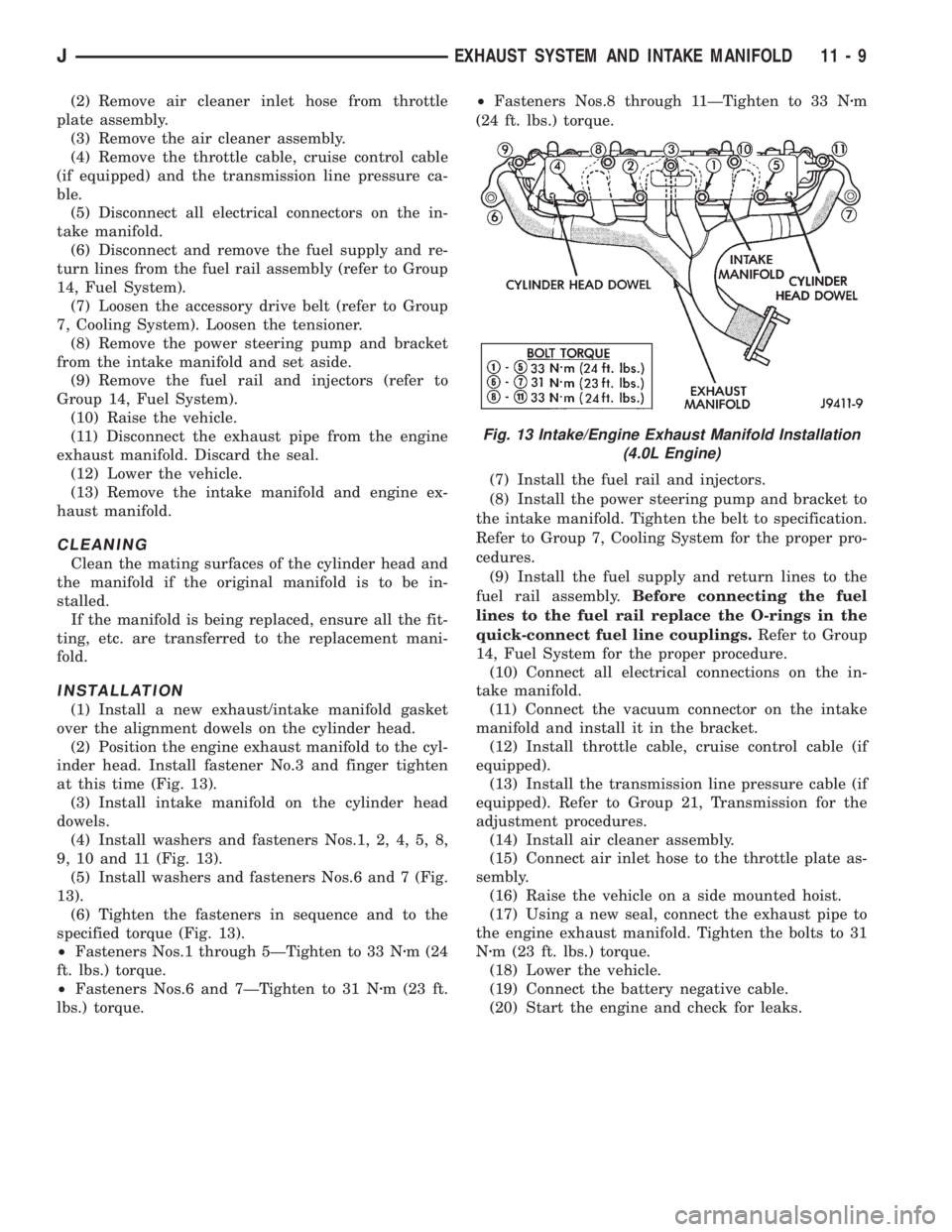
inder head. Install fastener No.3 and finger tighten
at this time (Fig. 13).
(3) Install intake manifold on the cylinder head
dowels.
(4) Install washers and fasteners Nos.1, 2, 4, 5, 8,
9, 10 and 11 (Fig. 13).
(5) Install washers and fasteners Nos.6 and 7 (Fig.
13).
(6) Tighten the fasteners in sequence and to the
specified torque (Fig. 13).
²Fasteners Nos.1 through 5ÐTighten to 33 Nzm (24
ft. lbs.) torque.
²Fasteners Nos.6 and 7ÐTighten to 31 Nzm (23 ft.
lbs.) torque.²Fasteners Nos.8 through 11ÐTighten to 33 Nzm
(24 ft. lbs.) torque.
(7) Install the fuel rail and injectors.
(8) Install the power steering pump and bracket to
the intake manifold. Tighten the belt to specification.
Refer to Group 7, Cooling System for the proper pro-
cedures.
(9) Install the fuel supply and return lines to the
fuel rail assembly.Before connecting the fuel
lines to the fuel rail replace the O-rings in the
quick-connect fuel line couplings.Refer to Group
14, Fuel System for the proper procedure.
(10) Connect all electrical connections on the in-
take manifold.
(11) Connect the vacuum connector on the intake
manifold and install it in the bracket.
(12) Install throttle cable, cruise control cable (if
equipped).
(13) Install the transmission line pressure cable (if
equipped). Refer to Group 21, Transmission for the
adjustment procedures.
(14) Install air cleaner assembly.
(15) Connect air inlet hose to the throttle plate as-
sembly.
(16) Raise the vehicle on a side mounted hoist.
(17) Using a new seal, connect the exhaust pipe to
the engine exhaust manifold. Tighten the bolts to 31
Nzm (23 ft. lbs.) torque.
(18) Lower the vehicle.
(19) Connect the battery negative cable.
(20) Start the engine and check for leaks.
Fig. 13 Intake/Engine Exhaust Manifold Installation
(4.0L Engine)
JEXHAUST SYSTEM AND INTAKE MANIFOLD 11 - 9
Page 1388 of 2158
TRANSFER CASE SKID PLATE
REMOVAL
(1) Support the skid plate.
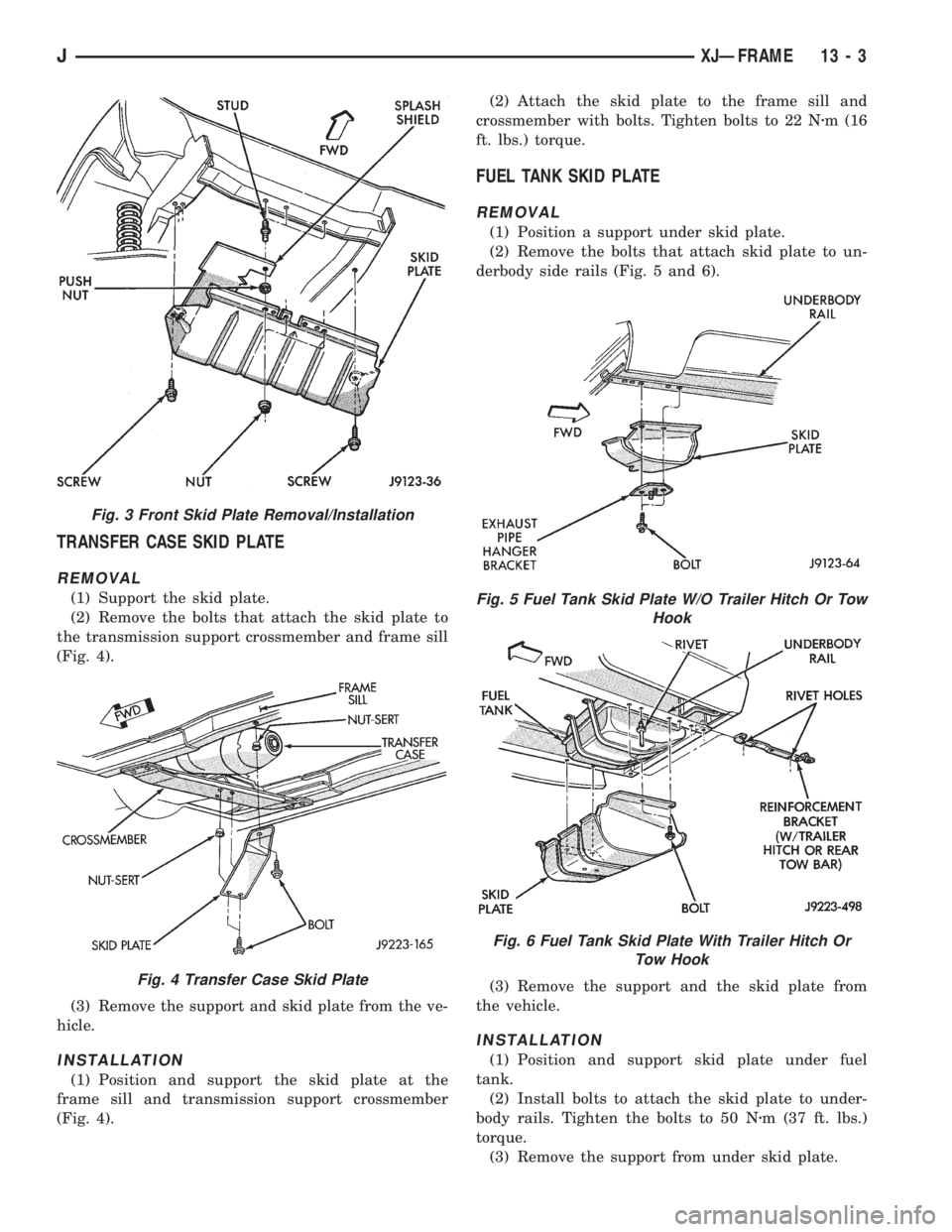
(2) Remove the bolts that attach the skid plate to
the transmission support crossmember and frame sill
(Fig. 4).
(3) Remove the support and skid plate from the ve-
hicle.
INSTALLATION
(1) Position and support the skid plate at the
frame sill and transmission support crossmember
(Fig. 4).(2) Attach the skid plate to the frame sill and
crossmember with bolts. Tighten bolts to 22 Nzm (16
ft. lbs.) torque.
FUEL TANK SKID PLATE
REMOVAL
(1) Position a support under skid plate.
(2) Remove the bolts that attach skid plate to un-
derbody side rails (Fig. 5 and 6).
(3) Remove the support and the skid plate from
the vehicle.
INSTALLATION
(1) Position and support skid plate under fuel
tank.
(2) Install bolts to attach the skid plate to under-
body rails. Tighten the bolts to 50 Nzm (37 ft. lbs.)
torque.
(3) Remove the support from under skid plate.
Fig. 3 Front Skid Plate Removal/Installation
Fig. 4 Transfer Case Skid Plate
Fig. 5 Fuel Tank Skid Plate W/O Trailer Hitch Or Tow
Hook
Fig. 6 Fuel Tank Skid Plate With Trailer Hitch Or
Tow Hook
JXJÐFRAME 13 - 3
Page 1400 of 2158
INSTALLATION
(1) Position the generator splash shield at the fan
shroud and frame rails.
(2) Force the serrated retainers into the fan shroud
holes.
(3) Force the serrated retainers into the frame rail
holes at each side of the vehicle.
TRANSFER CASE SKID PLATE
REMOVAL
(1) Raise and support the transmission.
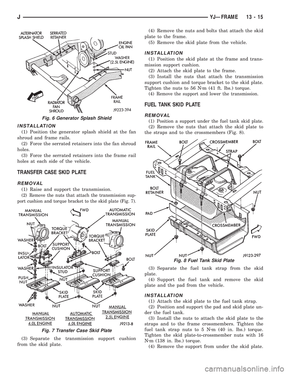
(2) Remove the nuts that attach the transmission sup-
port cushion and torque bracket to the skid plate (Fig. 7).
(3) Separate the transmission support cushion
from the skid plate.(4) Remove the nuts and bolts that attach the skid
plate to the frame.
(5) Remove the skid plate from the vehicle.
INSTALLATION
(1) Position the skid plate at the frame and trans-
mission support cushion.
(2) Attach the skid plate to the frame.
(3) Install the nuts that attach the transmission
support cushion and torque bracket to the skid plate.
Tighten the nuts to 56 Nzm (41 ft. lbs.) torque.
(4) Remove the support and lower the transmission.
FUEL TANK SKID PLATE
REMOVAL
(1) Position a support under the fuel tank skid plate.
(2) Remove the nuts that attach the skid plate to
the straps and to the crossmembers (Fig. 8).
(3) Separate the fuel tank strap from the skid
plate.
(4) Support the fuel tank and remove the skid
plate and the pad from the vehicle.
INSTALLATION
(1) Attach the skid plate to the fuel tank strap.
(2) Position and support the pad and skid plate un-
der the fuel tank.
(3) Install the nuts to attach the skid plate to the
straps and to the frame crossmembers. Tighten the
fuel tank strap nuts to 5 Nzm (40 in. lbs.) torque.
Tighten the skid plate-to-crossmember nuts with 16
Nzm (138 in. lbs.) torque.
(4) Remove the support from under the skid plate.
Fig. 6 Generator Splash Shield
Fig. 7 Transfer Case Skid Plate
Fig. 8 Fuel Tank Skid Plate
JYJÐFRAME 13 - 15
Page 1416 of 2158
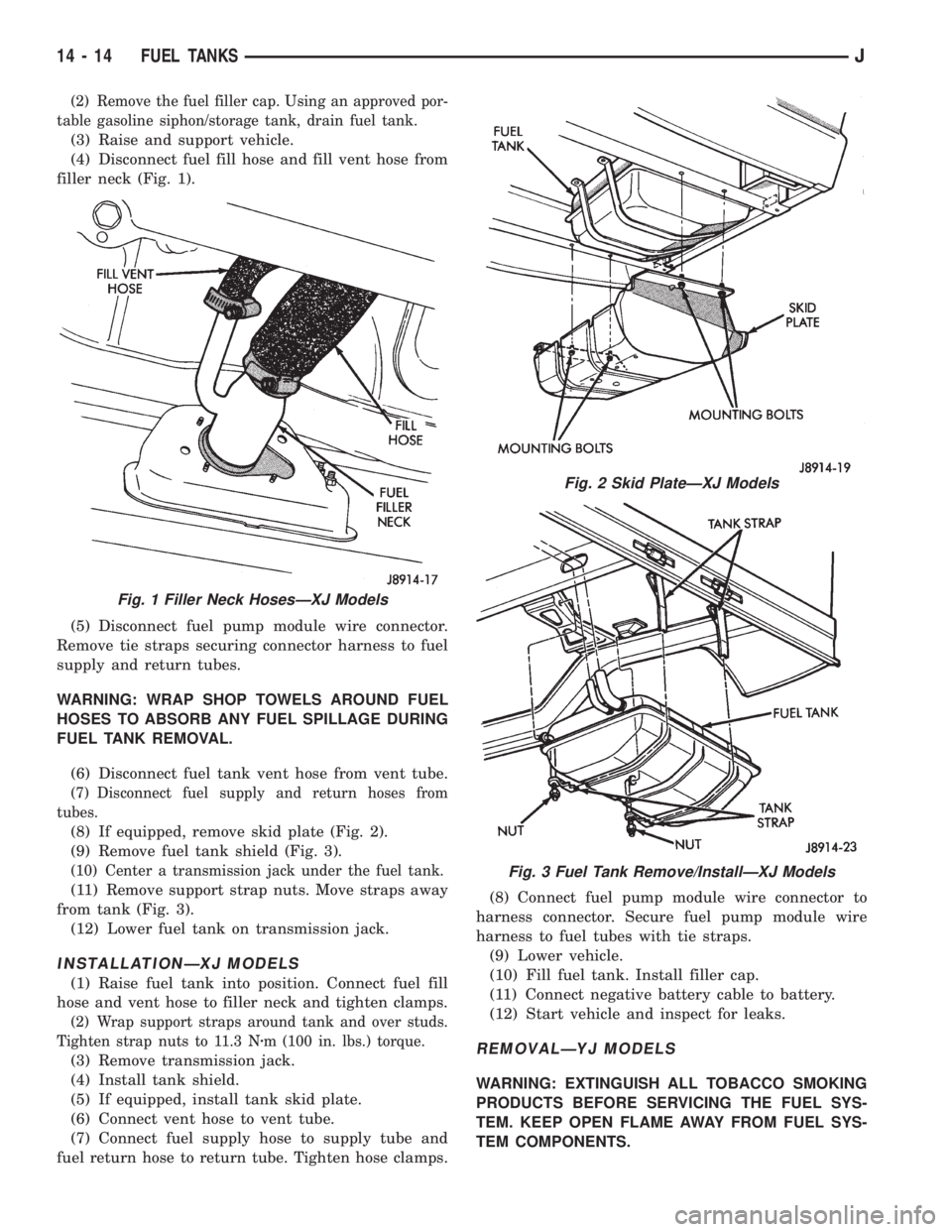
(2) Remove the fuel filler cap. Using an approved por-
table gasoline siphon/storage tank, drain fuel tank.
(3) Raise and support vehicle.
(4) Disconnect fuel fill hose and fill vent hose from
filler neck (Fig. 1).
(5) Disconnect fuel pump module wire connector.
Remove tie straps securing connector harness to fuel
supply and return tubes.
WARNING: WRAP SHOP TOWELS AROUND FUEL
HOSES TO ABSORB ANY FUEL SPILLAGE DURING
FUEL TANK REMOVAL.
(6) Disconnect fuel tank vent hose from vent tube.
(7) Disconnect fuel supply and return hoses from
tubes.
(8) If equipped, remove skid plate (Fig. 2).
(9) Remove fuel tank shield (Fig. 3).
(10) Center a transmission jack under the fuel tank.
(11) Remove support strap nuts. Move straps away
from tank (Fig. 3).
(12) Lower fuel tank on transmission jack.
INSTALLATIONÐXJ MODELS
(1) Raise fuel tank into position. Connect fuel fill
hose and vent hose to filler neck and tighten clamps.
(2) Wrap support straps around tank and over studs.
Tighten strap nuts to 11.3 Nzm (100 in. lbs.) torque.
(3) Remove transmission jack.
(4) Install tank shield.
(5) If equipped, install tank skid plate.
(6) Connect vent hose to vent tube.
(7) Connect fuel supply hose to supply tube and
fuel return hose to return tube. Tighten hose clamps.(8) Connect fuel pump module wire connector to
harness connector. Secure fuel pump module wire
harness to fuel tubes with tie straps.
(9) Lower vehicle.
(10) Fill fuel tank. Install filler cap.
(11) Connect negative battery cable to battery.
(12) Start vehicle and inspect for leaks.REMOVALÐYJ MODELS
WARNING: EXTINGUISH ALL TOBACCO SMOKING
PRODUCTS BEFORE SERVICING THE FUEL SYS-
TEM. KEEP OPEN FLAME AWAY FROM FUEL SYS-
TEM COMPONENTS.
Fig. 1 Filler Neck HosesÐXJ Models
Fig. 2 Skid PlateÐXJ Models
Fig. 3 Fuel Tank Remove/InstallÐXJ Models
14 - 14 FUEL TANKSJ
Page 1417 of 2158
(1) Disconnect negative battery cable.
(2) Remove the fuel filler cap. Using an approved
portable gasoline siphon/storage tank, drain fuel
tank.
(3) Raise and support vehicle.
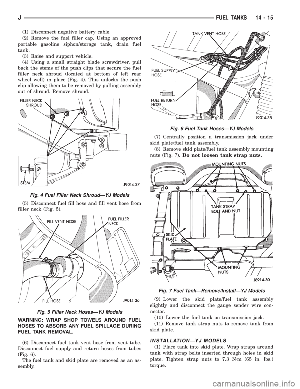
(4) Using a small straight blade screwdriver, pull
back the stems of the push clips that secure the fuel
filler neck shroud (located at bottom of left rear
wheel well) in place (Fig. 4). This unlocks the push
clip allowing them to be removed by pulling assembly
out of shroud. Remove shroud.
(5) Disconnect fuel fill hose and fill vent hose from
filler neck (Fig. 5).
WARNING: WRAP SHOP TOWELS AROUND FUEL
HOSES TO ABSORB ANY FUEL SPILLAGE DURING
FUEL TANK REMOVAL.
(6) Disconnect fuel tank vent hose from vent tube.
Disconnect fuel supply and return hoses from tubes
(Fig. 6).
The fuel tank and skid plate are removed as an as-
sembly.(7) Centrally position a transmission jack under
skid plate/fuel tank assembly.
(8) Remove skid plate/fuel tank assembly mounting
nuts (Fig. 7).Do not loosen tank strap nuts.
(9) Lower the skid plate/fuel tank assembly
slightly and disconnect the gauge sender wire con-
nector.
(10) Lower the fuel tank on transmission jack.
(11) Remove tank strap nuts to remove tank from
skid plate.
INSTALLATIONÐYJ MODELS
(1) Place tank into skid plate. Wrap straps around
tank with strap bolts inserted through holes in skid
plate. Tighten strap nuts to 7.3 Nzm (65 in. lbs.)
torque.
Fig. 4 Fuel Filler Neck ShroudÐYJ Models
Fig. 5 Filler Neck HosesÐYJ Models
Fig. 6 Fuel Tank HosesÐYJ Models
Fig. 7 Fuel TankÐRemove/InstallÐYJ Models
JFUEL TANKS 14 - 15
Page 1418 of 2158
(2) Raise skid plate/fuel tank until gauge sender
wire connector can be connected to harness connec-
tor.
(3) Finish raising skid plate/fuel tank assembly
into position. Tighten mounting nuts to 16 Nzm (12
ft. lbs.) torque. Remove transmission jack.
(4) Connect fuel fill hose and fill vent hose to filler
neck. Tighten hose clamps.
(5) Connect vent hose to vent tube.
(6) Connect fuel supply hose to the supply tube
and fuel return hose to return tube. Tighten hose
clamps.
(7) Install fuel filler neck shroud with push clips.
(8) Lower vehicle.
(9) Fill fuel tank. Install filler cap.
(10) Connect negative battery cable to battery.
(11) Start vehicle and inspect for leaks.
FUEL GAUGE SENDING UNIT
The fuel gauge sending unit is attached to the fuel
pump module. Refer to Fuel Pump Module in the
Fuel Delivery System section of this group.
FUEL TANK PRESSURE RELIEF/ROLLOVER VALVE
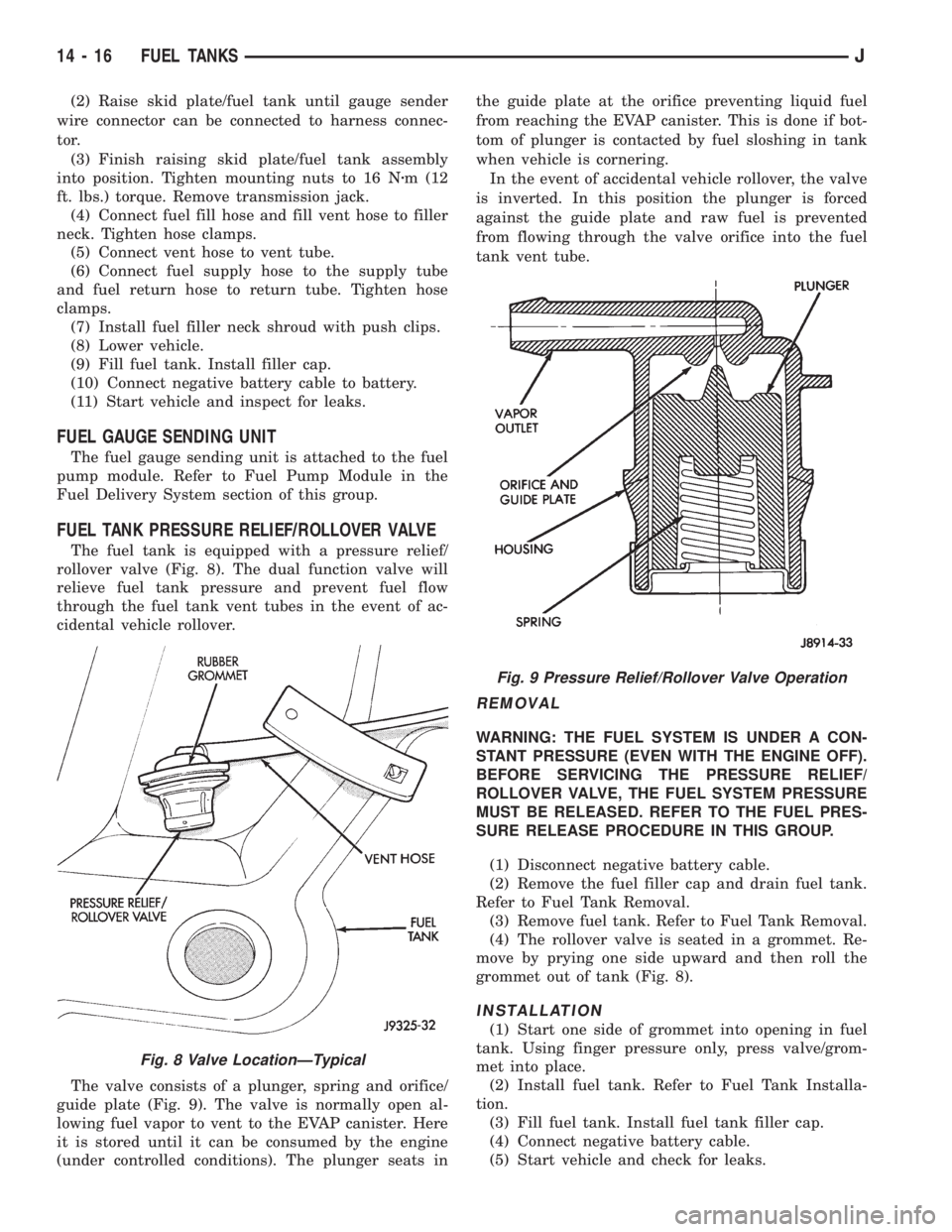
The fuel tank is equipped with a pressure relief/
rollover valve (Fig. 8). The dual function valve will
relieve fuel tank pressure and prevent fuel flow
through the fuel tank vent tubes in the event of ac-
cidental vehicle rollover.
The valve consists of a plunger, spring and orifice/
guide plate (Fig. 9). The valve is normally open al-
lowing fuel vapor to vent to the EVAP canister. Here
it is stored until it can be consumed by the engine
(under controlled conditions). The plunger seats inthe guide plate at the orifice preventing liquid fuel
from reaching the EVAP canister. This is done if bot-
tom of plunger is contacted by fuel sloshing in tank
when vehicle is cornering.
In the event of accidental vehicle rollover, the valve
is inverted. In this position the plunger is forced
against the guide plate and raw fuel is prevented
from flowing through the valve orifice into the fuel
tank vent tube.
REMOVAL
WARNING: THE FUEL SYSTEM IS UNDER A CON-
STANT PRESSURE (EVEN WITH THE ENGINE OFF).
BEFORE SERVICING THE PRESSURE RELIEF/
ROLLOVER VALVE, THE FUEL SYSTEM PRESSURE
MUST BE RELEASED. REFER TO THE FUEL PRES-
SURE RELEASE PROCEDURE IN THIS GROUP.
(1) Disconnect negative battery cable.
(2) Remove the fuel filler cap and drain fuel tank.
Refer to Fuel Tank Removal.
(3) Remove fuel tank. Refer to Fuel Tank Removal.
(4) The rollover valve is seated in a grommet. Re-
move by prying one side upward and then roll the
grommet out of tank (Fig. 8).
INSTALLATION
(1) Start one side of grommet into opening in fuel
tank. Using finger pressure only, press valve/grom-
met into place.
(2) Install fuel tank. Refer to Fuel Tank Installa-
tion.
(3) Fill fuel tank. Install fuel tank filler cap.
(4) Connect negative battery cable.
(5) Start vehicle and check for leaks.
Fig. 8 Valve LocationÐTypical
Fig. 9 Pressure Relief/Rollover Valve Operation
14 - 16 FUEL TANKSJ
Page 1421 of 2158
MULTI-PORT FUEL INJECTION (MFI)ÐCOMPONENT DESCRIPTION/SYSTEM
OPERATION
INDEX
page page
Air Cleaner.............................. 29
Air Conditioning (A/C) Clutch RelayÐPCM Output . 26
Air Conditioning (A/C) ControlsÐPCM Input...... 21
Auto Shutdown (ASD) RelayÐPCM Output...... 26
Automatic Shutdown (ASD) SenseÐPCM Input . . . 21
Battery VoltageÐPCM Input................. 21
Brake SwitchÐPCM Input................... 22
Camshaft Position SensorÐPCM Input......... 22
Crankshaft Position SensorÐPCM Input........ 22
Data Link ConnectorÐPCM Input............. 22
Data Link ConnectorÐPCM Output............ 27
EMR LampÐPCM Output................... 27
Engine Coolant Temperature SensorÐPCM Input . 23
Extended Idle SwitchÐPCM Input............. 23
Fuel InjectorsÐPCM Output................. 27
Fuel Pressure Regulator.................... 33
Fuel Pump RelayÐPCM Output.............. 27
Fuel Rail................................ 33
General Information....................... 19
Generator FieldÐPCM Output................ 27
Generator LampÐPCM Output............... 27
Idle Air Control (IAC) MotorÐPCM Output....... 27
Ignition Circuit SenseÐPCM Input............. 23
Ignition CoilÐPCM Output................... 28Intake Manifold Air Temperature SensorÐ
PCM Input............................. 22
Malfunction Indicator LampÐPCM Output....... 28
Manifold Absolute Pressure (MAP) SensorÐPCM
Input................................. 23
Open Loop/Closed Loop Modes of Operation..... 30
Oxygen (O2S) SensorÐPCM Input............ 24
Park/Neutral SwitchÐPCM Input.............. 24
Power Ground........................... 24
Power Steering Pressure SwitchÐPCM Input.... 24
Powertrain Control Module (PCM)............. 20
Radiator Fan RelayÐPCM Output............. 28
SCI ReceiveÐPCM Input................... 24
SCI TransmitÐPCM Output.................. 29
Sensor ReturnÐPCM Input.................. 25
Shift IndicatorÐPCM Output................. 29
Speed ControlÐPCM Input.................. 25
Speed ControlÐPCM Output................. 29
TachometerÐPCM Output................... 29
Throttle Body............................ 33
Throttle Position Sensor (TPS)ÐPCM Input...... 25
Torque Converter Clutch RelayÐPCM Output.... 29
Vehicle Speed SensorÐPCM Input............ 25
GENERAL INFORMATION
All 2.5L 4-cylinder and 4.0L 6-cylinder engines are
equipped with sequential Multi-Port Fuel Injection
(MFI). The MFI system provides precise air/fuel ra-
tios for all driving conditions.
The Powertrain Control Module (PCM) operates
the fuel system. The PCM was formerly referred to
as the SBEC or engine controller. The PCM is a pre-
programmed, dual microprocessor digital computer. It
regulates ignition timing, air-fuel ratio, emission con-
trol devices, charging system, speed control, air con-
ditioning compressor clutch engagement and idle
speed. The PCM can adapt its programming to meet
changing operating conditions.
Powertrain Control Module (PCM) Inputsrep-
resent the instantaneous engine operating conditions.
Air-fuel mixture and ignition timing calibrations for
various driving and atmospheric conditions are pre-
programmed into the PCM. The PCM monitors and
analyzes various inputs. It then computes engine fuel
and ignition timing requirements based on these in-
puts. Fuel delivery control and ignition timing will
then be adjusted accordingly.
Other inputs to the PCM are provided by the brake
light switch, air conditioning select switch and the
speed control switches. All inputs to the PCM are
converted into signals.
Electrically operated fuel injectors spray fuel inprecise metered amounts into the intake port directly
above the intake valve. The injectors are fired in a
specific sequence by the PCM. The PCM maintains
an air/fuel ratio of 14.7 to 1 by constantly adjusting
injector pulse width. Injector pulse width is the
length of time that the injector opens and sprays fuel
into the chamber. The PCM adjusts injector pulse
width by opening and closing the ground path to the
injector.
Manifold absolute pressure (air density) and engine
rpm (speed) are the primary inputs that determine
fuel injector pulse width. The PCM also monitors
other inputs when adjusting air-fuel ratio.
Inputs That Effect Fuel Injector Pulse Width:
²Exhaust gas oxygen content
²Engine coolant temperature
²Manifold absolute pressure (MAP)
²Engine speed
²Throttle position
²Battery voltage
²Air conditioning selection
²Transmission gear selection (automatic transmis-
sions only)
²Speed control
The powertrain control module (PCM) adjusts igni-
tion timing by controlling ignition coil operation. The
ignition coil receives battery voltage when the igni-
tion key is in the run or starter position. The PCM
JFUEL SYSTEM COMPONENT DESCRIPTION/SYSTEM OPERATION 14 - 19