1995 JEEP YJ transmission
[x] Cancel search: transmissionPage 1470 of 2158
PROPELLER SHAFTS
CONTENTS
page page
GENERAL INFORMATION.................. 1
SERVICE DIAGNOSIS..................... 3
SERVICE PROCEDURES................... 8TORQUE SPECIFICATIONS................ 15
UNIVERSAL JOINT REPLACEMENT......... 10
GENERAL INFORMATION
PROPELLER SHAFTS
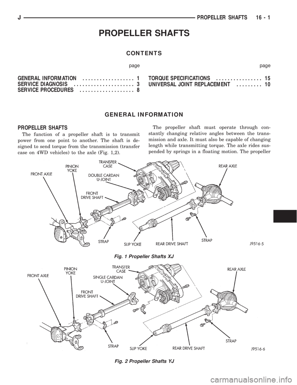
The function of a propeller shaft is to transmit
power from one point to another. The shaft is de-
signed to send torque from the transmission (transfer
case on 4WD vehicles) to the axle (Fig. 1,2).The propeller shaft must operate through con-
stantly changing relative angles between the trans-
mission and axle. It must also be capable of changing
length while transmitting torque. The axle rides sus-
pended by springs in a floating motion. The propeller
Fig. 1 Propeller Shafts XJ
Fig. 2 Propeller Shafts YJ
JPROPELLER SHAFTS 16 - 1
Page 1474 of 2158
²Have at least a 1/2 degree continuous operating
(propeller shaft) angle
Engine speed (R.P.M.) is the main factor though in
determining maximum allowable operating angles.
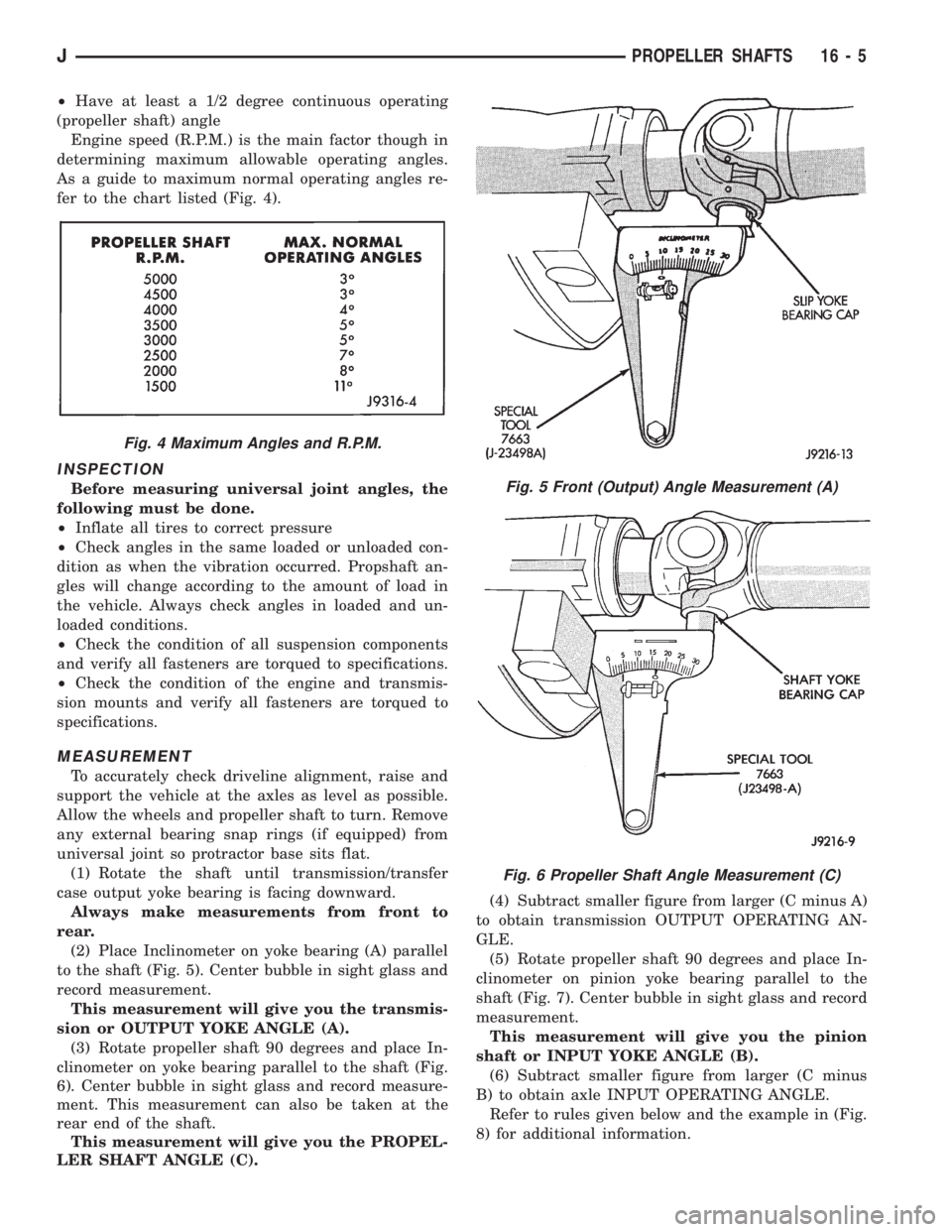
As a guide to maximum normal operating angles re-
fer to the chart listed (Fig. 4).
INSPECTION
Before measuring universal joint angles, the
following must be done.
²Inflate all tires to correct pressure
²Check angles in the same loaded or unloaded con-
dition as when the vibration occurred. Propshaft an-
gles will change according to the amount of load in
the vehicle. Always check angles in loaded and un-
loaded conditions.
²Check the condition of all suspension components
and verify all fasteners are torqued to specifications.
²Check the condition of the engine and transmis-
sion mounts and verify all fasteners are torqued to
specifications.
MEASUREMENT
To accurately check driveline alignment, raise and
support the vehicle at the axles as level as possible.
Allow the wheels and propeller shaft to turn. Remove
any external bearing snap rings (if equipped) from
universal joint so protractor base sits flat.
(1) Rotate the shaft until transmission/transfer
case output yoke bearing is facing downward.
Always make measurements from front to
rear.
(2) Place Inclinometer on yoke bearing (A) parallel
to the shaft (Fig. 5). Center bubble in sight glass and
record measurement.
This measurement will give you the transmis-
sion or OUTPUT YOKE ANGLE (A).
(3) Rotate propeller shaft 90 degrees and place In-
clinometer on yoke bearing parallel to the shaft (Fig.
6). Center bubble in sight glass and record measure-
ment. This measurement can also be taken at the
rear end of the shaft.
This measurement will give you the PROPEL-
LER SHAFT ANGLE (C).(4) Subtract smaller figure from larger (C minus A)
to obtain transmission OUTPUT OPERATING AN-
GLE.
(5) Rotate propeller shaft 90 degrees and place In-
clinometer on pinion yoke bearing parallel to the
shaft (Fig. 7). Center bubble in sight glass and record
measurement.
This measurement will give you the pinion
shaft or INPUT YOKE ANGLE (B).
(6) Subtract smaller figure from larger (C minus
B) to obtain axle INPUT OPERATING ANGLE.
Refer to rules given below and the example in (Fig.
8) for additional information.
Fig. 4 Maximum Angles and R.P.M.
Fig. 5 Front (Output) Angle Measurement (A)
Fig. 6 Propeller Shaft Angle Measurement (C)
JPROPELLER SHAFTS 16 - 5
Page 1477 of 2158
SERVICE PROCEDURES
PRECAUTIONS
Use exact replacement hardware for attaching the
propeller shafts. Exact replacement will ensure safe
operation. The specified torque must always be ap-
plied when tightening the fasteners.
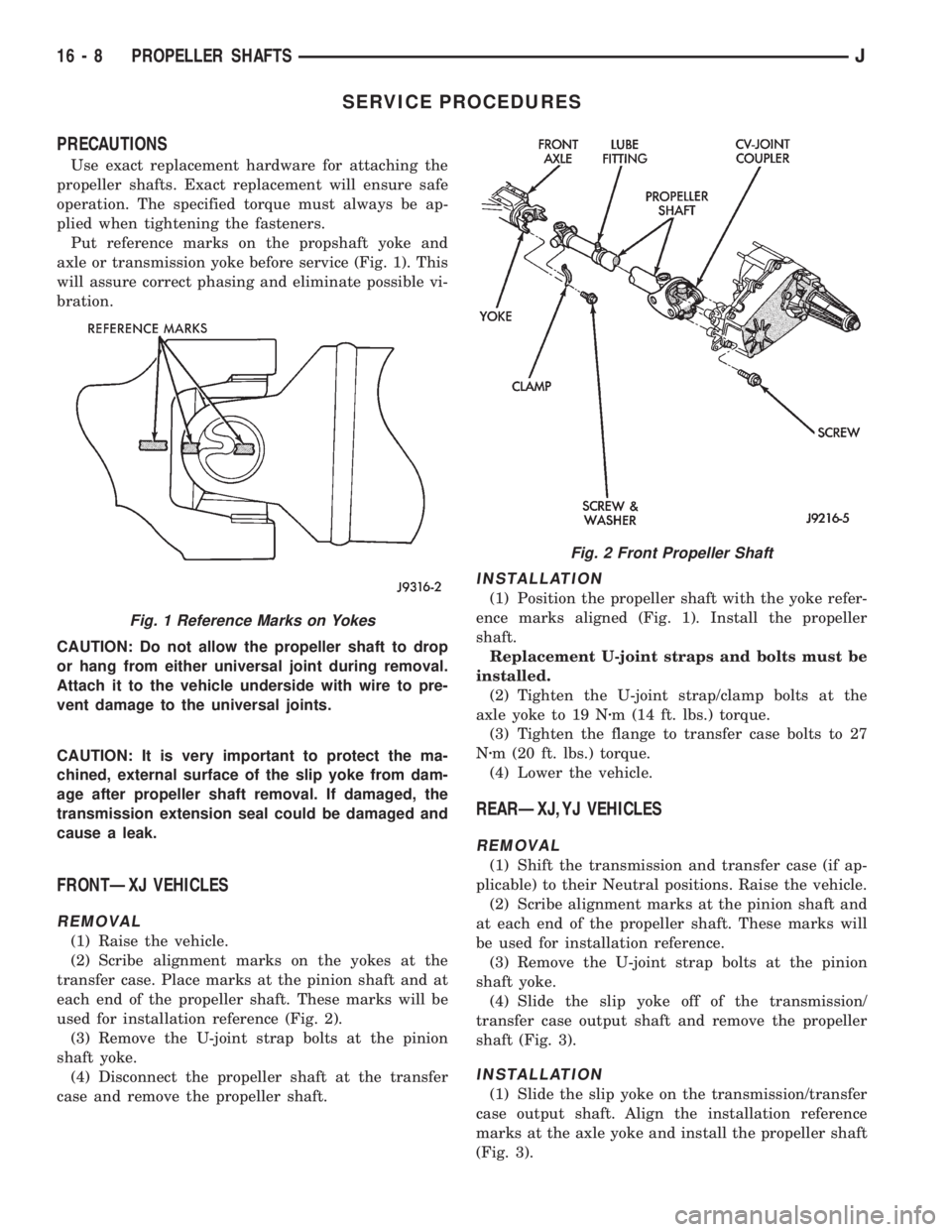
Put reference marks on the propshaft yoke and
axle or transmission yoke before service (Fig. 1). This
will assure correct phasing and eliminate possible vi-
bration.
CAUTION: Do not allow the propeller shaft to drop
or hang from either universal joint during removal.
Attach it to the vehicle underside with wire to pre-
vent damage to the universal joints.
CAUTION: It is very important to protect the ma-
chined, external surface of the slip yoke from dam-
age after propeller shaft removal. If damaged, the
transmission extension seal could be damaged and
cause a leak.
FRONTÐXJ VEHICLES
REMOVAL
(1) Raise the vehicle.
(2) Scribe alignment marks on the yokes at the
transfer case. Place marks at the pinion shaft and at
each end of the propeller shaft. These marks will be
used for installation reference (Fig. 2).
(3) Remove the U-joint strap bolts at the pinion
shaft yoke.
(4) Disconnect the propeller shaft at the transfer
case and remove the propeller shaft.
INSTALLATION
(1) Position the propeller shaft with the yoke refer-
ence marks aligned (Fig. 1). Install the propeller
shaft.
Replacement U-joint straps and bolts must be
installed.
(2) Tighten the U-joint strap/clamp bolts at the
axle yoke to 19 Nzm (14 ft. lbs.) torque.
(3) Tighten the flange to transfer case bolts to 27
Nzm (20 ft. lbs.) torque.
(4) Lower the vehicle.
REARÐXJ,YJ VEHICLES
REMOVAL
(1) Shift the transmission and transfer case (if ap-
plicable) to their Neutral positions. Raise the vehicle.
(2) Scribe alignment marks at the pinion shaft and
at each end of the propeller shaft. These marks will
be used for installation reference.
(3) Remove the U-joint strap bolts at the pinion
shaft yoke.
(4) Slide the slip yoke off of the transmission/
transfer case output shaft and remove the propeller
shaft (Fig. 3).
INSTALLATION
(1) Slide the slip yoke on the transmission/transfer
case output shaft. Align the installation reference
marks at the axle yoke and install the propeller shaft
(Fig. 3).
Fig. 1 Reference Marks on Yokes
Fig. 2 Front Propeller Shaft
16 - 8 PROPELLER SHAFTSJ
Page 1486 of 2158
POWER STEERING PUMP
Hydraulic pressure is provided for operation of the
power steering gear by a belt driven power steering
pump. The power steering pump is a constant flow
rate and displacement, vane-type pump. The internal
parts in the housing operate submerged in fluid. The
flow control orifice is part of the high pressure line
fitting. The pressure relief valve inside the flow con-
trol valve limits the pump pressure.
Power steering pumps have different pres-
sure rates and are not interchangeable with
other pumps.
The power steering pump is connected to the steer-
ing gear via high pressure and return hose. The
pump shaft has a pressed-on drive pulley that is belt
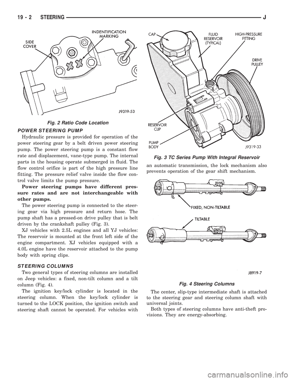
driven by the crankshaft pulley (Fig. 3).
XJ vehicles with 2.5L engines and all YJ vehicles:
The reservoir is mounted at the front left side of the
engine compartment. XJ vehicles equipped with a
4.0L engine have the reservoir attached to the pump
body with spring clips.
STEERING COLUMNS
Two general types of steering columns are installed
on Jeep vehicles: a fixed, non-tilt column and a tilt
column (Fig. 4).
The ignition key/lock cylinder is located in the
steering column. When the key/lock cylinder is
turned to the LOCK position, the ignition switch and
steering shaft cannot be operated. For vehicles withan automatic transmission, the lock mechanism also
prevents operation of the gear shift mechanism.
The center, slip-type intermediate shaft is attached
to the steering gear and steering column shaft with
universal joints.
Both types of steering columns have anti-theft pro-
visions. They are energy-absorbing.
Fig. 2 Ratio Code Location
Fig. 3 TC Series Pump With Integral Reservoir
Fig. 4 Steering Columns
19 - 2 STEERINGJ
Page 1499 of 2158
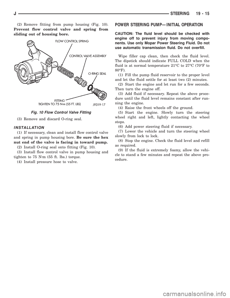
(2) Remove fitting from pump housing (Fig. 10).
Prevent flow control valve and spring from
sliding out of housing bore.
(3) Remove and discard O-ring seal.
INSTALLATION
(1) If necessary, clean and install flow control valve
and spring in pump housing bore.Be sure the hex
nut end of the valve is facing in toward pump.
(2) Install O-ring seal onto fitting (Fig. 10).
(3) Install flow control valve in pump housing and
tighten to 75 Nzm (55 ft. lbs.) torque.
(4) Install pressure hose to valve.
POWER STEERING PUMPÐINITIAL OPERATION
CAUTION: The fluid level should be checked with
engine off to prevent injury from moving compo-
nents. Use only Mopar Power Steering Fluid. Do not
use automatic transmission fluid. Do not overfill.
Wipe filler cap clean, then check the fluid level.
The dipstick should indicate FULL COLD when the
fluid is at normal temperature 21ÉC to 27ÉC (70ÉF to
80ÉF).
(1) Fill the pump fluid reservoir to the proper level
and let the fluid settle for at least two (2) minutes.
(2) Start the engine and let run for a few seconds.
Then turn the engine off.
(3) Add fluid if necessary. Repeat the above proce-
dure until the fluid level remains constant after run-
ning the engine.
(4) Raise the front wheels off the ground.
(5) Start the engine. Slowly turn the steering
wheel right and left, lightly contacting the wheel
stops.
(6) Add power steering fluid if necessary.
(7) Lower the vehicle and turn the steering wheel
slowly from lock to lock.
(8) Stop the engine. Check the fluid level and refill
as required.
(9) If the fluid is extremely foamy, allow the vehi-
cle to stand a few minutes and repeat the above pro-
cedure.
Fig. 10 Flow Control Valve Fitting
JSTEERING 19 - 15
Page 1537 of 2158
(14) Remove the Interlock cable from the steering
column. Refer to Automatic Transmission Shifter/Ig-
nition Interlock in this group.
(15) Remove the column. Use care to avoid damag-
ing the paint or trim.
INSTALLATION
CAUTION: Bumping, jolting and hammering on the
steering column shaft and gear shift tube must be
avoided during all service procedures.
(1) With the front wheels in the straight ahead po-
sition. Align and install the column to coupler.Do
not apply force at the top of the steering col-
umn shaft.(2) Ensure the ground clip is on the left spacer slot
(Fig. 17).
(3) Install the Interlock cable from the steering col-
umn. Refer to Automatic Transmission Shifter/Igni-
tion Interlock in this group.
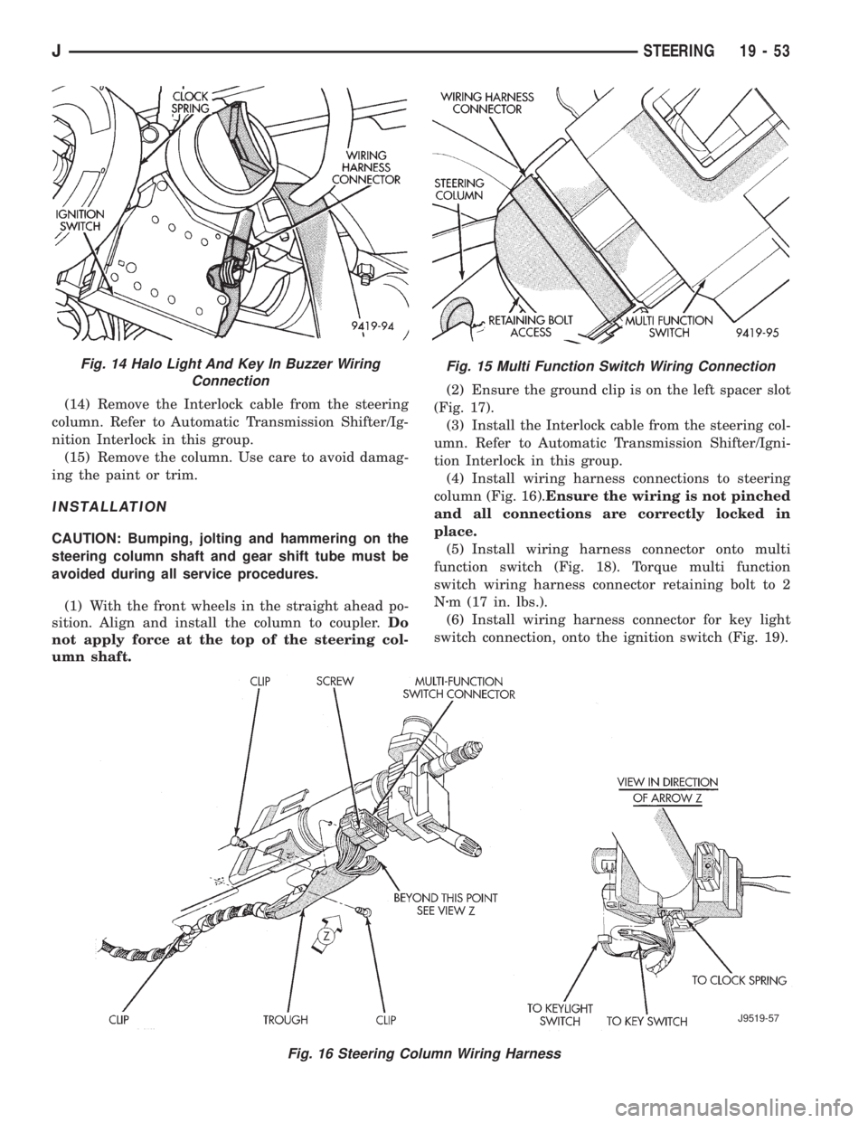
(4) Install wiring harness connections to steering
column (Fig. 16).Ensure the wiring is not pinched
and all connections are correctly locked in
place.
(5) Install wiring harness connector onto multi
function switch (Fig. 18). Torque multi function
switch wiring harness connector retaining bolt to 2
Nzm (17 in. lbs.).
(6) Install wiring harness connector for key light
switch connection, onto the ignition switch (Fig. 19).
Fig. 15 Multi Function Switch Wiring Connection
Fig. 16 Steering Column Wiring Harness
J9519-57
Fig. 14 Halo Light And Key In Buzzer Wiring
Connection
JSTEERING 19 - 53
Page 1539 of 2158
(1) Remove the ignition switch from the steering
column. Refer toGroup 8D Ignition System.
(2) Using a key cylinder, check the turning effort of
the switch.
²If the ignition switch binds look for the following
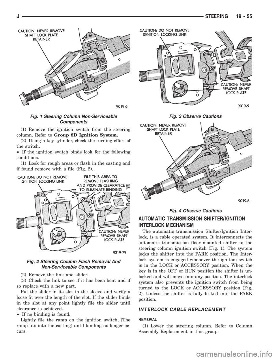
conditions.
(1) Look for rough areas or flash in the casting and
if found remove with a file (Fig. 2).
(2) Remove the link and slider.
(3) Check the link to see if it has been bent and if
so replace with a new part.
Put the slider in its slot in the sleeve and verify a
loose fit over the length of the slot. If the slider binds
in the slot at any point lightly file the slider until
clearance is achieved.
²If no binding is found.
Lightly file the ramp on the ignition switch, (The
ramp fits into the casting) until binding no longer oc-
curs.
AUTOMATIC TRANSMISSION SHIFTER/IGNITION
INTERLOCK MECHANISM
The automatic transmission Shifter/Ignition Inter-
lock, is a cable operated system. It interconnects the
automatic transmission floor mounted shifter to the
steering column ignition switch (Fig. 1). The system
locks the shifter into the PARK position. The Inter-
lock system is engaged whenever the ignition switch
is in the LOCK or ACCESSORY position. When the
key is in the OFF or RUN position the shifter is un-
locked and will move into any position. The interlock
system also prevents the ignition switch from being
turned to the LOCK or ACCESSORY position (Fig.
2). Unless the shifter is fully locked into the PARK
position.
INTERLOCK CABLE REPLACEMENT
REMOVAL
(1) Lower the steering column. Refer to Column
Assembly Replacement in this group.
Fig. 1 Steering Column Non-Serviceable
Components
Fig. 2 Steering Column Flash Removal And
Non-Serviceable Components
Fig. 3 Observe Cautions
Fig. 4 Observe Cautions
JSTEERING 19 - 55
Page 1541 of 2158
(3) Place the ignition key cylinder in the ACCES-
SORY position.
(4) Remove shipping pin from plastic base.
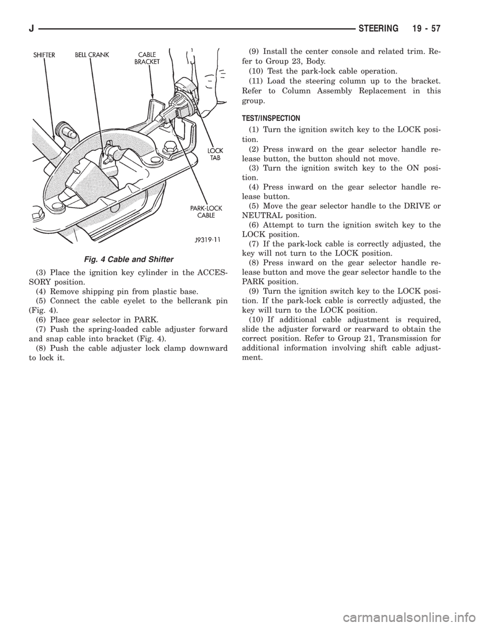
(5) Connect the cable eyelet to the bellcrank pin
(Fig. 4).
(6) Place gear selector in PARK.
(7) Push the spring-loaded cable adjuster forward
and snap cable into bracket (Fig. 4).
(8) Push the cable adjuster lock clamp downward
to lock it.(9) Install the center console and related trim. Re-
fer to Group 23, Body.
(10) Test the park-lock cable operation.
(11) Load the steering column up to the bracket.
Refer to Column Assembly Replacement in this
group.
TEST/INSPECTION
(1) Turn the ignition switch key to the LOCK posi-
tion.
(2) Press inward on the gear selector handle re-
lease button, the button should not move.
(3) Turn the ignition switch key to the ON posi-
tion.
(4) Press inward on the gear selector handle re-
lease button.
(5) Move the gear selector handle to the DRIVE or
NEUTRAL position.
(6) Attempt to turn the ignition switch key to the
LOCK position.
(7) If the park-lock cable is correctly adjusted, the
key will not turn to the LOCK position.
(8) Press inward on the gear selector handle re-
lease button and move the gear selector handle to the
PARK position.
(9) Turn the ignition switch key to the LOCK posi-
tion. If the park-lock cable is correctly adjusted, the
key will turn to the LOCK position.
(10) If additional cable adjustment is required,
slide the adjuster forward or rearward to obtain the
correct position. Refer to Group 21, Transmission for
additional information involving shift cable adjust-
ment.
Fig. 4 Cable and Shifter
JSTEERING 19 - 57