1995 JEEP YJ manual transmission
[x] Cancel search: manual transmissionPage 1658 of 2158
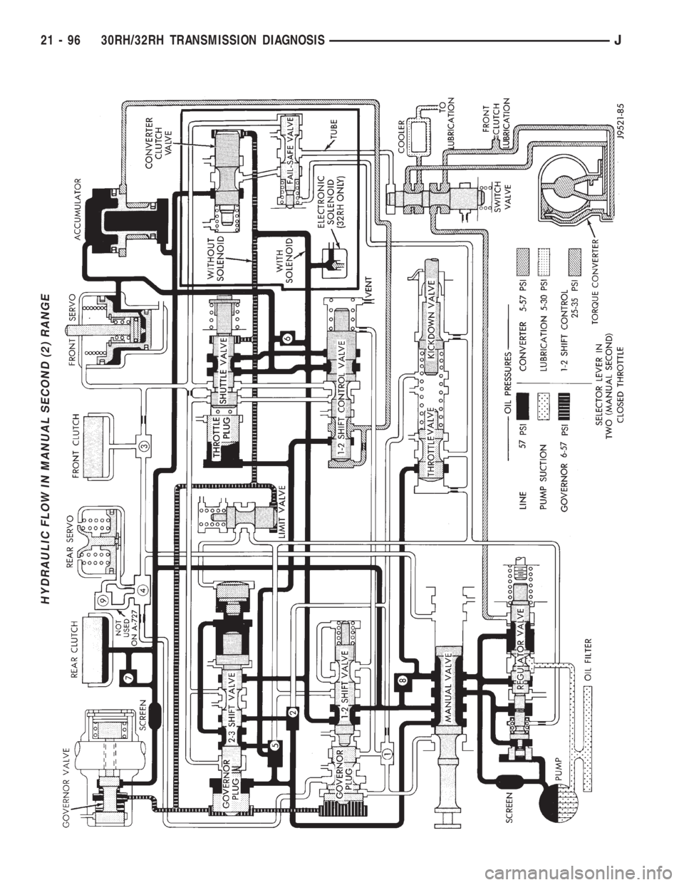
HYDRAULIC FLOW IN MANUAL SECOND (2) RANGE
21 - 96 30RH/32RH TRANSMISSION DIAGNOSISJ
Page 1659 of 2158
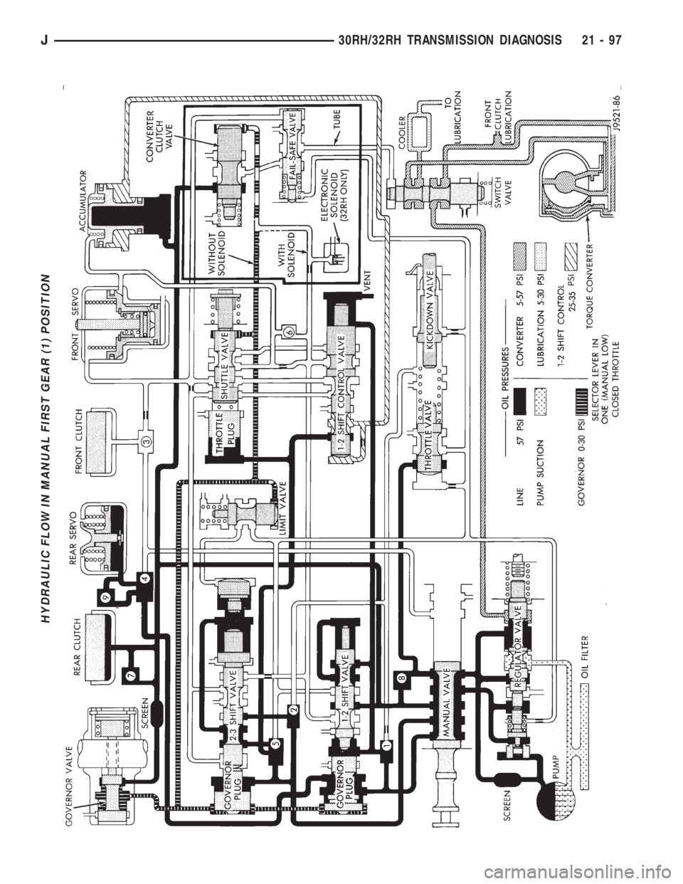
HYDRAULIC FLOW IN MANUAL FIRST GEAR (1) POSITION
J30RH/32RH TRANSMISSION DIAGNOSIS 21 - 97
Page 1662 of 2158
(c) Vehicle is used for trailer towing or heavy
load hauling.
FLUID/FILTER REPLACEMENT PROCEDURE
(1) Raise vehicle.
(2) Remove oil pan and drain fluid.
(3) Clean oil pan and pan magnet. Then clean re-
maining gasket material from gasket surface of
transmission case.
(4) Remove fluid filter screws and remove filter.
(5) Position new filter on valve body and install fil-
ter screws. Tighten screws to 4 Nzm (35 in. lbs.)
torque.
(6) Adjust rear band at this time if required.
(7) Position new gasket on oil pan and install pan
on transmission. Tighten pan bolts to 150 in. lbs. (17
Nzm) torque.
(8) Adjust front band at this time if required.
(9) Lower vehicle and refill transmission with Mo-
par ATF Plus, type 7176 fluid.
REFILLING AFTER OVERHAUL OR FLUID/FILTER
CHANGE
The most effective way to avoid overfilling after a
fluid change or overhaul is as follows:
(1) Remove dipstick and insert clean funnel in
transmission fill tube.
(2) Add following initial quantity of Mopar ATF
Plus to transmission:
(a) If only fluid and filter were changed, add3
pints (1-1/2 quarts)of ATF Plus to transmission.
(b) If transmission was completely overhauled
and torque converter was replaced or drained, add
10 pints (5 quarts)of ATF Plus to transmission.
(3) Apply parking brakes.
(4) Start and run engine at normal curb idle speed.
(5) Apply service brakes, shift transmission
through all gear ranges then back to Neutral, and
leave engine running at curb idle speed.
(6) Remove funnel, insert dipstick and check fluid
level. Add only enough fluid to bring level toMIN
dot mark on dipstick.
(7) Drive vehicle until transmission fluid is at nor-
mal operating temperature. Then recheck fluid level
as described in next step.
(8) Leave engine running at curb idle speed, shift
into Neutral, and check fluid level again. This time,
add just enough fluid to bring level up toMAX ar-
row mark but do not overfill.
(9) When fluid level is correct, shut engine off, re-
lease park brake, remove funnel, and reseat dipstick
in fill tube.
SHIFT LINKAGE ADJUSTMENT (YJ)
(1) Check linkage adjustment by starting engine in
Park and Neutral.(2) Adjustment is OK if engine starts only in park
and Neutral. Adjustment is incorrect if engine starts
in one but not both positions.
(3) If engine starts in any position other than Park
or Neutral, or if engine will not start at all, park/
neutral position switch may be faulty.
(4) Shift transmission into Park.
(5) Raise vehicle.
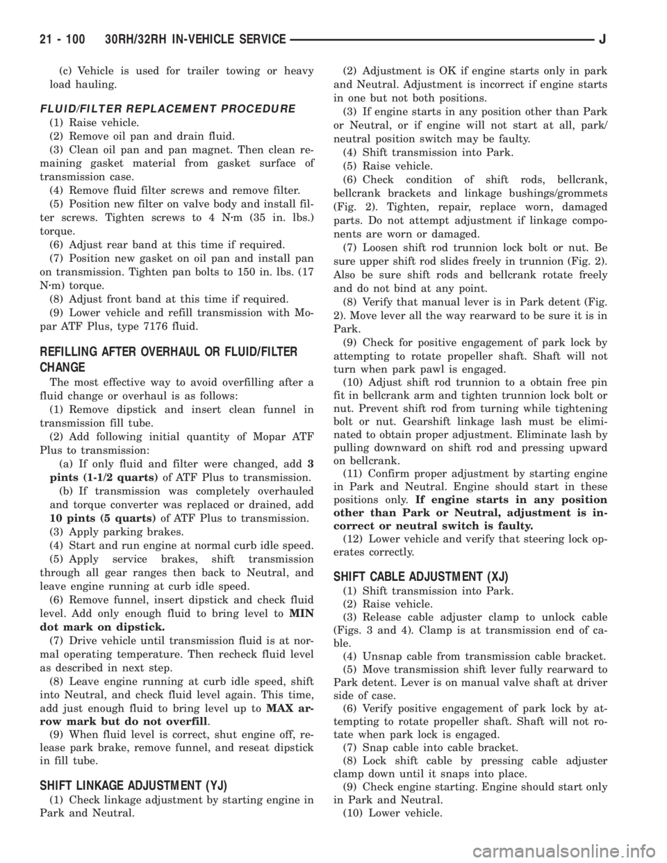
(6) Check condition of shift rods, bellcrank,
bellcrank brackets and linkage bushings/grommets
(Fig. 2). Tighten, repair, replace worn, damaged
parts. Do not attempt adjustment if linkage compo-
nents are worn or damaged.
(7) Loosen shift rod trunnion lock bolt or nut. Be
sure upper shift rod slides freely in trunnion (Fig. 2).
Also be sure shift rods and bellcrank rotate freely
and do not bind at any point.
(8) Verify that manual lever is in Park detent (Fig.
2). Move lever all the way rearward to be sure it is in
Park.
(9) Check for positive engagement of park lock by
attempting to rotate propeller shaft. Shaft will not
turn when park pawl is engaged.
(10) Adjust shift rod trunnion to a obtain free pin
fit in bellcrank arm and tighten trunnion lock bolt or
nut. Prevent shift rod from turning while tightening
bolt or nut. Gearshift linkage lash must be elimi-
nated to obtain proper adjustment. Eliminate lash by
pulling downward on shift rod and pressing upward
on bellcrank.
(11) Confirm proper adjustment by starting engine
in Park and Neutral. Engine should start in these
positions only.If engine starts in any position
other than Park or Neutral, adjustment is in-
correct or neutral switch is faulty.
(12) Lower vehicle and verify that steering lock op-
erates correctly.
SHIFT CABLE ADJUSTMENT (XJ)
(1) Shift transmission into Park.
(2) Raise vehicle.
(3) Release cable adjuster clamp to unlock cable
(Figs. 3 and 4). Clamp is at transmission end of ca-
ble.
(4) Unsnap cable from transmission cable bracket.
(5) Move transmission shift lever fully rearward to
Park detent. Lever is on manual valve shaft at driver
side of case.
(6) Verify positive engagement of park lock by at-
tempting to rotate propeller shaft. Shaft will not ro-
tate when park lock is engaged.
(7) Snap cable into cable bracket.
(8) Lock shift cable by pressing cable adjuster
clamp down until it snaps into place.
(9) Check engine starting. Engine should start only
in Park and Neutral.
(10) Lower vehicle.
21 - 100 30RH/32RH IN-VEHICLE SERVICEJ
Page 1664 of 2158
THROTTLE VALVE CABLE ADJUSTMENT
PROCEDURE
Cable adjustment is performed entirely in the
engine compartment. It is not necessary to
raise the vehicle for access to any other compo-
nents.
(1) Shift transmission into Park and shut engine
off.
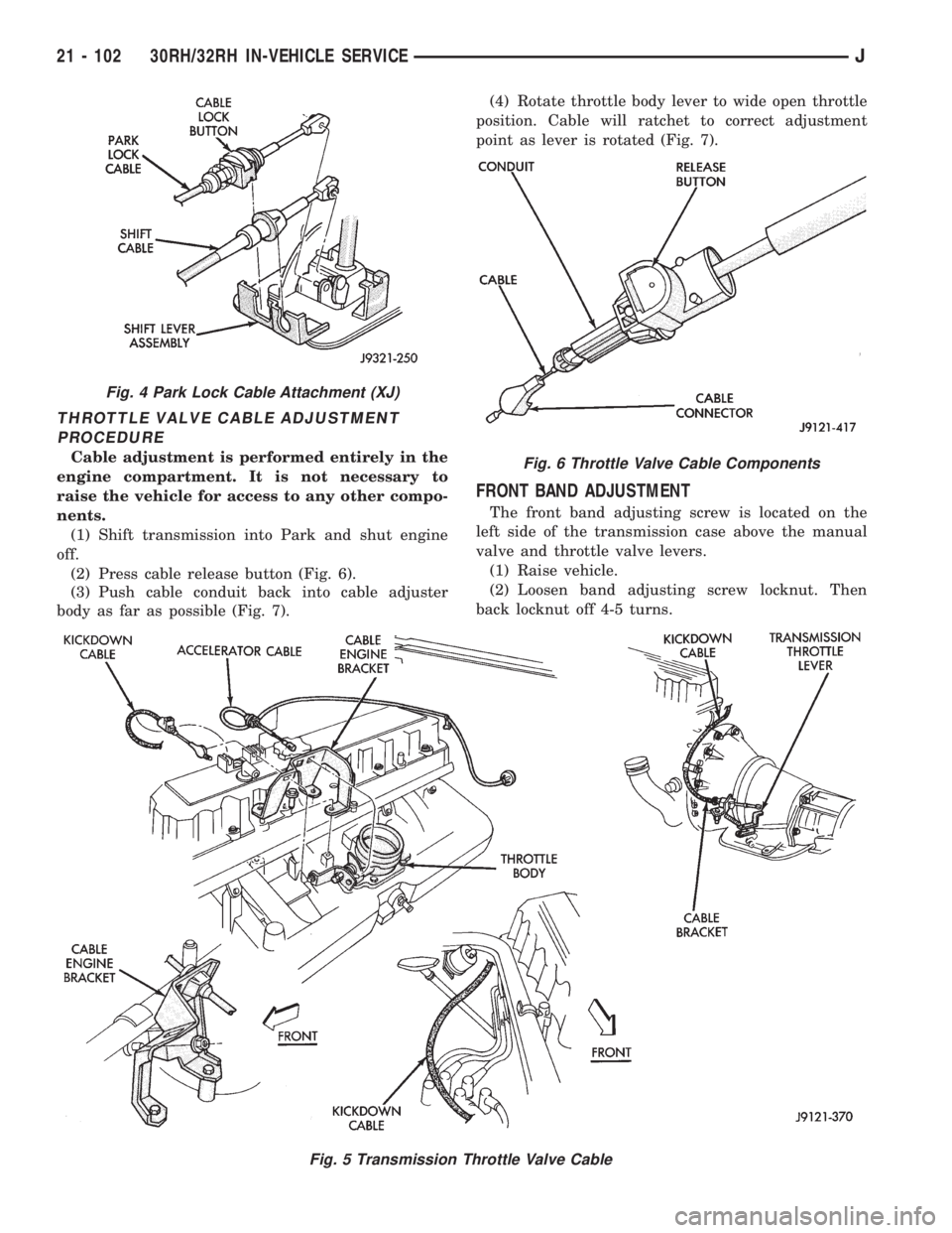
(2) Press cable release button (Fig. 6).
(3) Push cable conduit back into cable adjuster
body as far as possible (Fig. 7).(4) Rotate throttle body lever to wide open throttle
position. Cable will ratchet to correct adjustment
point as lever is rotated (Fig. 7).
FRONT BAND ADJUSTMENT
The front band adjusting screw is located on the
left side of the transmission case above the manual
valve and throttle valve levers.
(1) Raise vehicle.
(2) Loosen band adjusting screw locknut. Then
back locknut off 4-5 turns.
Fig. 5 Transmission Throttle Valve Cable
Fig. 4 Park Lock Cable Attachment (XJ)
Fig. 6 Throttle Valve Cable Components
21 - 102 30RH/32RH IN-VEHICLE SERVICEJ
Page 1666 of 2158
on transmission. Tighten pan bolts to 17 Nzm (150 in.
lbs.) torque.
(7) Lower vehicle.
(8) Refill transmission with Mopar ATF Plus.
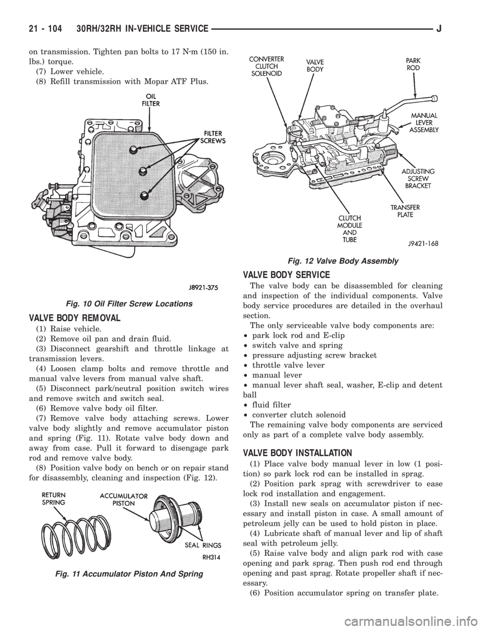
VALVE BODY REMOVAL
(1) Raise vehicle.
(2) Remove oil pan and drain fluid.
(3) Disconnect gearshift and throttle linkage at
transmission levers.
(4) Loosen clamp bolts and remove throttle and
manual valve levers from manual valve shaft.
(5) Disconnect park/neutral position switch wires
and remove switch and switch seal.
(6) Remove valve body oil filter.
(7) Remove valve body attaching screws. Lower
valve body slightly and remove accumulator piston
and spring (Fig. 11). Rotate valve body down and
away from case. Pull it forward to disengage park
rod and remove valve body.
(8) Position valve body on bench or on repair stand
for disassembly, cleaning and inspection (Fig. 12).
VALVE BODY SERVICE
The valve body can be disassembled for cleaning
and inspection of the individual components. Valve
body service procedures are detailed in the overhaul
section.
The only serviceable valve body components are:
²park lock rod and E-clip
²switch valve and spring
²pressure adjusting screw bracket
²throttle valve lever
²manual lever
²manual lever shaft seal, washer, E-clip and detent
ball
²fluid filter
²converter clutch solenoid
The remaining valve body components are serviced
only as part of a complete valve body assembly.
VALVE BODY INSTALLATION
(1) Place valve body manual lever in low (1 posi-
tion) so park lock rod can be installed in sprag.
(2) Position park sprag with screwdriver to ease
lock rod installation and engagement.
(3) Install new seals on accumulator piston if nec-
essary and install piston in case. A small amount of
petroleum jelly can be used to hold piston in place.
(4) Lubricate shaft of manual lever and lip of shaft
seal with petroleum jelly.
(5) Raise valve body and align park rod with case
opening and park sprag. Then push rod end through
opening and past sprag. Rotate propeller shaft if nec-
essary.
(6) Position accumulator spring on transfer plate.
Fig. 10 Oil Filter Screw Locations
Fig. 11 Accumulator Piston And Spring
Fig. 12 Valve Body Assembly
21 - 104 30RH/32RH IN-VEHICLE SERVICEJ
Page 1667 of 2158
(7) Align valve body and seat it on case. Be sure
manual lever shaft and accumulator spring are prop-
erly seated.
(8) Hold valve body in position and install one or
two attaching bolts to hold valve body in place.
(9) Install remaining valve body bolts. Tighten all
bolts evenly in a diagonal pattern to 12 Nzm (105 in-
lbs) torque.
(10) Install new oil filter and tighten filter screws
to4Nzm (35 in. lbs.) torque.
(11) Connect converter solenoid wire to case con-
nector.
(12) Install manual and throttle levers on throttle
lever shaft. Tighten lever clamp screws and check for
free operation. Shaft and levers must operate freely
without any bind.
(13) Install oil pan and new gasket. Tighten pan
bolts to 17 Nzm (13 ft. lbs.) torque.
(14) Install seal on neutral switch, install switch in
case, and connect switch wires.
(15) Lower vehicle.
(16) Fill transmission with Mopar ATF Plus, Type
7176 fluid.
(17) Adjust gearshift linkage and throttle valve
(kickdown) cable if necessary.
GOVERNOR AND PARK GEAR SERVICE
GOVERNOR/PARK GEAR REMOVAL
(1) Raise vehicle.
(2) Mark both propeller shaft yokes for assembly
reference and disconnect propeller shafts at transfer
case.
(3) Disconnect speed sensor wires and remove
speedometer adapter and sensor.
(4) Position support stand under transmission con-
verter housing.
(5) Remove rear crossmember.
(6) Disconnect parking brake cable at equalizer
and disconnect exhaust components as necessary.
(7) Support transfer case with jack.
(8) Remove bolts attaching transfer case to trans-
mission adapter housing and remove transfer case.
(9) Remove bolts attaching adapter, or extension
housing to transmission and remove adapter/housing.
(10) Loosen but do not remove bolts that attach
governor body to park gear.
(11) Rotate transmission output shaft until gover-
nor weight assembly is accessible. Then remove
E-clip at this end of governor shaft.
(12) Remove governor valve and shaft from gover-
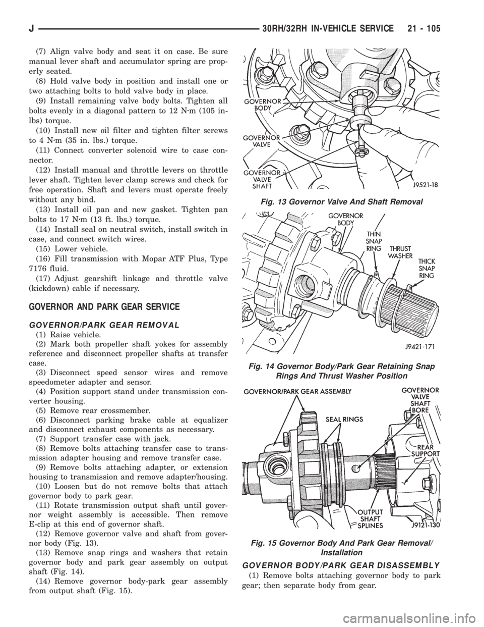
nor body (Fig. 13).
(13) Remove snap rings and washers that retain
governor body and park gear assembly on output
shaft (Fig. 14).
(14) Remove governor body-park gear assembly
from output shaft (Fig. 15).
GOVERNOR BODY/PARK GEAR DISASSEMBLY
(1) Remove bolts attaching governor body to park
gear; then separate body from gear.
Fig. 13 Governor Valve And Shaft Removal
Fig. 14 Governor Body/Park Gear Retaining Snap
Rings And Thrust Washer Position
Fig. 15 Governor Body And Park Gear Removal/
Installation
J30RH/32RH IN-VEHICLE SERVICE 21 - 105
Page 1671 of 2158
Inspection
Check the sprag shaft for scores and for free move-
ment in the housing and sprag.
Check the sprag and control rod springs for loss of
tension or distortion. Check the square lug on the
sprag for broken edges. Check the lugs on the gover-
nor support (park gear) for broken edges. Replace
any park lock components that are worn or damaged.
Check the knob on the end of the control rod for
nicks, burrs and free turning. Replace the rod if the
knob is grooved, or worn, or if the rod is bent. The
park lock rods used in Chrysler 3-speed transmis-
sions are different lengths. If the rod must be re-
placed, be sure to install the correct length and
shape rod.
COMPONENT INSTALLATION
(1) Install park lock rod on valve body.
(2) Install reaction plug and pin assembly in the
housing and install the snap ring.
(3) Position sprag and spring in housing and in-
stall sprag shaft. Be sure square lug on sprag is fac-
ing park gear and that spring is positioned so it
moves sprag away from park gear.
(4) Install valve body.
(5) Install adapter housing and transfer case.
PARK/NEUTRAL POSITION SWITCH SERVICE
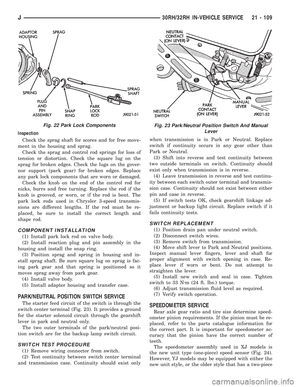
The starter feed circuit of the switch is through the
switch center terminal (Fig. 23). It provides a ground
for the starter solenoid circuit through the gearshift
lever in park and neutral only.
The two outer terminals of the park/neutral posi-
tion switch are for the backup lamp switch circuit.
SWITCH TEST PROCEDURE
(1) Remove wiring connector from switch.
(2) Test continuity between switch center terminal
and transmission case. Continuity should exist onlywhen transmission is in Park or Neutral. Replace
switch if continuity occurs in any gear other than
Park or Neutral.
(3) Shift into reverse and test continuity between
two outside terminals on switch. Continuity should
exist only when transmission is in reverse.
(4) Leave transmission in reverse and test continu-
ity between each switch outer terminal and transmis-
sion case. Continuity should not exist between either
pin and case in reverse.
(5) If switch tests OK, check gearshift linkage ad-
justment or backup light circuit. Replace switch if it
fails continuity tests.
SWITCH REPLACEMENT
(1) Position drain pan under neutral switch.
(2) Disconnect switch wires.
(3) Remove switch from transmission.
(4) Move shift lever to Park and Neutral positions.
Inspect manual lever fingers, lever and shaft for
proper alignment with switch opening in case. Re-
place lever if worn or bent. Do not attempt to
straighten the lever.
(5) Install new switch and seal in case. Tighten
switch to 33 Nzm (24 ft. lbs.) torque.
(6) Adjust transmission fluid level as required.
(7) Verify switch operation.
SPEEDOMETER SERVICE
Rear axle gear ratio and tire size determine speed-
ometer pinion requirements. If the pinion must be re-
placed, refer to the parts catalogue information for
the correct part. It is important for speedometer ac-
curacy that the pinion have the correct number of
teeth.
The speedometer assembly used in XJ models is
the new unit type (one-piece) speed sensor (Fig. 24).
However, YJ models may be equipped with either the
new unit style, or the older style that has a two-piece
Fig. 22 Park Lock ComponentsFig. 23 Park/Neutral Position Switch And Manual
Lever
J30RH/32RH IN-VEHICLE SERVICE 21 - 109
Page 1681 of 2158
30RH/32RH TRANSMISSION OVERHAUL
INDEX
page page
Adapter/Extension Housing Inspection and Park
Lock Component Overhaul................ 127
Front Clutch Overhaul..................... 134
Front Servo and Band Overhaul............. 146
Governor and Park Gear Overhaul........... 127
Oil Pump Overhaul....................... 131
Overhaul Service Information................ 125
Overrunning ClutchÐLow-Reverse DrumÐRear
Support Overhaul....................... 125
Planetary Gear Train Overhaul.............. 141Rear Clutch Overhaul..................... 138
Rear Servo and Band Overhaul.............. 146
Transmission Assembly and Adjustment Procedures. 155
Transmission Assembly Tips................ 155
Transmission Case Cleaning and Inspection.... 125
Transmission Disassembly.................. 119
Valve Body Assembly and Adjustment......... 153
Valve Body Disassembly and Inspection....... 147
TRANSMISSION DISASSEMBLY
(1) Clean transmission exterior with steam gun or
with solvent. Wear eye protection during cleaning
process.
(2) Remove throttle and shift levers from valve
body manual shaft and throttle lever shaft.
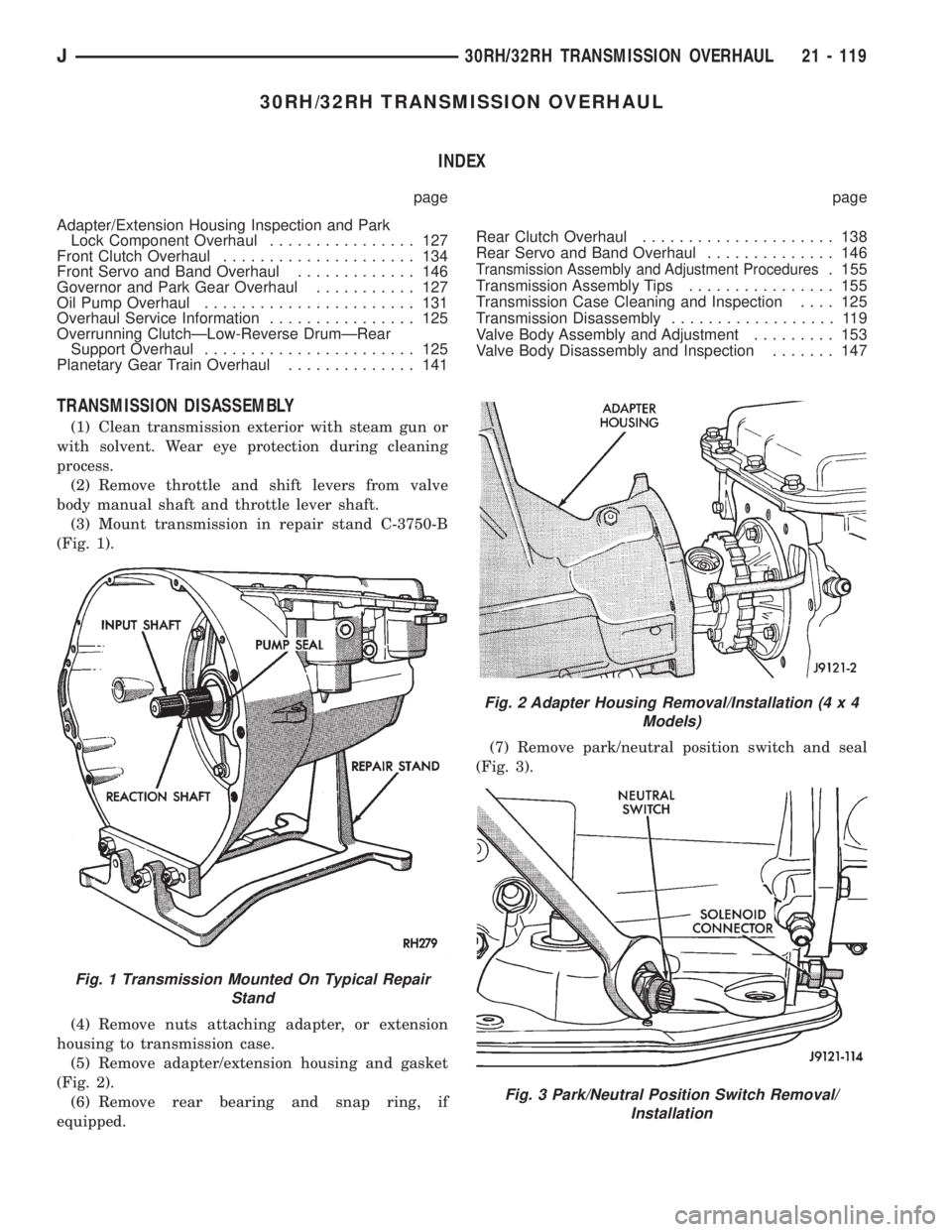
(3) Mount transmission in repair stand C-3750-B
(Fig. 1).
(4) Remove nuts attaching adapter, or extension
housing to transmission case.
(5) Remove adapter/extension housing and gasket
(Fig. 2).
(6) Remove rear bearing and snap ring, if
equipped.(7) Remove park/neutral position switch and seal
(Fig. 3).
Fig. 1 Transmission Mounted On Typical Repair
Stand
Fig. 2 Adapter Housing Removal/Installation (4 x 4
Models)
Fig. 3 Park/Neutral Position Switch Removal/
Installation
J30RH/32RH TRANSMISSION OVERHAUL 21 - 119