1995 JEEP YJ light
[x] Cancel search: lightPage 430 of 2158

lamps and repair circuits or replace bulbs as re-
quired. If system still does not function properly, pro-
ceed as follows.
(1) Locate fuseblock module under driver's side of
instrument panel. Remove and inspect fuse 4. If OK,
go to next step. If not OK, replace fuse as required.
(2) Replace turn signal flasher (light blue can in
fuseblock module) with a known good unit. Test op-
eration. If OK, replace faulty turn signal flasher. If
not OK, remove test flasher and go to next step.
(3) Turn ignition switch to ACCESSORY position.
Check for battery voltage at flasher cavity on left
(closest to hazard flasher). If OK, go to next step. If
not OK, repair circuit to fuse 4 as required.
(4) Turn ignition switch to OFF position. See Turn
Signal/Hazard Warning Switch Remove/Install to lo-
cate steering column connector. Unplug connector.
(5) Turn ignition switch to ACCESSORY position.
Check for battery voltage at connector terminal L. If
OK, replace turn signal/hazard warning switch. If not
OK, repair circuit between turn signal flasher and
steering column connector.
HAZARD WARNING SYSTEM - YJ
(1) Locate Power Distribution Center (PDC) near
battery tray in engine compartment. Remove and in-
spect fuse F5. If OK, go to next step. If not OK,
replace fuse as required.(2) Replace hazard warning flasher (metal can in
fuseblock module) with a known good unit. Test op-
eration. If OK, replace faulty hazard warning flasher.
If not OK, remove test flasher and go to next step.
(3) Check for battery voltage at flasher cavity on
left (closest to hazard flasher). If OK, go to next step.
If not OK, repair circuit to fuse F5 in PDC as re-
quired.
(4) See Turn Signal/Hazard Warning Switch Re-
move/Install to locate steering column connector. Un-
plug connector.
(5) Check for battery voltage at connector terminal
K. If OK, replace turn signal/hazard warning switch.
If not OK, repair circuit between hazard warning
flasher and steering column connector.
MULTI-FUNCTION SWITCH - XJ
(1) Access multi-function switch connector and re-
move. See service procedures for Multi-Function
Switch, in this group.
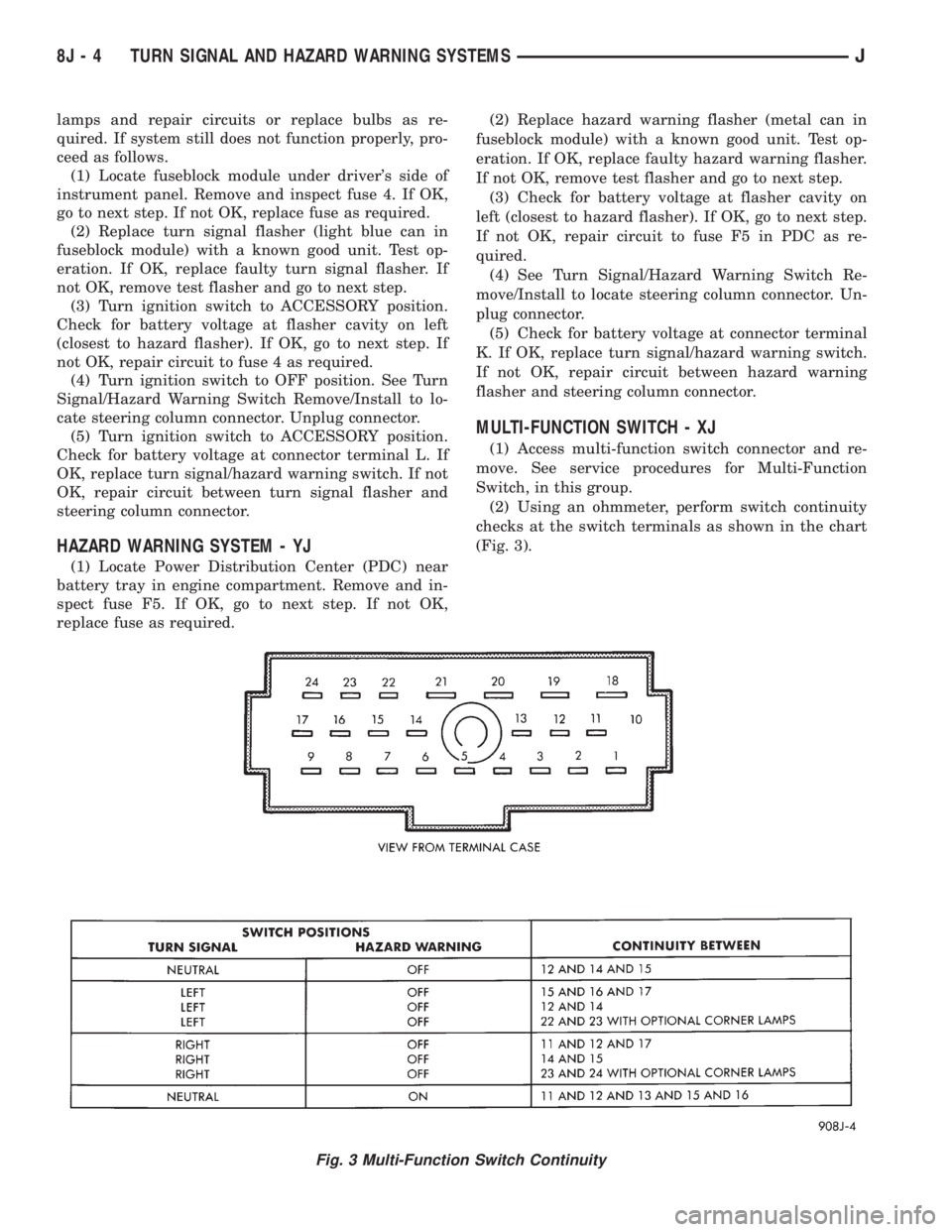
(2) Using an ohmmeter, perform switch continuity
checks at the switch terminals as shown in the chart
(Fig. 3).
Fig. 3 Multi-Function Switch Continuity
8J - 4 TURN SIGNAL AND HAZARD WARNING SYSTEMSJ
Page 442 of 2158

(12) Reverse removal procedures to install. Tighten
fasteners as follows:
²wiring connector to switch retaining screw to 2
Nzm (17 in. lbs.)
²multi-function switch to column retaining screws
to2Nzm (17 in. lbs.)
²steering column shroud retaining screws to 2 Nzm
(17 in. lbs.).
LIFTGATE WIPER/WASHER SWITCH REMOVE/
INSTALL
(1) Remove the instrument cluster bezel. Refer to
Group 8E - Instrument Panel and Gauges for proce-
dure.
(2) Remove the switch housing panel.
(3) Unplug the switch connector. Slightly depress
the switch mounting tabs and remove the switch
(Fig. 14).
(4) Reverse removal procedures to install.
WASHER PUMP/RESERVOIR REMOVE/INSTALL
LEFT-HAND DRIVE
(1) Remove 2 washer reservoir attaching screws
and 1 nut (Fig. 15).
(2) Disconnect hose(s) from washer pump(s) (Fig.
16) and drain solvent from reservoir into a clean con-
tainer for re-use.
(3) Use a deep socket and extension inserted
through the filler neck to remove washer pump filter/
nut from inside reservoir. Remove pump from reser-
voir.
(4) Reverse removal procedures to install.
RIGHT-HAND DRIVE
(1) Disconnect battery cables, negative cable first,
and remove battery.
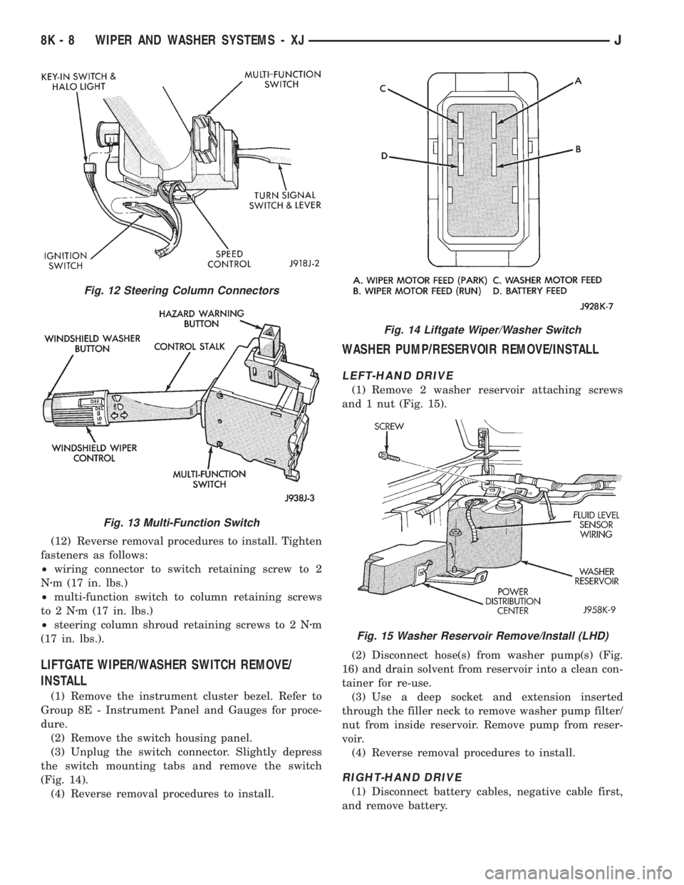
Fig. 12 Steering Column Connectors
Fig. 13 Multi-Function Switch
Fig. 14 Liftgate Wiper/Washer Switch
Fig. 15 Washer Reservoir Remove/Install (LHD)
8K - 8 WIPER AND WASHER SYSTEMS - XJJ
Page 443 of 2158

(2) Reservoir filler neck is held in reservoir by a
grommet. Remove reservoir filler neck (Fig. 17) by
pulling sharply away from reservoir.
(3) Remove 2 reservoir mounting screws.
(4) Raise vehicle on hoist and remove left front in-
ner wheelhouse splash shield.
(5) Disconnect hose(s) from washer pump(s) and
drain solvent from reservoir into a clean container
for re-use.
(6) Disconnect wiring from pump(s) and fluid level
sensor (if equipped).
(7) Remove washer pumps from reservoir by pull-
ing out of grommets.
(8) To remove reservoir, slide slightly towards rear
of vehicle to release hook (Fig. 17) from inner fender
slot. Then lower front of reservoir and slide unit for-
ward to remove.(9) Reverse removal procedures to install. Use new
grommets when installing washer pumps.
Fig. 16 Washer Pumps (LHD)
Fig. 17 Washer Reservoir and Pumps (RHD)
JWIPER AND WASHER SYSTEMS - XJ 8K - 9
Page 458 of 2158

(36) Install a new switch and switch cover.
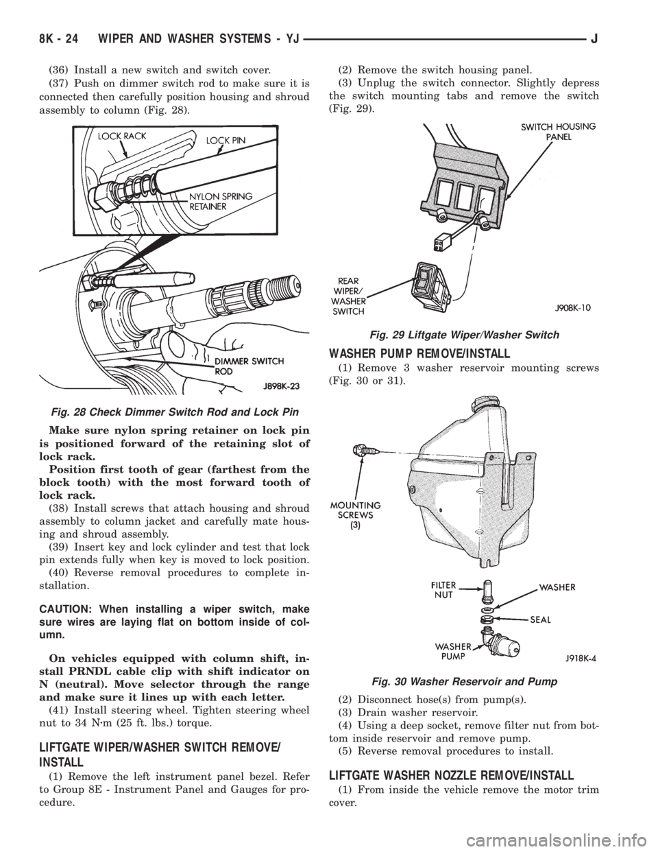
(37) Push on dimmer switch rod to make sure it is
connected then carefully position housing and shroud
assembly to column (Fig. 28).
Make sure nylon spring retainer on lock pin
is positioned forward of the retaining slot of
lock rack.
Position first tooth of gear (farthest from the
block tooth) with the most forward tooth of
lock rack.
(38) Install screws that attach housing and shroud
assembly to column jacket and carefully mate hous-
ing and shroud assembly.
(39) Insert key and lock cylinder and test that lock
pin extends fully when key is moved to lock position.
(40) Reverse removal procedures to complete in-
stallation.
CAUTION: When installing a wiper switch, make
sure wires are laying flat on bottom inside of col-
umn.
On vehicles equipped with column shift, in-
stall PRNDL cable clip with shift indicator on
N (neutral). Move selector through the range
and make sure it lines up with each letter.
(41) Install steering wheel. Tighten steering wheel
nut to 34 Nzm (25 ft. lbs.) torque.
LIFTGATE WIPER/WASHER SWITCH REMOVE/
INSTALL
(1) Remove the left instrument panel bezel. Refer
to Group 8E - Instrument Panel and Gauges for pro-
cedure.(2) Remove the switch housing panel.
(3) Unplug the switch connector. Slightly depress
the switch mounting tabs and remove the switch
(Fig. 29).
WASHER PUMP REMOVE/INSTALL
(1) Remove 3 washer reservoir mounting screws
(Fig. 30 or 31).
(2) Disconnect hose(s) from pump(s).
(3) Drain washer reservoir.
(4) Using a deep socket, remove filter nut from bot-
tom inside reservoir and remove pump.
(5) Reverse removal procedures to install.
LIFTGATE WASHER NOZZLE REMOVE/INSTALL
(1) From inside the vehicle remove the motor trim
cover.
Fig. 28 Check Dimmer Switch Rod and Lock Pin
Fig. 29 Liftgate Wiper/Washer Switch
Fig. 30 Washer Reservoir and Pump
8K - 24 WIPER AND WASHER SYSTEMS - YJJ
Page 461 of 2158

LAMPS
CONTENTS
page page
BULB APPLICATIONÐXJ VEHICLES......... 18
GENERAL INFORMATION.................. 1INTERIOR LAMPS....................... 16
SERVICE PROCEDURES................... 6
GENERAL INFORMATION
Each vehicle is equipped with various lamp assem-
blies. A good ground is necessary for proper lighting
operation. Grounding is provided by the lamp socket
when it comes in contact with the metal body, or
through a separate ground wire.
When changing lamp bulbs check the socket for
corrosion. If corrosion is present, clean it with a wire
brush and coat the inside of the socket lightly with
Mopar Multi-Purpose Grease or equivalent.
DIAGNOSTIC PROCEDURESÐXJ
When a vehicle experiences problems with the
headlamp system, verify the condition of the batteryconnections, charging system, headlamp bulbs, wire
connectors, relay, high beam dimmer switch and
headlamp switch. Refer to Group 8W, Wiring Dia-
grams for component locations and circuit informa-
tion.
Always begin any diagnosis by testing all of the
fuses and circuit breakers in the system. Refer to
Group 8W, Wiring Diagrams.
JLAMPS 8L - 1
Page 464 of 2158

MULTI-FUNCTION SWITCH TESTING
PROCEDURESÐXJ
The multi-function switch contains electrical cir-
cuitry for:
²Headlamp Dimmer Switch.
²Passing Lights.
²Turn Signals.
²Hazard Warning.
²Windshield Wiper.
²Pulse Wiper.
²Windshield Washer.
This integrated switch is mounted to the left hand
side of the steering column. Should any function of
the switch fail, the entire switch must be replaced.
The multi-function switch also serves as a fog lamp
lock-out circuit. The circuit to the fog lamp switch is
completed only when the dimmer switch is in the low
beam position.
SWITCH TEST
(1) Disconnect battery negative cable.
(2) Remove lower instrument panel screws along
bottom edge of steering column (Fig. 1).
(3) Remove lower instrument panel/knee blocker.
(4) Remove tilt lever.
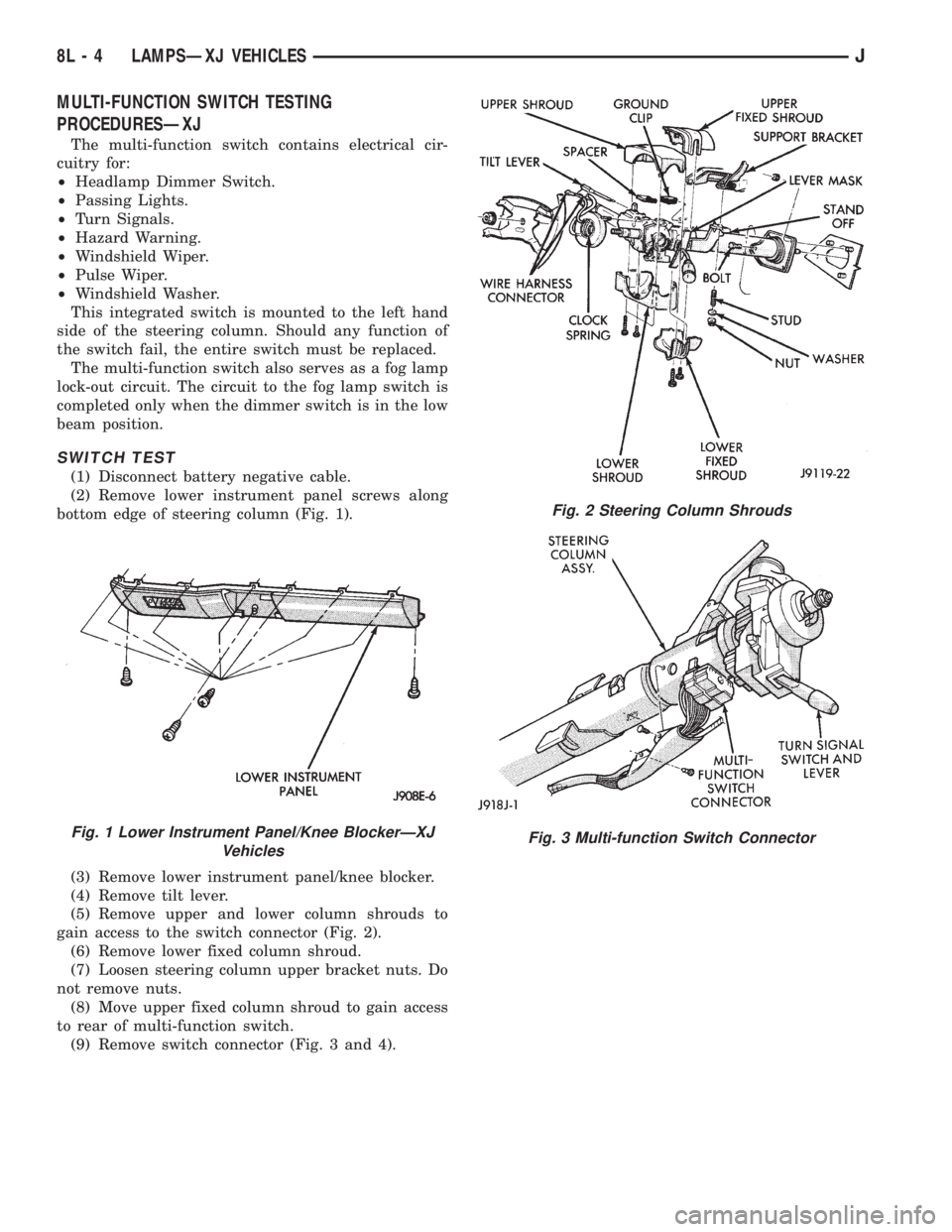
(5) Remove upper and lower column shrouds to
gain access to the switch connector (Fig. 2).
(6) Remove lower fixed column shroud.
(7) Loosen steering column upper bracket nuts. Do
not remove nuts.
(8) Move upper fixed column shroud to gain access
to rear of multi-function switch.
(9) Remove switch connector (Fig. 3 and 4).
Fig. 1 Lower Instrument Panel/Knee BlockerÐXJ
Vehicles
Fig. 2 Steering Column Shrouds
Fig. 3 Multi-function Switch Connector
8L - 4 LAMPSÐXJ VEHICLESJ
Page 466 of 2158

SERVICE PROCEDURES
INDEX
page page
Back-Up/Rear Turn Signal/Tail Lamp Bulb
ReplacementÐXJ....................... 12
Center High Mounted Stop Lamp (CHMSL)ÐXJ . . 12
Daytime Running Lights (Canada Only)ÐXJ..... 15
Drl Module ReplacementÐXJ................ 15
Fog Lamp ReplacementÐXJ.................. 9
Fog Lamp Switch ReplacementÐXJ........... 10
Fog LampsÐXJ........................... 7
Front Park/Turn Signal Lamp Bulb
ReplacementÐXJ........................ 9
Headlamp Alignment PreparationÐXJ........... 6
Headlamp AlignmentÐXJ.................... 6
Headlamp Bulb ReplacementÐXJ.............. 7Headlamp Delay Function Trouble DiagnosisÐXJ . 14
Headlamp Delay Module ReplacementÐXJ...... 14
Headlamp SwitchÐXJ...................... 10
Headlamp/Fog Lamp Adjustment Using Alignment
ScreenÐXJ............................. 7
License Plate LampÐXJ.................... 12
Multi-Function Switch Service ProceduresÐXJ.... 11
Sentinel Headlamp Delay ModuleÐXJ.......... 14
Side Marker Lamp Bulb ReplacementÐXJ....... 10
Underhood Lamp Bulb ReplacementÐXJ....... 13
Underhood Lamp ReplacementÐXJ........... 13
Underhood Lamp Service InformationÐXJ....... 12
HEADLAMP ALIGNMENTÐXJ
Headlamps can be aligned using the screen method
provided in this section. Alignment Tool C4466-A or
equivalent can also be used. Refer to instructions
provided with the tool for proper procedures.The
preferred headlamp alignment setting is 0 for
the left/right adjustment and 1(down for the
up/down adjustment.
HEADLAMP ALIGNMENT PREPARATIONÐXJ
(1) Verify headlamp dimmer switch and high beam
indicator operation.
(2) Correct defective components that could hinder
proper headlamp alignment.
(3) Verify proper tire inflation.
(4) Clean headlamp lenses.
(5) Verify that luggage area is not heavily loaded.
Fig. 1 Headlamp Alignment ScreenÐTypical
8L - 6 LAMPSÐXJ VEHICLESJ
Page 475 of 2158

DAYTIME RUNNING LIGHTS (CANADA ONLY)ÐXJ
SERVICE INFORMATION
The Daytime Running Lights (Headlamps) System
is installed on vehicles manufactured for sale in Can-
ada only. The headlamps are illuminated when the
ignition switch is turned to the ON position. The
DRL module receives a vehicle-moving signal from
the vehicle speed sensor. This provides a constant
headlamps-oncondition as long as the vehicle is
moving. The lamps are illuminated at less than 50
percent of normal intensity.
DRL MODULE REPLACEMENTÐXJ
REMOVAL
The Daytime Running Lights (DRL) module is lo-
cated on the right fender inner panel adjacent to the
dash panel (Fig. 24).
(1) Disconnect the wire harness connector from the
module.
(2) Remove the screws that attach the module to
the fender inner panel.
(3) Remove the module from the fender inner
panel.
INSTALLATION
(1) Position the module on the right fender inner
panel.
(2) Install the attaching screws. Tighten the
screws securely.(3) Connect the wire harness connector to the mod-
ule.
Fig. 24 Daytime Running Lights (DRL) Module
JLAMPSÐXJ VEHICLES 8L - 15