1995 JEEP YJ body components
[x] Cancel search: body componentsPage 1940 of 2158
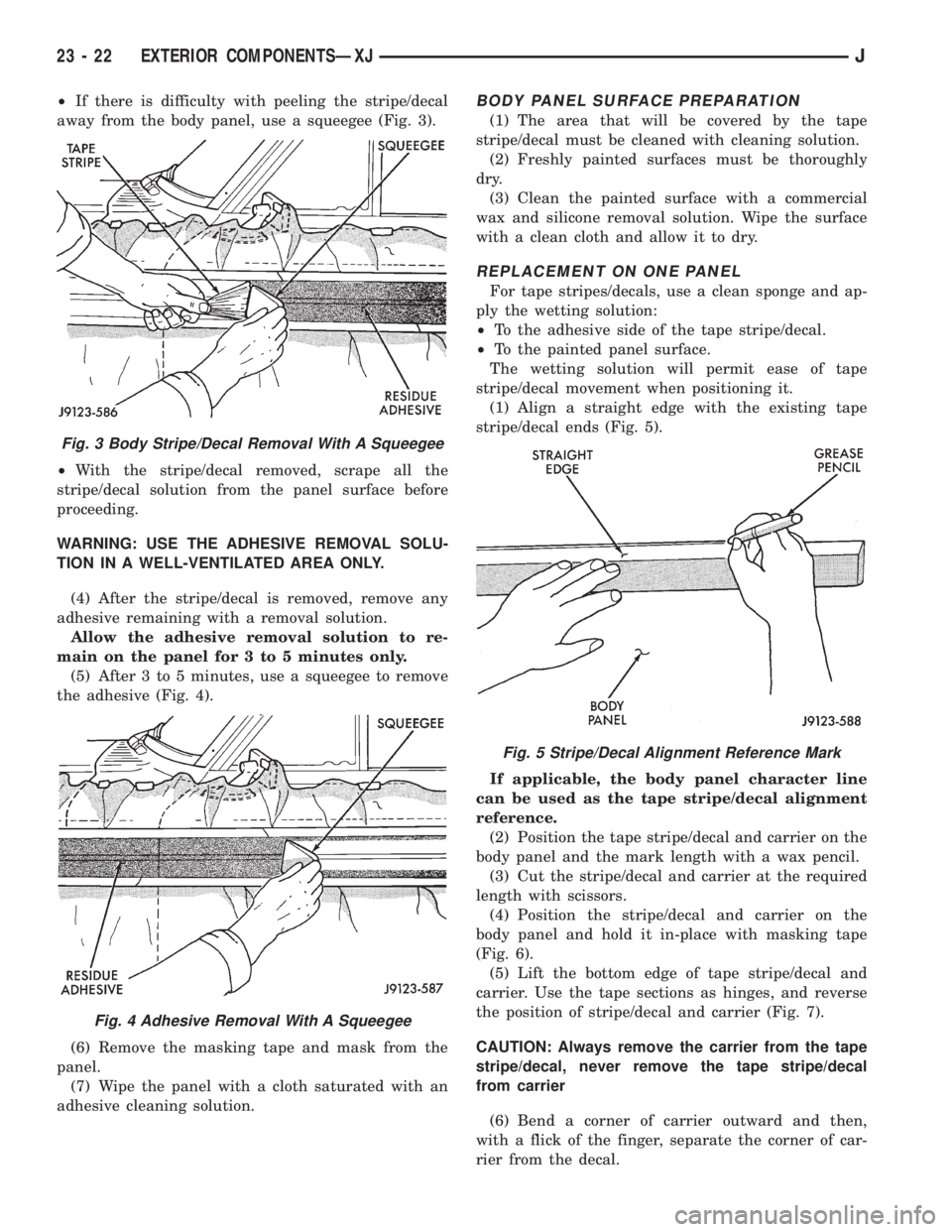
²If there is difficulty with peeling the stripe/decal
away from the body panel, use a squeegee (Fig. 3).
²With the stripe/decal removed, scrape all the
stripe/decal solution from the panel surface before
proceeding.
WARNING: USE THE ADHESIVE REMOVAL SOLU-
TION IN A WELL-VENTILATED AREA ONLY.
(4) After the stripe/decal is removed, remove any
adhesive remaining with a removal solution.
Allow the adhesive removal solution to re-
main on the panel for 3 to 5 minutes only.
(5) After 3 to 5 minutes, use a squeegee to remove
the adhesive (Fig. 4).
(6) Remove the masking tape and mask from the
panel.
(7) Wipe the panel with a cloth saturated with an
adhesive cleaning solution.BODY PANEL SURFACE PREPARATION
(1) The area that will be covered by the tape
stripe/decal must be cleaned with cleaning solution.
(2) Freshly painted surfaces must be thoroughly
dry.
(3) Clean the painted surface with a commercial
wax and silicone removal solution. Wipe the surface
with a clean cloth and allow it to dry.
REPLACEMENT ON ONE PANEL
For tape stripes/decals, use a clean sponge and ap-
ply the wetting solution:
²To the adhesive side of the tape stripe/decal.
²To the painted panel surface.
The wetting solution will permit ease of tape
stripe/decal movement when positioning it.
(1) Align a straight edge with the existing tape
stripe/decal ends (Fig. 5).
If applicable, the body panel character line
can be used as the tape stripe/decal alignment
reference.
(2) Position the tape stripe/decal and carrier on the
body panel and the mark length with a wax pencil.
(3) Cut the stripe/decal and carrier at the required
length with scissors.
(4) Position the stripe/decal and carrier on the
body panel and hold it in-place with masking tape
(Fig. 6).
(5) Lift the bottom edge of tape stripe/decal and
carrier. Use the tape sections as hinges, and reverse
the position of stripe/decal and carrier (Fig. 7).
CAUTION: Always remove the carrier from the tape
stripe/decal, never remove the tape stripe/decal
from carrier
(6) Bend a corner of carrier outward and then,
with a flick of the finger, separate the corner of car-
rier from the decal.
Fig. 3 Body Stripe/Decal Removal With A Squeegee
Fig. 4 Adhesive Removal With A Squeegee
Fig. 5 Stripe/Decal Alignment Reference Mark
23 - 22 EXTERIOR COMPONENTSÐXJJ
Page 1941 of 2158
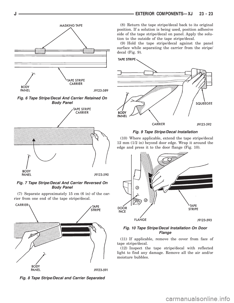
(7) Separate approximately 15 cm (6 in) of the car-
rier from one end of the tape stripe/decal.(8) Return the tape stripe/decal back to its original
position. If a solution is being used, position adhesive
side of the tape stripe/decal on panel. Apply the solu-
tion to the outside of the tape stripe/decal.
(9) Hold the tape stripe/decal against the panel
surface while separating the carrier from the stripe/
decal (Fig. 9).
(10) Where applicable, extend the tape stripe/decal
12 mm (1/2 in) beyond door edge. Wrap it around the
edge and press it to the door flange (Fig. 10).
(11) If applicable, remove the cover from face of
tape stripe/decal.
(12) Inspect the tape stripe/decal with reflected
light to find any damage. Remove all the air and/or
moisture bubbles.
Fig. 6 Tape Stripe/Decal And Carrier Retained On
Body Panel
Fig. 7 Tape Stripe/Decal And Carrier Reversed On
Body Panel
Fig. 8 Tape Stripe/Decal and Carrier Separated
Fig. 9 Tape Stripe/Decal Installation
Fig. 10 Tape Stripe/Decal Installation On Door
Flange
JEXTERIOR COMPONENTSÐXJ 23 - 23
Page 1942 of 2158
COMPLETE REPLACEMENT
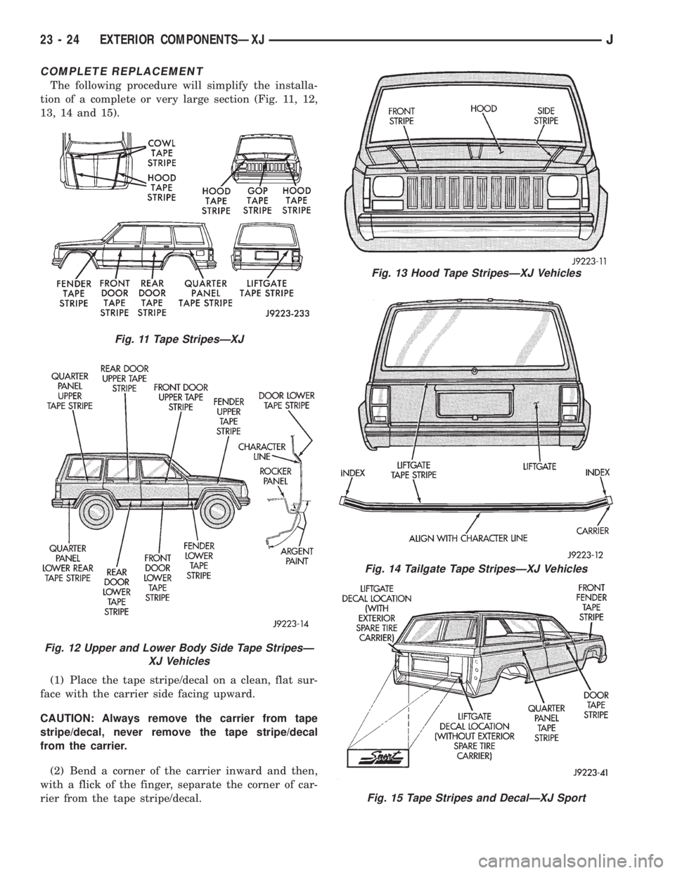
The following procedure will simplify the installa-
tion of a complete or very large section (Fig. 11, 12,
13, 14 and 15).
(1) Place the tape stripe/decal on a clean, flat sur-
face with the carrier side facing upward.
CAUTION: Always remove the carrier from tape
stripe/decal, never remove the tape stripe/decal
from the carrier.
(2) Bend a corner of the carrier inward and then,
with a flick of the finger, separate the corner of car-
rier from the tape stripe/decal.
Fig. 11 Tape StripesÐXJ
Fig. 12 Upper and Lower Body Side Tape StripesÐ
XJ Vehicles
Fig. 13 Hood Tape StripesÐXJ Vehicles
Fig. 14 Tailgate Tape StripesÐXJ Vehicles
Fig. 15 Tape Stripes and DecalÐXJ Sport
23 - 24 EXTERIOR COMPONENTSÐXJJ
Page 1955 of 2158
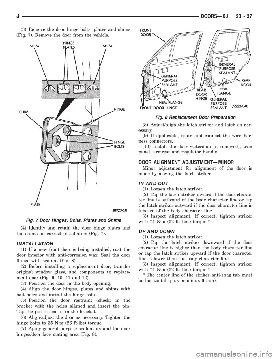
(3) Remove the door hinge bolts, plates and shims
(Fig. 7). Remove the door from the vehicle.
(4) Identify and retain the door hinge plates and
the shims for correct installation (Fig. 7).
INSTALLATION
(1) If a new front door is being installed, coat the
door interior with anti-corrosion wax. Seal the door
flange with sealant (Fig. 8).
(2) Before installing a replacement door, transfer
original window glass, and components to replace-
ment door (Fig. 9, 10, 11 and 12).
(3) Position the door in the body opening.
(4) Align the door hinges, plates and shims with
bolt holes and install the hinge bolts.
(5) Position the door restraint (check) in the
bracket with the holes aligned and insert the pin.
Tap the pin to seat it in the bracket.
(6) Align/adjust the door as necessary. Tighten the
hinge bolts to 35 Nzm (26 ft-lbs) torque.
(7) Apply general purpose sealant around the door
hinges/door face mating area (Fig. 8).(8) Adjust/align the latch striker and latch as nec-
essary.
(9) If applicable, route and connect the wire har-
ness connectors.
(10) Install the door waterdam (if removed), trim
panel, armrest and regulator handle.
DOOR ALIGNMENT ADJUSTMENTÐMINOR
Minor adjustment for alignment of the door is
made by moving the latch striker.
IN AND OUT
(1) Loosen the latch striker.
(2) Tap the latch striker inward if the door charac-
ter line is outboard of the body character line or tap
the latch striker outward if the door character line is
inboard of the body character line.
(3) Inspect alignment. If correct, tighten striker
with 71 Nzm (52 ft. lbs.) torque.*
UP AND DOWN
(1) Loosen the latch striker.
(2) Tap the latch striker downward if the door
character line is higher than the body character line
or tap the latch striker upward if the door character
line is lower than the body character line.
(3) Inspect alignment. If correct, tighten striker
with 71 Nzm (52 ft. lbs.) torque.*
* The center line of the striker anti-snag tab must
be horizontal (plus or minus 6 mm).
Fig. 7 Door Hinges, Bolts, Plates and Shims
Fig. 8 Replacement Door Preparation
JDOORSÐXJ 23 - 37
Page 1990 of 2158
(6) If the pinchweld flanges require repair, remove
the windshield glass and straighten, align, or repair
the flange(s) as necessary.
(7) Position the windshield in the opening and in-
spect the windshield fit again. Mark the windshield
final position on the glass and body with a wax pen-
cil (or use masking tape). The marks (or masking
tape) will be used for installation alignment refer-
ence.
(8) If the replacement windshield does not have
blackout primer:
²Attach a 25-mm (1-in) wide masking tape band
around the interior side of glass 16 mm (5/8 in)
from edge of glass (Fig. 2).
²Do not attach tape along the bottom of the glass
and attach only to the inside of glass.
²Thoroughly mix and apply blackout primer to the
16 mm (5/8 in) surface area around the interior
side of the glass (Fig. 4).
²Allow the primer to dry for at least 10-12 minutes.
(9) Apply a small amount of adhesive to the bot-
tom support spacers and attach the support spacers
to the bottom of the windshield, 170 mm inboard
from the outer windshield edge (Fig. 6).
(10) Cut the urethane applicator nozzle (Fig. 7).
(11) Apply a continuous bead of urethane to the
surface area with blackout primer on the interior
side of glass. The bead should be 9-mm (3/8-in) wide
by 12.7-mm (1/2-in) deep for best results.CAUTION: Be prepared to install the windshield im-
mediately after applying the adhesive, as the adhe-
sive will begin to cure in less than 10 minutes.
(12) Align the windshield with the wax pencil in-
stallation alignment reference marks (or the tape
strips). Position the windshield on pinchweld flanges
and spacers.
(13) Force the windshield inward just enough to
wet-out and set the urethane. Use care to avoid ex-
cessive squeeze-out of adhesive.
(14) Water test the windshield with a water spray
after installation. Do not direct high pressure
streams of water directly at the urethane. If any
leaks are detected, apply urethane as necessary.
(15) If used, remove the masking tape from the in-
ner surface of glass.
(16) Install all components and clean the vehicle. If
necessary, refer to the installation procedures.
(17) Open the vehicle windows to prevent interior
pressure while the urethane adhesive is curing.If
not vented, pressure in the interior of vehicle
will interfere with glass bonding.
(18) Install the rearview mirror on the bracket.
REAR DOOR STATIONARY WINDOW GLASS
REMOVAL
(1) Lower the window glass.
(2) Pry the window beltline molding away from the
clips and remove the molding from the door.
(3) Remove the window weatherstrip seals from
the door.
23 - 72 STATIONARY WINDOW GLASSÐXJJ1995 Jeep Cherokee/Wrangler
Publication No. 81-370-5146
TSB 26-05-95 July, 1995
Page 2020 of 2158
BODY COMPONENTSÐYJ VEHICLES
CONTENTS
page page
DOORS............................... 134
EXTERIOR COMPONENTS................ 104
GENERAL SERVICE INFORMATION......... 102INTERIOR COMPONENTS................ 151
PAINT................................ 158
STATIONARY GLASS.................... 144
GENERAL SERVICE INFORMATION
LABELS/DECALS/PLATESÐYJ
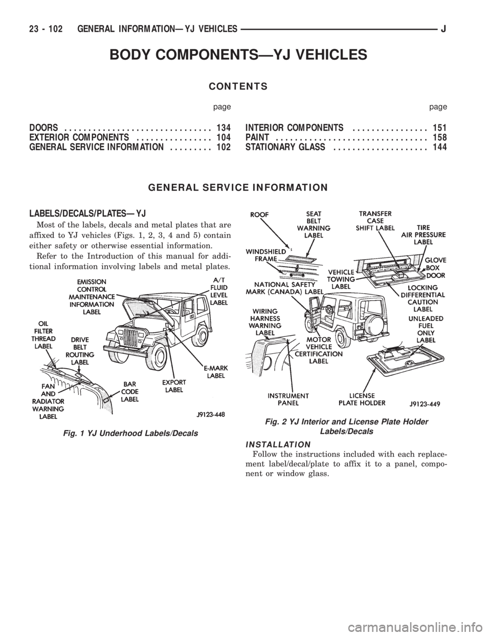
Most of the labels, decals and metal plates that are
affixed to YJ vehicles (Figs. 1, 2, 3, 4 and 5) contain
either safety or otherwise essential information.
Refer to the Introduction of this manual for addi-
tional information involving labels and metal plates.
INSTALLATION
Follow the instructions included with each replace-
ment label/decal/plate to affix it to a panel, compo-
nent or window glass.
Fig. 1 YJ Underhood Labels/Decals
Fig. 2 YJ Interior and License Plate Holder
Labels/Decals
23 - 102 GENERAL INFORMATIONÐYJ VEHICLESJ
Page 2022 of 2158
EXTERIOR COMPONENTS
INDEX
page page
Battery TrayÐYJ......................... 110
Body Side Step MoldingÐYJ................ 115
Body Stripes/DecalsÐYJ................... 116
Cowl Grille and ScreenÐYJ................ 109
Cowl Weatherstrip SealÐYJ................ 109
Exterior Nameplates (Adhesive-Backed)ÐYJ.... 120
External Spare/Wheel Tire CarrierÐYJ........ 133
Fender FlareÐYJ........................ 114
Fender Inner Splash ShieldsÐYJ............. 116
Fender Splash ApronsÐYJ................. 115
FendersÐYJ............................ 110
Fuel Filler Protector/NozzleÐYJ............. 121
Half Metal Door Mirror (External)ÐYJ......... 121
Hard Top Liftgate GlassÐYJ................ 124
Hard Top RepairÐYJ..................... 127
Hard Top Roof VentÐYJ................... 127
Hard TopÐYJ........................... 126Hood AlignmentÐYJ...................... 107
Hood Insulator PanelÐYJ.................. 107
Hood Safety LatchÐYJ.................... 109
HoodÐYJ.............................. 107
Liftgate Glass Weatherstrip Seal ReplacementÐYJ. 125
Radiator Grille AppliqueÐYJ................ 104
Soft Top Service InformationÐYJ............. 127
Soft Top ServiceÐYJ..................... 129
Sport BarÐYJ........................... 132
Tailgate AdjustmentÐYJ................... 121
Tailgate HingeÐYJ....................... 121
Tailgate Latch and Release HandleÐYJ........ 122
Tailgate Latch StrikerÐYJ.................. 123
Tailgate Lock CylinderÐYJ................. 122
Tailgate Weatherstrip SealÐYJ.............. 123
TailgateÐYJ............................ 121
Wheelhouse Splash LinersÐYJ.............. 115
RADIATOR GRILLE APPLIQUEÐYJ
REMOVAL
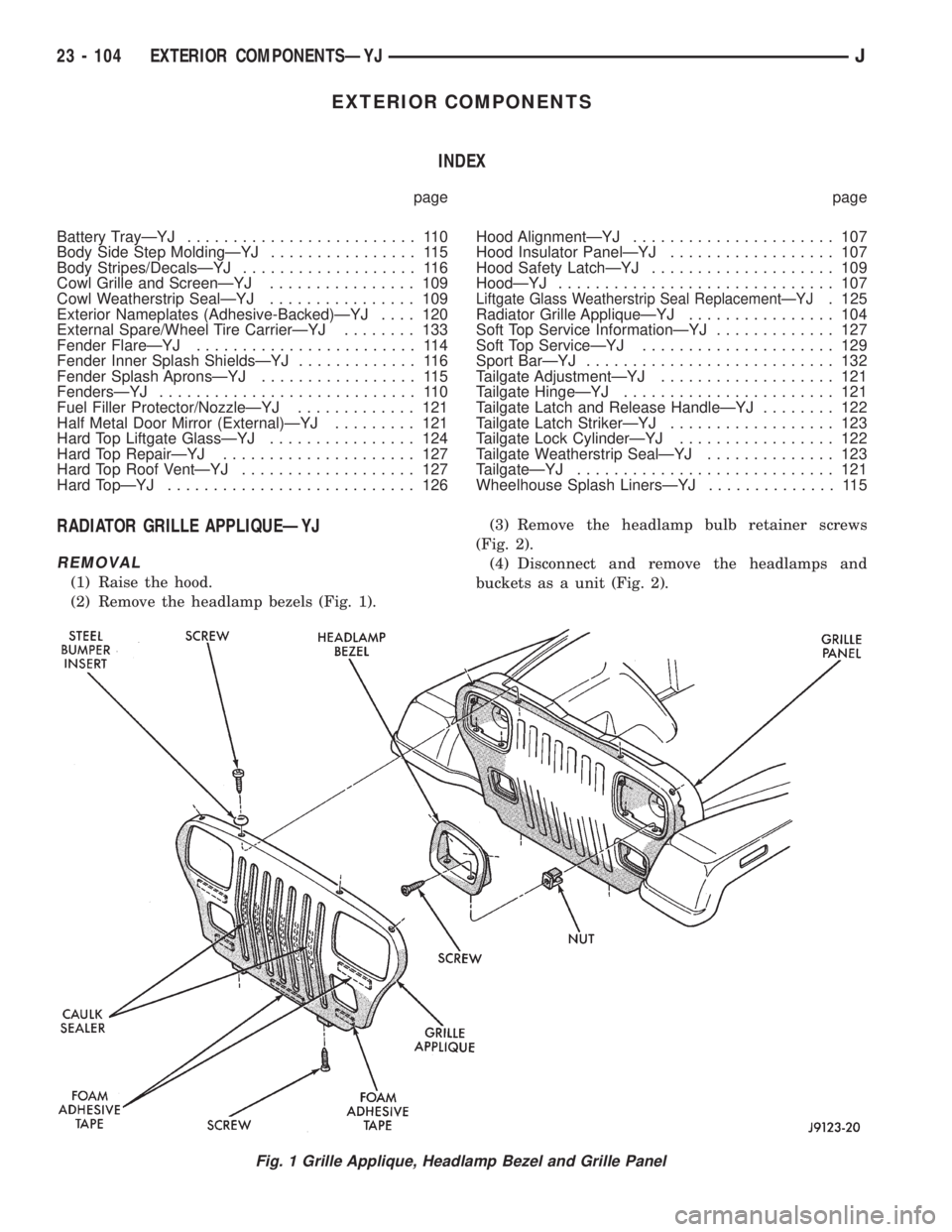
(1) Raise the hood.
(2) Remove the headlamp bezels (Fig. 1).(3) Remove the headlamp bulb retainer screws
(Fig. 2).
(4) Disconnect and remove the headlamps and
buckets as a unit (Fig. 2).
Fig. 1 Grille Applique, Headlamp Bezel and Grille Panel
23 - 104 EXTERIOR COMPONENTSÐYJJ
Page 2031 of 2158
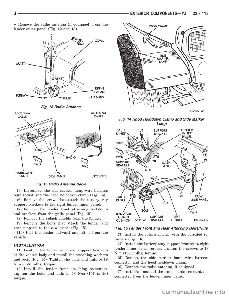
²Remove the radio antenna (if equipped) from the
fender outer panel (Fig. 12 and 13).
(5) Disconnect the side marker lamp wire harness
bulb socket and the hood holddown clamp (Fig. 14).
(6) Remove the screws that attach the battery tray
support brackets to the right fender inner panel.
(7) Remove the fender front attaching bolts/nuts
and brackets from the grille panel (Fig. 15).
(8) Remove the splash shields from the fender.
(9) Remove the bolts that attach the fender and
rear supports to the cowl panel (Fig. 15).
(10) Pull the fender outward and lift it from the
vehicle.
INSTALLATION
(1) Position the fender and rear support brackets
at the vehicle body and install the attaching washers
and bolts (Fig. 15). Tighten the bolts and nuts to 18
Nzm (156 in-lbs) torque.
(2) Install the fender front attaching bolts/nuts.
Tighten the bolts and nuts to 18 Nzm (156 in-lbs)
torque.(3) Install the splash shields with the serrated re-
tainers (Fig. 16).
(4) Install the battery tray support bracket-to-right
fender inner panel screws. Tighten the screws to 18
Nzm (156 in-lbs) torque.
(5) Connect the side marker lamp wire harness
connector and the hood holddown clamp.
(6) Connect the radio antenna, if equipped.
(7) Install/connect all the components removed/dis-
connected from the fender inner panel.
Fig. 12 Radio Antenna
Fig. 13 Radio Antenna Cable
Fig. 14 Hood Holddown Clamp and Side Marker
Lamp
Fig. 15 Fender Front and Rear Attaching Bolts/Nuts
JEXTERIOR COMPONENTSÐYJ 23 - 113