1995 JEEP YJ instrument cluster
[x] Cancel search: instrument clusterPage 889 of 2158
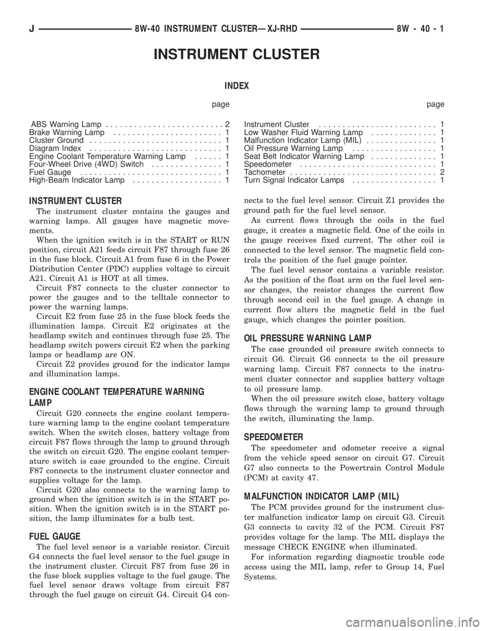
INSTRUMENTCLUSTER
Page 890 of 2158
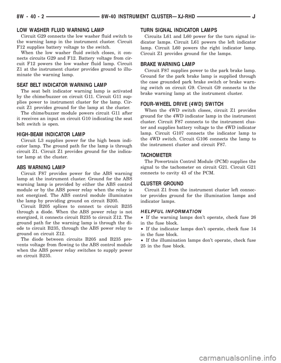
LOW WASHER FLUID WARNING LAMP
Circuit G29 connects the low washer fluid switch to
the warning lamp in the instrument cluster. Circuit
F12 supplies battery voltage to the switch.
When the low washer fluid switch closes, it con-
nects circuits G29 and F12. Battery voltage from cir-
cuit F12 powers the low washer fluid lamp. Circuit
Z1 at the instrument cluster provides ground to illu-
minate the warning lamp.
SEAT BELT INDICATOR WARNING LAMP
The seat belt indicator warning lamp is activated
by the chime/buzzer on circuit G11. Circuit G11 sup-
plies power to instrument cluster for the lamp. Cir-
cuit Z1 provides ground for the lamp at the cluster.
The chime/buzzer module powers circuit G11 after
it receives an input on circuit G10 indicating the seat
belt switch is open.
HIGH-BEAM INDICATOR LAMP
Circuit L3 supplies power for the high beam indi-
cator lamp. The ground path for the lamp is through
circuit Z1. Circuit Z1 provides ground for the indica-
tor lamp at the cluster.
ABS WARNING LAMP
Circuit F87 provides power for the ABS warning
lamp at the instrument cluster. Ground for the ABS
warning lamp is provided by either the ABS control
module or by the ABS power relay when the relay is
not energized. The ABS control module illuminates
the lamp by providing ground on circuit B205.
Circuit B205 splices to connect to circuit B235
through a diode. When the ABS power relay is not
energized, it connects circuit B235 to circuit Z12. The
ground path for the warning lamp is through the di-
ode to circuit B235, through the ABS power relay to
ground on circuit Z12.
The diode between circuits B205 and B235 pre-
vents voltage from flowing to the ABS control module
when the ABS power relay switches to supply power
on circuit B235.
TURN SIGNAL INDICATOR LAMPS
Circuits L61 and L60 power for the turn signal in-
dicator lamps. Circuit L61 powers the left indicator
lamp. Circuit L60 powers the right indicator lamp.
Circuit Z1 provides ground for the lamps.
BRAKE WARNING LAMP
Circuit F87 supplies power to the park brake lamp.
Ground for the park brake lamp is supplied through
the case grounded park brake switch or brake warn-
ing switch on circuit G9. Circuit G9 connects to the
brake warning lamp at the instrument cluster.
FOUR-WHEEL DRIVE (4WD) SWITCH
When the 4WD switch closes, circuit Z1 provides
ground for the 4WD indicator lamp in the instrument
cluster. Circuit F87 connects to the instrument clus-
ter and supplies battery voltage to the 4WD indicator
lamp. Circuit G107 connects the indicator lamp to
the 4WD switch. Circuit G106 connects the lamp to
the instrument cluster and circuit F87.
TACHOMETER
The Powertrain Control Module (PCM) supplies the
signal to the tachometer on circuit G21. Circuit G21
connects to cavity 43 of the PCM.
CLUSTER GROUND
Circuit Z1 from the instrument cluster left connec-
tor provides ground for the illumination lamps and
indicator lamps.
HELPFUL INFORMATION
²If the warning lamps don't operate, check fuse 26
in the fuse block.
²If the indicator lamps don't operate, check fuse 14
in the fuse block.
²If the illumination lamps don't operate, check fuse
25 in the fuse block.
8W - 40 - 2 8W-40 INSTRUMENT CLUSTERÐXJ-RHDJ
Page 891 of 2158
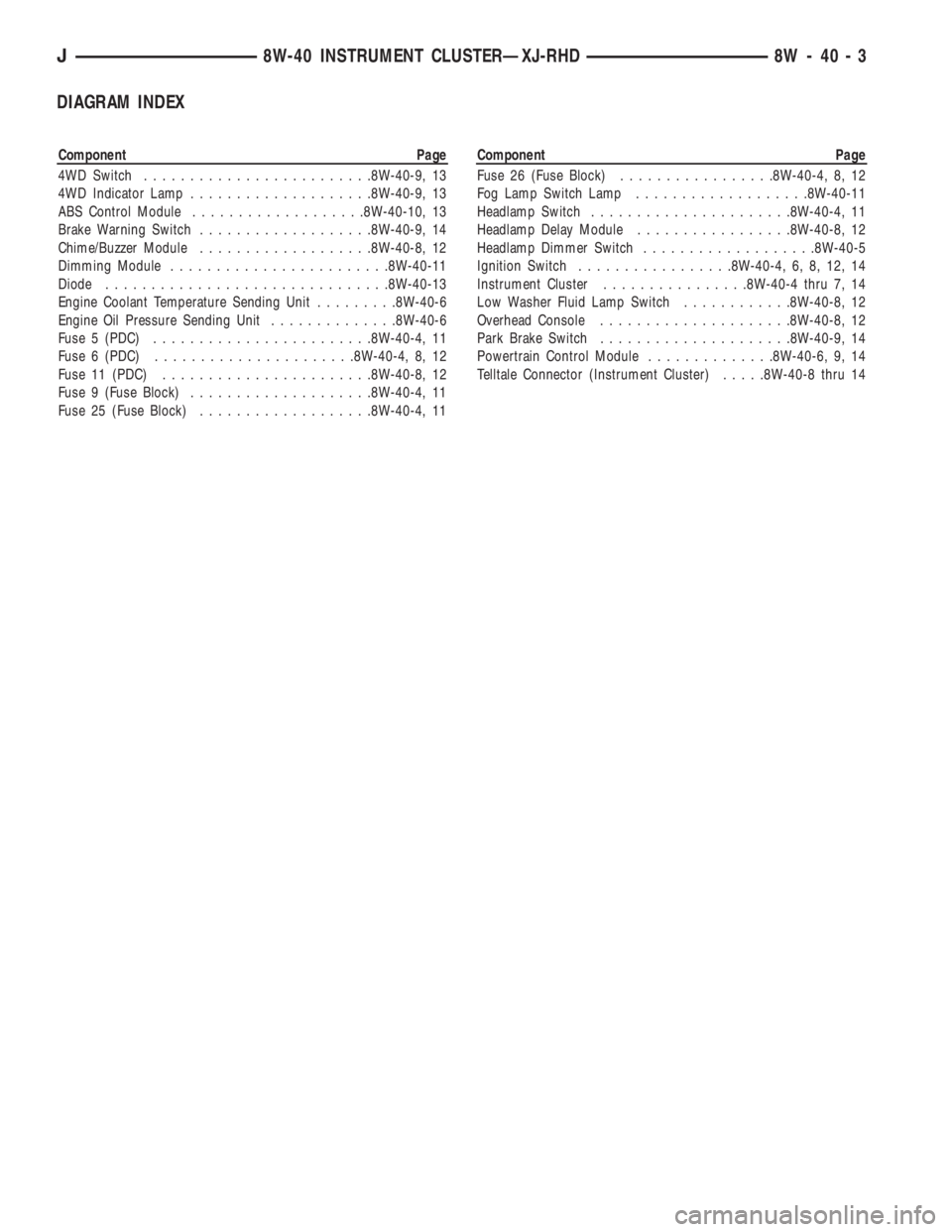
DIAGRAM INDEX
Component Page
4WD Switch.........................8W-40-9, 13
4WD Indicator Lamp....................8W-40-9, 13
ABS Control Module...................8W-40-10, 13
Brake Warning Switch...................8W-40-9, 14
Chime/Buzzer Module...................8W-40-8, 12
Dimming Module........................8W-40-11
Diode...............................8W-40-13
Engine Coolant Temperature Sending Unit.........8W-40-6
Engine Oil Pressure Sending Unit..............8W-40-6
Fuse 5 (PDC)........................8W-40-4, 11
Fuse 6 (PDC)......................8W-40-4, 8, 12
Fuse 11 (PDC).......................8W-40-8, 12
Fuse 9 (Fuse Block)....................8W-40-4, 11
Fuse 25 (Fuse Block)...................8W-40-4, 11Component Page
Fuse 26 (Fuse Block).................8W-40-4, 8, 12
Fog Lamp Switch Lamp...................8W-40-11
Headlamp Switch......................8W-40-4, 11
Headlamp Delay Module.................8W-40-8, 12
Headlamp Dimmer Switch...................8W-40-5
Ignition Switch.................8W-40-4, 6, 8, 12, 14
Instrument Cluster................8W-40-4 thru 7, 14
Low Washer Fluid Lamp Switch............8W-40-8, 12
Overhead Console.....................8W-40-8, 12
Park Brake Switch.....................8W-40-9, 14
Powertrain Control Module..............8W-40-6, 9, 14
Telltale Connector (Instrument Cluster).....8W-40-8 thru 14
J8W-40 INSTRUMENT CLUSTERÐXJ-RHD 8W - 40 - 3
Page 913 of 2158

INTERIOR LIGHTING
INDEX
page page
Cargo Lamp and Dome Lamp................. 1
Chime/Buzzer Module....................... 2
Diagram Index............................ 2
General Information........................ 1
Glove Box Lamp........................... 1Ignition Switch Lamp........................ 1
Instrument Panel Illumination Lamps............ 1
Reading Lamps........................... 1
Underhood Lamp.......................... 1
Visor Vanity Mirror Lamps.................... 1
GENERAL INFORMATION
Circuit M1 supplies power to the glove box lamp,
dome lamp, reading lamps, cargo lamp and vanity
lamps. Circuit M1 is protected by fuse 16 in the
Power Distribution Center (PDC).
Circuit E2 supplies power for the instrument panel
illumination lamps.
INSTRUMENT PANEL ILLUMINATION LAMPS
Circuit E2 from the headlamp switch splices to
supply power to the following illumination lamps:
²Ash receiver lamp
²Cigar lighter lamp
²Transmission range indicator lamp
²Transfer case range indicator lamp
²A/C-Heater switch lamp
²Heated rear window switch lamp
²Rear wiper switch lamp
²Fog lamp switch lamp
Fuse 25 in the fuse block protects circuit E2. Cir-
cuit Z1 provides ground for all of the illumination
lamps except for the cigar lighter lamp. The cigar
lighter lamp is case grounded.
HELPFUL INFORMATION
Circuit E2 also supplies power to the radio, LCD
relay and the illumination lamps in the instrument
cluster.
IGNITION SWITCH LAMP
Circuit M50 supplies voltage to the ignition switch
lamp. Circuit Z1 provides ground for the lamp.
GLOVE BOX LAMP
Circuit M1 from fuse 16 in the Power Distribution
Center (PDC) powers the glove box lamp. A case
grounded switch, in series after the lamp, closes
when the glove box door is opened. The switch com-
pletes a path to ground on circuit Z1.
CARGO LAMP AND DOME LAMP
Circuit M1 from fuse 16 in the Power Distribution
Center (PDC) supplies power to the cargo lamp anddome lamp. The M1 circuit is HOT at all times. The
ground path for the lamp is provided in three differ-
ent ways.
One way is through the door jamb switches. Circuit
M2 connects to the door jamb switches to the dome
lamp and cargo lamp. The switches are connected to
ground circuit Z1. When a door is opened, the
plunger in the switch closes, completing a path to
ground.
The second way is through the liftgate switch. Cir-
cuit G71 connects to circuit M2 at the cargo lamp
connector. Circuit G71 connects to the liftgate switch.
The liftgate switch connects to ground circuit Z1.
When the lift gate opens, the plunger in the switch
closes, completing a path to ground.
The third ground path is through the headlamp
switch. Circuit M2 is spliced in with the headlamp
switch. When the operator turns the headlamp
switch to the dome lamp ON position, a ground path
is provided through the switch.
READING LAMPS
Circuit M1 from fuse 16 in the Power Distribution
Center (PDC) supplies power to the reading lamps.
Circuit M1 is HOT at all times. When the operator
depresses the reading lamp, the reading lamp switch
closes and supplies ground on circuit Z1.
VISOR VANITY MIRROR LAMPS
Circuit M1 from fuse 16 in the Power Distribution
Center (PDC) supplies power to the vanity lamps.
Circuit M1 is HOT at all times. When the vanity
lamps switch closes, voltage flows to vanity mirror
lamps. The vanity mirror is case grounded.
UNDERHOOD LAMP
Circuit A7 from fuse 16 in the Power Distribution
Center (PDC) supplies battery voltage for the under-
hood lamp. A mercury switch, in series after the
lamp, connects the lamp to ground on circuit Z1.
When the hood is raised, mercury inside the switch
moves to a position where it connects circuit M1 to
ground circuit Z1, illuminating the lamp.
J8W-44 INTERIOR LIGHTINGÐXJ-RHD 8W - 44 - 1
Page 914 of 2158

CHIME/BUZZER MODULE
The buzzer or optional chime module sounds an au-
dible warning tone. The tone sounds for seat belt
warning and when the ignition key is in the ignition
switch while the drivers door is open. The tone also
sounds when the ignition key is in the ON position
while the drivers side seat belt is not buckled. Lastly,
the tone sounds when the headlamps are ON when
the ignition is OFF. Refer to Group 8U for system op-
eration.
When the ignition switch is in the RUN or START
position, fuse F87 from fuse 26 in the fuse block sup-
plies power to the chime/buzzer module. Circuit A21
from the ignition switch supplies power to fuse 26.
Circuit L7 from fuse 9 in the fuse block also sup-
plies power to the chime/buzzer module. Circuit A3
from fuse 5 in the Power Distribution Center (PDC)
powers fuse 9.
When the parking lamps or headlamps are ON, the
headlamp switch connects circuit G26 with the driv-
ers side door jamb switch. Circuit G26 also connects
to the key-in switch. Circuit M11 connects the key-in
switch to the chime module and the headlamp
switch.
If the headlamps are ON, and the drivers door
opens, ground for the chime/buzzer is on circuit C26
from the headlamp switch through the door jamb
switch to circuit Z1.
If the headlamps are OFF with the key in the ig-
nition while the drivers side door is open, ground for
the chime/buzzer is supplied through the key-in
switch. The ground path is over circuit M11, through
the closed key-in switch to circuit C26. From circuit
C26, the ground path continues through the drivers
door jamb switch to circuit Z1.
Circuit G11 from the buzzer powers the seat belt
warning lamp in the instrument cluster. Circuit Z1
at the instrument cluster provides ground for the
lamp.Circuit G10 from the buzzer connects to the seat
belt switch. When the seat belt switch closes a path
to ground is completed on circuit Z1 and the tone
sounds momentarily.
Circuit Z1 also grounds the chime buzzer module.
HELPFUL INFORMATION
Circuit F87 also powers the instrument cluster and
the headlamp delay module.
DIAGRAM INDEX
Component Page
Cargo Lamp............................8W-44-6
Chime/Buzzer Module......................8W-44-3
Courtesy Lamps.........................8W-44-5
Dome Lamp............................8W-44-6
Door Jamb Switches......................8W-44-7
Fuse 3 (PDC)...........................8W-44-6
Fuse 5 (PDC).........................8W-44-5, 8
Fuse 6 (PDC)...........................8W-44-6
Fuse 9 (Fuse Block).....................8W-44-3, 8
Fuse 16 (PDC)........................8W-44-4, 6
Fuse 25 (Fuse Block)......................8W-44-8
Fuse 26 (Fuse Block)......................8W-44-3
Glove Box Lamp and Switch.................8W-44-5
Headlamp Switch....................8W-44-3, thru 8
Headlamp Delay Module....................8W-44-3
Ignition Switch..........................8W-44-3
Instrument Cluster......................8W-44-3, 9
Instrument Panel Illumination Lamps..........8W-44-8, 9
Key-In Switch...........................8W-44-4
Liftgate Switch..........................8W-44-6
Reading Lamps..........................8W-44-6
Seat Belt Switch.........................8W-44-3
Telltale Connector (Instrument Cluster)...........8W-44-3
Time Delay Relay........................8W-44-4
Underhood Lamp.........................8W-44-4
8W - 44 - 2 8W-44 INTERIOR LIGHTINGÐXJ-RHDJ
Page 935 of 2158

OVERHEAD CONSOLE
OVERHEAD CONSOLE
When the ignition switch is in the START or RUN
position, it connects circuit A1 from fuse 6 in the
Power Distribution Center (PDC) to circuit A21. Cir-
cuit A21 supplies power to circuit F87 through fuse
26 in the fuse block. Circuit F87 supplies power to
the overhead console.
When the headlamps or parking lamps are ON, cir-
cuits L90 and E2 provide voltage to the overhead
console for illumination. Voltage on circuit L90 in-
forms the overhead console that the headlamps or
parking lamps are ON. Circuit E2 from the head
lamp switch powers the illumination lamps in the
overhead console. Circuit E2 also powers fuse 25 in
the fuse block.
Circuits Z1 and Z2 provides ground for the over-
head console. From circuit M2, the overhead console
senses when one of the door jamb switches opens.
AMBIENT TEMPERATURE SENSOR
The ambient temperature sensor is a variable re-
sistor. Circuit G31 supplies voltage from the over-
head console to the sensor. Circuit G32 is the signal
return from the sensor to the overhead console.
LAMPS
Circuit M1 supplies voltage for the case grounded
reading lamps in the overhead console. Fuse 16 in
the Power Distribution Center (PDC) supplies volt-
age to circuit M1 through circuit A7. Circuit A7 from
fuse 3 in the PDC supplies voltage to fuse 16 in the
PDC.
DIAGRAM INDEX
Component Page
Ambient Temperature Sensor.................8W-49-4
Chime/Buzzer Module......................8W-49-2
Fuse 3 (PDC)...........................8W-49-2
Fuse 5 (PDC)...........................8W-49-3
Fuse 6 (PDC)...........................8W-49-2
Fuse 9 (Fuse Block).......................8W-49-3
Fuse 16 (PDC)..........................8W-49-2
Fuse 26 (Fuse Block)......................8W-49-2
Headlamp Delay Module....................8W-49-2
Headlamp Switch.........................8W-49-3
Ignition Switch..........................8W-49-2
Instrument Cluster........................8W-49-4
Overhead Console....................8W-49-2, 3, 4
Telltale Connector (Instrument Cluster)...........8W-49-2
J8W-49 OVERHEAD CONSOLEÐXJ-RHD 8W - 49 - 1
Page 941 of 2158
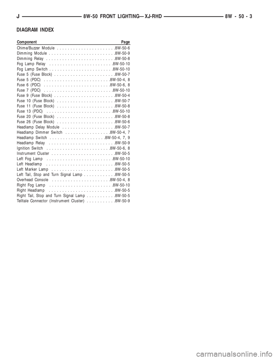
DIAGRAM INDEX
Component Page
Chime/Buzzer Module......................8W-50-6
Dimming Module.........................8W-50-9
Dimming Relay..........................8W-50-8
Fog Lamp Relay........................8W-50-10
Fog Lamp Switch........................8W-50-10
Fuse 5 (Fuse Block).......................8W-50-7
Fuse 5 (PDC).........................8W-50-4, 8
Fuse 6 (PDC).........................8W-50-6, 8
Fuse 7 (PDC)..........................8W-50-10
Fuse 9 (Fuse Block).......................8W-50-4
Fuse 10 (Fuse Block)......................8W-50-7
Fuse 11 (Fuse Block)......................8W-50-8
Fuse 13 (PDC).........................8W-50-10
Fuse 20 (Fuse Block)......................8W-50-8
Fuse 26 (Fuse Block)......................8W-50-6
Headlamp Delay Module....................8W-50-7
Headlamp Dimmer Switch.................8W-50-4, 7
Headlamp Switch.....................8W-50-4, 7, 9
Headlamp Relay.........................8W-50-9
Ignition Switch........................8W-50-6, 8
Instrument Cluster........................8W-50-5
Left Fog Lamp.........................8W-50-10
Left Headlamp..........................8W-50-5
Left Marker Lamp........................8W-50-5
Left Tail, Stop and Turn Signal Lamp............8W-50-5
Overhead Console......................8W-50-4, 8
Right Fog Lamp........................8W-50-10
Right Headlamp.........................8W-50-5
Right Tail, Stop and Turn Signal Lamp...........8W-50-5
Telltale Connector (Instrument Cluster)...........8W-50-9
J8W-50 FRONT LIGHTINGÐXJ-RHD 8W - 50 - 3
Page 955 of 2158
TURN SIGNALS
TURN SIGNAL RELAY
In the RUN position, the ignition switch connects
circuit A1 from fuse 6 in the Power Distribution Cen-
ter (PDC) to circuit A21. Circuit A21 connects to the
turn signal relay.
Circuit L9 from fuse 4 in the PDC supplies battery
voltage to the relay. Circuit Z1 provides ground for
the relay.
Circuit L5 from the relay connects to the multi-
function switch to supply power to the turn signals.
The multi-function switch supplies voltage to the
turn signals and side marker lamps on circuits L60
and L61.
Circuit L12 from the relay connects to the multi-
function switch and the hazard flasher relay.
TURN SIGNALS
When the operator selects the right turn signal, the
multi-function switch connects power from circuit L5
to circuit L60. Circuit L60 feeds the right front and
right rear turn signal lamp. Circuit L60 also splices
to power the right turn signal indicator lamp on the
instrument cluster.
When the operator selects the right turn signal, the
multi-function switch connects power from circuit L5
to circuit L61. Circuit L61 feeds the left front and
left rear turn signal lamp. Circuit L61 also splices to
power the left turn signal indicator lamp on the in-
strument cluster.
Circuit Z1 provides ground for the turn signal
lamps.
HELPFUL INFORMATION
²The turn signal lamps are the same lamps used
for the hazard flasher.
²Check fuse 6 in the PDC.
HAZARD FLASHERS
When the operator selects the hazard flashers, the
multi-function switch connects circuit L12 from the
hazard flasher relay to circuits L60 and L61.
Circuit L60 feeds the right front and right rear
turn signal lamp. Circuit L60 also splices to power
the right turn signal indicator lamp on the instru-
ment cluster.
Circuit L61 feeds the left front and left rear turn
signal lamp. Circuit L61 also splices to power the left
turn signal indicator lamp on the instrument cluster.
Circuit Z1 provides ground for the hazard flasher
lamps.
HELPFUL INFORMATION
²The hazard flasher lamps are the same lamps
used for the turn signals.
DIAGRAM INDEX
Component Page
ABS Control Module......................8W-52-3
Flasher Relay...........................8W-52-2
Fuse 4 (PDC)...........................8W-52-2
Fuse 6 (PDC)...........................8W-52-2
Ignition Switch..........................8W-52-2
Instrument Cluster........................8W-52-2
Powertrain Control Module..................8W-52-3
Stop Lamp Switch........................8W-52-3
Transmission Control Module.................8W-52-3
Telltale Connector (Instrument Cluster)...........8W-52-4
Turn Signal Relay........................8W-52-4
Turn Signal Switch.......................8W-52-2
J8W-52 TURN SIGNALSÐXJ-RHD 8W - 52 - 1