1995 JEEP XJ ratio
[x] Cancel search: ratioPage 1 of 2158

CHRYSLER
CORPORATION
SERVICE MANUAL
1995 JEEP
To order the special service tools used and
illustrated, please refer to the instructions on
inside back cover.
NO PART OF THIS PUBLICATION MAY BE
REPRODUCED, STORED IN A RETRIEVAL
SYSTEM, OR TRANSMITTED, IN ANY FORM
OR BY ANY MEANS, ELECTRONIC, ME-
CHANICAL, PHOTOCOPYING, RECORDING,
OR OTHERWISE, WITHOUT THE PRIOR
WRITTEN PERMISSION OF CHRYSLER
CORPORATION.
Chrysler Corporation reserves the right to make changes in design or to
make additions to or improvements in its products without imposing any ob-
ligations upon itself to install them on its products previously manufactured.
Litho in U.S.A. Copyright 1994 Chrysler Corporation 20M0694
NEXT PAGE©
Page 2 of 2158
FOREWORD
The information contained in this service manual has been prepared for the professional automotive tech-
nician involved in daily repair operations. This manual does not cover theory of operation, which is addressed
in service training material. Information describing the operation and use of standard and optional equipment
is included in the Owner 's Manual provided with the vehicle.
Information in this manual is divided into groups. These groups contain general information, diagnosis,
testing, adjustments, removal, installation, disassembly, and assembly procedures for the components. To as-
sist in locating a group title page, use the Group Tab Locator on the following page. The solid bar after the
group title is aligned to a solid tab on the first page of each group. The first page of the group has a contents
section that lists major topics within the group. If you are not sure which Group contains the information you
need, look up the Component/System in the alphabetical index located in the rear of this manual.
A Service Manual Comment form is included at the rear of this manual. Use the form to provide Chrysler
Corporation with your comments and suggestions.
Tightening torques are provided as a specific value throughout this manual. This value represents the
midpoint of the acceptable engineering torque range for a given fastener application. These torque values are
intended for use in service assembly and installation procedures using the correct OEM fasteners. When re-
placing fasteners, always use the same type (part number) fastener as removed.
Chrysler Corporation reserves the right to change testing procedures, specifications, diagnosis, repair
methods, or vehicle wiring at any time without prior notice or incurring obligation.
NOTE: The acronyms, terminology and nomenclature used to identify emissions related components in
this manual may have changed from prior publications. These new terms are in compliance with S.A.E.
recommended practice J1930.
NEXT PAGE©
Page 4 of 2158
INTRODUCTION
CONTENTS
page page
DESIGNATIONS, LABELS/PLATES, CODES AND
DIMENSIONS.......................... 1MEASUREMENT AND TORQUE
SPECIFICATIONS...................... 11
DESIGNATIONS, LABELS/PLATES, CODES AND DIMENSIONS
INDEX
page page
Engine and Transmission/Transfer Case
Identification............................ 5
International Vehicle Control and Display Symbols . . 5
Major Component Identification................ 5
Trailer Towing Specifications.................. 5
Vehicle Code Plate......................... 4Vehicle Designations........................ 1
Vehicle Dimension Data..................... 5
Vehicle Identification Number (VIN) Plate......... 4
Vehicle Load Data......................... 5
Vehicle Safety Certification Label............... 4
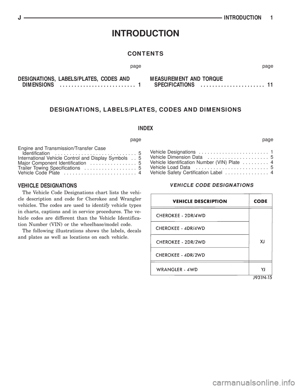
VEHICLE DESIGNATIONS
The Vehicle Code Designations chart lists the vehi-
cle description and code for Cherokee and Wrangler
vehicles. The codes are used to identify vehicle types
in charts, captions and in service procedures. The ve-
hicle codes are different than the Vehicle Identifica-
tion Number (VIN) or the wheelbase/model code.
The following illustrations shows the labels, decals
and plates as well as locations on each vehicle.
VEHICLE CODE DESIGNATIONS
JINTRODUCTION 1
Page 20 of 2158

LUBRICATION AND MAINTENANCE
CONTENTS
page page
CHASSIS AND BODY COMPONENTS........ 28
DRIVETRAIN........................... 22
ENGINE MAINTENANCE................... 15GENERAL INFORMATION.................. 1
JUMP STARTING, TOWING AND HOISTING.... 9
MAINTENANCE SCHEDULES................ 4
GENERAL INFORMATION
INDEX
page page
Classification of Lubricants................... 2
Components Requiring No Lubrication........... 2
Fluid Capacities........................... 3
Fuel Requirements......................... 1International Symbols....................... 1
Introduction.............................. 1
Lubrication and Replacement Parts
Recommendation......................... 2
INTRODUCTION
Lubrication and maintenance is divided into re-
quired and recommended service tasks. The required
service tasks must be completed to verify the emis-
sion controls function correctly. The recommended
service tasks should be completed to maintain safety
and durability.
This information will assist the service personnel
in providing maximum protection for each owner's
vehicle.
Conditions can vary with individual driving habits.
It is necessary to schedule maintenance as a time in-
terval as well as a distance interval.
It is the owner's responsibility to determine the ap-
plicable driving condition. Also to have the vehicle
serviced according to the maintenance schedule, and
to pay for the necessary parts and labor.
Additional maintenance and lubrication informa-
tion is listed in the Owner's Manual.
INTERNATIONAL SYMBOLS
Chrysler Corporation uses international symbols to
identify engine compartment lubricant and fluid in-
spection and fill locations (Fig. 1).
FUEL REQUIREMENTS
All gasoline engines require the use of unleaded
gasoline to reduce the potentially harmful effects of
lead to the environment. Also unleaded fuel is neces-
sary to prevent damage to the catalytic converter/O2sensor. The fuel must have a minimum octane rating
of 87 based on the (R + M)/2 calculation method.
CAUTION: UNLEADED FUEL ONLY must be used in
vehicles equipped with a catalyst emission control
system. All vehicles have reminders printed on the
instrument panel below the fuel gauge and on the
fuel filler door. The vehicles also have fuel filler
tubes that are specially designed to accept only the
small-diameter dispensing nozzles. It is illegal to
bypass the design of an unleaded fuel filler tube
and contaminate the fuel system.
Fig. 1 International Symbols
JLUBRICATION AND MAINTENANCE 0 - 1
Page 21 of 2158
CLASSIFICATION OF LUBRICANTS
Lubricating fluids and chassis lubricants are clas-
sified according to standards recommended by the:
²Society of Automotive Engineers (SAE)
²American Petroleum Institute (API)
²National Lubricating Grease Institute (NLGI)
ENGINE OIL
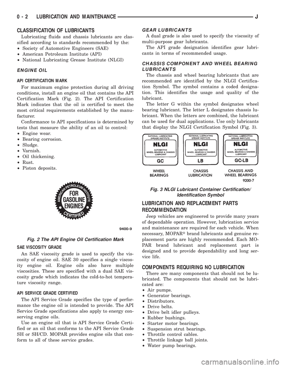
API CERTIFICATION MARK
For maximum engine protection during all driving
conditions, install an engine oil that contains the API
Certification Mark (Fig. 2). The API Certification
Mark indicates that the oil is certified to meet the
most critical requirements established by the manu-
facturer.
Conformance to API specifications is determined by
tests that measure the ability of an oil to control:
²Engine wear.
²Bearing corrosion.
²Sludge.
²Varnish.
²Oil thickening.
²Rust.
²Piston deposits.
SAE VISCOSITY GRADE
An SAE viscosity grade is used to specify the vis-
cosity of engine oil. SAE 30 specifies a single viscos-
ity engine oil. Engine oils also have multiple
viscosities. These are specified with a dual SAE vis-
cosity grade which indicates the cold-to-hot tempera-
ture viscosity range.
API SERVICE GRADE CERTIFIED
The API Service Grade specifies the type of perfor-
mance the engine oil is intended to provide. The API
Service Grade specifications also apply to energy con-
serving engine oils.
Use an engine oil that is API Service Grade Certi-
fied or an oil that conforms to the API Service Grade
SH or SH/CD. MOPAR provides engine oils that con-
form to all of these service grades.
GEAR LUBRICANTS
A dual grade is also used to specify the viscosity of
multi-purpose gear lubricants.
The API grade designation identifies gear lubri-
cants in terms of recommended usage.
CHASSIS COMPONENT AND WHEEL BEARING
LUBRICANTS
The chassis and wheel bearing lubricants that are
recommended are identified by the NLGI Certifica-
tion Symbol. The symbol contains a coded designa-
tion. This identifies the usage and quality of the
lubricant.
The letter G within the symbol designates wheel
bearing lubricant. The letter L designates chassis lu-
bricant. When the letters are combined, the lubricant
can be used for dual applications. Use only lubricants
that display the NLGI Certification Symbol (Fig. 3).
LUBRICATION AND REPLACEMENT PARTS
RECOMMENDATION
Jeep vehicles are engineered to provide many years
of dependable operation. However, lubrication service
and maintenance are required for each vehicle. When
necessary, MOPARtbrand lubricants and genuine re-
placement parts are highly recommended. Each MO-
PAR brand lubricant and replacement part is
designed and to provide dependability and long ser-
vice life.
COMPONENTS REQUIRING NO LUBRICATION
There are many components that should not be lu-
bricated. The components that should not be lubri-
cated are:
²Air pumps.
²Generator bearings.
²Distributors.
²Drive belts.
²Drive belt idler pulleys.
²Rubber bushings.
²Starter motor bearings.
²Suspension strut bearings.
²Throttle control cables.
²Throttle linkage ball joints.
²Water pump bearings.
Fig. 2 The API Engine Oil Certification Mark
Fig. 3 NLGI Lubricant Container Certification/
Identification Symbol
0 - 2 LUBRICATION AND MAINTENANCEJ
Page 23 of 2158

MAINTENANCE SCHEDULES
INTRODUCTION
There are two maintenance schedules that show
proper service intervals for Jeep Cherokee and Jeep
Wrangler vehicles. Use the schedule that best de-
scribes the conditions the vehicle is operated under.
When mileage and time is listed, follow the interval
that occurs first.
ScheduleÐAlists all the scheduled maintenance
to be performed under normal operating conditions.
ScheduleÐBis a schedule for vehicles that are
usually operated under one or more of the following
conditions.
²Frequent short trip driving less than 5 miles (8
km).
²Frequent driving in dusty conditions.
²Trailer towing or heavy load hauling.
²Frequent long periods of engine idling.
²Sustained high speed operation.
²Desert operation.
²Frequent starting and stopping.
²Cold climate operation.
²Off road driving.
²Commercial service.
²Snow plow operation.
²More than half of vehicle operation occurs in
heavy city traffic during hot weather (above 90É F).
AT EACH STOP FOR GASOLINE
²Check engine oil level and add as required.
²Check windshield washer solvent and add as re-
quired.
ONCE A MONTH
²Check tire pressure and look for unusual tire wear
or damage.
²Check fluid levels of coolant reservoir, brake mas-
ter cylinder, power steering and transmission. Add
fluid as required.
²Check all lights and other electrical items for cor-
rect operation.
²Inspect battery and clean and tighten terminals as
required.
²Check rubber seals on each side of the radiator for
proper fit.
AT EACH OIL CHANGE
²Inspect exhaust system.
²Inspect brake hoses.
²Rotate the tires at each oil change interval shown
on ScheduleÐA: (7,500 Miles) or every other interval
shown on ScheduleÐB: (6,000 Miles).
²Check engine coolant level, hoses, and clamps.
²Lubricate 4x4 steering linkage.
²Lubricate propeller shaft universal joints and slip
spline, if equipped.After completion of off-road (4WD) operation, the
underside of the vehicle should be thoroughly in-
spected. Examine threaded fasteners for looseness.
HARSH SURFACE ENVIRONMENTS
After vehicle operation in a harsh surface environ-
ment, the following components should be inspected
and cleaned as soon as possible:
²Brake drums.
²Brake linings.
²Front wheel bearings (2WD vehicles only).
²Axle coupling joints.
This will prevent wear and/or unpredictable brake
action.
EMISSION CONTROL SYSTEM MAINTENANCE
The schedule emission maintenance listed inbold
typeon the following schedules, must be done at the
mileage specified to assure the continued proper
functioning of the emission control system. These,
and all other maintenance services included in this
manual, should be done to provide the best vehicle
performance and reliability. More frequent mainte-
nance may be needed for vehicles in severe operating
conditions such as dusty areas and very short trip
driving.
SCHEDULEÐA
7,500 MILES (12 000 KM) OR AT 6 MONTHS
²Change engine oil.
²Replace engine oil filter.
²Lubricate steering linkage (4x4).
15,000 MILES (24 000 KM) OR AT 12 MONTHS
²Change engine oil.
²Replace engine oil filter.
²Lubricate steering linkage.
22,500 MILES (36 000 KM) OR AT 18 MONTHS
²Change engine oil.
²Replace engine oil filter.
²Lubricate steering linkage (4x4).
²Inspect brake linings.
30,000 MILES (48 000 KM) OR AT 24 MONTHS
²Replace air cleaner element.
²Replace spark plugs.
²Adjust belt tension on non-automatic tensioning
drive belts.
²Change engine oil.
²Replace engine oil filter.
²Lubricate steering linkage.
²Drain and refill automatic transmission.
²Drain and refill transfer case.
0 - 4 LUBRICATION AND MAINTENANCEJ
Page 27 of 2158

120,000 MILES (192 000KM)
²Change engine oil.
²Replace engine oil filter.
²Lubricate steering linkage.
²Replace spark plugs.
²Drain and refill automatic transmission fluid.
²Change front and rear axle fluid.*
²Inspect brake linings.
²Replace air cleaner element.
²Replace distributor cap and rotor.
²Replace ignition wires.
²Adjust or replace drive belts.
²Replace fuel filter. See note #1.²Drain and refill transfer case fluid.
NOTE 1:Not required for California vehicles, rec-
ommended for proper vehicle performance.
* Off-highway operation, trailer towing, taxi, limou-
sine, bus, snow plowing, or other types of commercial
service or prolonged operation with heavy loading,
especially in hot weather, require front and rear axle
service indicated witha*inScheduleÐB. Perform
these services if you usually operate your vehicle un-
der these conditions.
Inspection and service should also be performed
anytime a malfunction is observed or suspected.
0 - 8 LUBRICATION AND MAINTENANCEJ
Page 30 of 2158
²Do not allow passengers to ride in a vehicle being
towed.
²Always observe state and local laws regarding tow-
ing regulations.²Do not tow a vehicle in a manner that could jeop-
ardize the safety of the operator, pedestrians or other
motorists.
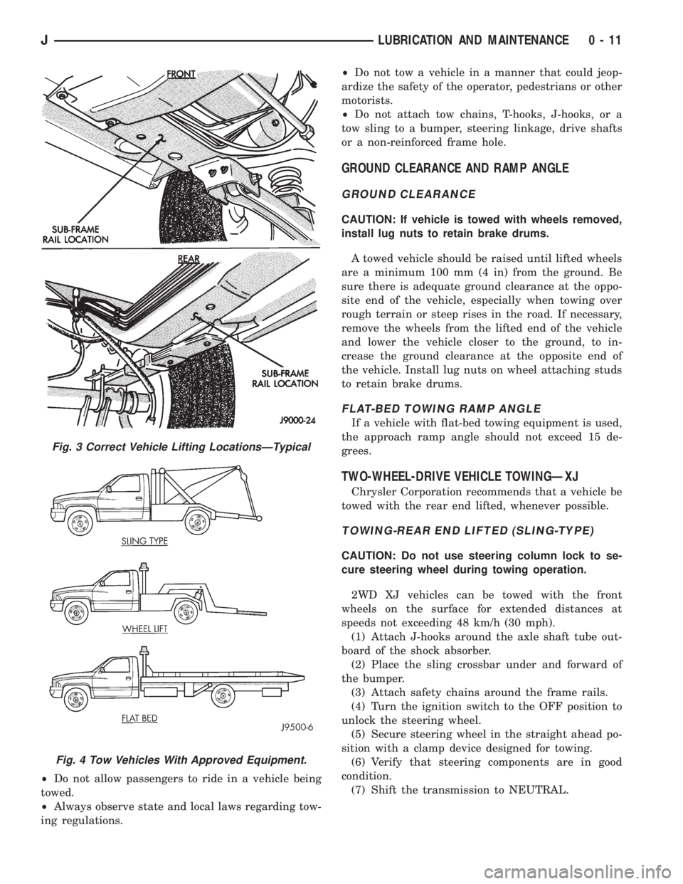
²Do not attach tow chains, T-hooks, J-hooks, or a
tow sling to a bumper, steering linkage, drive shafts
or a non-reinforced frame hole.
GROUND CLEARANCE AND RAMP ANGLE
GROUND CLEARANCE
CAUTION: If vehicle is towed with wheels removed,
install lug nuts to retain brake drums.
A towed vehicle should be raised until lifted wheels
are a minimum 100 mm (4 in) from the ground. Be
sure there is adequate ground clearance at the oppo-
site end of the vehicle, especially when towing over
rough terrain or steep rises in the road. If necessary,
remove the wheels from the lifted end of the vehicle
and lower the vehicle closer to the ground, to in-
crease the ground clearance at the opposite end of
the vehicle. Install lug nuts on wheel attaching studs
to retain brake drums.
FLAT-BED TOWING RAMP ANGLE
If a vehicle with flat-bed towing equipment is used,
the approach ramp angle should not exceed 15 de-
grees.
TWO-WHEEL-DRIVE VEHICLE TOWINGÐXJ
Chrysler Corporation recommends that a vehicle be
towed with the rear end lifted, whenever possible.
TOWING-REAR END LIFTED (SLING-TYPE)
CAUTION: Do not use steering column lock to se-
cure steering wheel during towing operation.
2WD XJ vehicles can be towed with the front
wheels on the surface for extended distances at
speeds not exceeding 48 km/h (30 mph).
(1) Attach J-hooks around the axle shaft tube out-
board of the shock absorber.
(2) Place the sling crossbar under and forward of
the bumper.
(3) Attach safety chains around the frame rails.
(4) Turn the ignition switch to the OFF position to
unlock the steering wheel.
(5) Secure steering wheel in the straight ahead po-
sition with a clamp device designed for towing.
(6) Verify that steering components are in good
condition.
(7) Shift the transmission to NEUTRAL.
Fig. 3 Correct Vehicle Lifting LocationsÐTypical
Fig. 4 Tow Vehicles With Approved Equipment.
JLUBRICATION AND MAINTENANCE 0 - 11