1995 JEEP XJ ratio
[x] Cancel search: ratioPage 43 of 2158
SPECIAL ADDITIVES
The addition of any special-type fluid to a Jeep au-
tomatic transmission is not recommended. The only
exception is the addition of black-light detection dye
to aid in detecting the source of ATF leaks. The use
of transmission sealing additives should also be
avoided.
Black-light detection dye is factory-installed
in automatic transmissions and, unless the ATF
has been drained and re-placed, it is not neces-
sary to add dye.
FLUID AND FILTER CHANGE
The automatic transmission fluid and filter should
be changed at the intervals described in the Mainte-
nance Schedules section of this Group. Refer to
Group 21, Transmission for proper service proce-
dures.
TRANSFER CASE (4WD VEHICLES)
The transfer case should be inspected for fluid
leaks and proper fluid level when other under vehicle
service is performed.
FLUID LEVEL
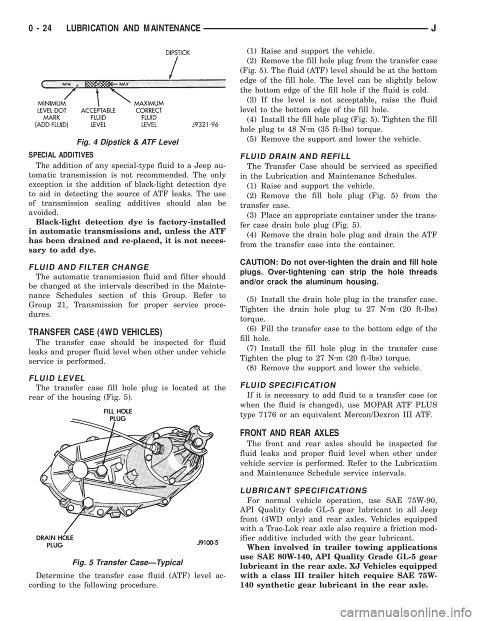
The transfer case fill hole plug is located at the
rear of the housing (Fig. 5).
Determine the transfer case fluid (ATF) level ac-
cording to the following procedure.(1) Raise and support the vehicle.
(2) Remove the fill hole plug from the transfer case
(Fig. 5). The fluid (ATF) level should be at the bottom
edge of the fill hole. The level can be slightly below
the bottom edge of the fill hole if the fluid is cold.
(3) If the level is not acceptable, raise the fluid
level to the bottom edge of the fill hole.
(4) Install the fill hole plug (Fig. 5). Tighten the fill
hole plug to 48 Nzm (35 ft-lbs) torque.
(5) Remove the support and lower the vehicle.
FLUID DRAIN AND REFILL
The Transfer Case should be serviced as specified
in the Lubrication and Maintenance Schedules.
(1) Raise and support the vehicle.
(2) Remove the fill hole plug (Fig. 5) from the
transfer case.
(3) Place an appropriate container under the trans-
fer case drain hole plug (Fig. 5).
(4) Remove the drain hole plug and drain the ATF
from the transfer case into the container.
CAUTION: Do not over-tighten the drain and fill hole
plugs. Over-tightening can strip the hole threads
and/or crack the aluminum housing.
(5) Install the drain hole plug in the transfer case.
Tighten the drain hole plug to 27 Nzm (20 ft-lbs)
torque.
(6) Fill the transfer case to the bottom edge of the
fill hole.
(7) Install the fill hole plug in the transfer case
Tighten the plug to 27 Nzm (20 ft-lbs) torque.
(8) Remove the support and lower the vehicle.
FLUID SPECIFICATION
If it is necessary to add fluid to a transfer case (or
when the fluid is changed), use MOPAR ATF PLUS
type 7176 or an equivalent Mercon/Dexron III ATF.
FRONT AND REAR AXLES
The front and rear axles should be inspected for
fluid leaks and proper fluid level when other under
vehicle service is performed. Refer to the Lubrication
and Maintenance Schedule service intervals.
LUBRICANT SPECIFICATIONS
For normal vehicle operation, use SAE 75W-90,
API Quality Grade GL-5 gear lubricant in all Jeep
front (4WD only) and rear axles. Vehicles equipped
with a Trac-Lok rear axle also require a friction mod-
ifier additive included with the gear lubricant.
When involved in trailer towing applications
use SAE 80W-140, API Quality Grade GL-5 gear
lubricant in the rear axle. XJ Vehicles equipped
with a class III trailer hitch require SAE 75W-
140 synthetic gear lubricant in the rear axle.
Fig. 4 Dipstick & ATF Level
Fig. 5 Transfer CaseÐTypical
0 - 24 LUBRICATION AND MAINTENANCEJ
Page 49 of 2158

FLUID LEVEL
The fluid level indicator (dipstick) is attached to
the reservoir cap (Fig. 6). The fluid level in the res-
ervoir can be determined with the fluid either hot or
cold.
(1) Remove the cap from the reservoir.
(2) Depending on fluid temperature, if the level is
below the FULL HOT mark or the FULL COLD
mark on the dipstick, add power steering fluid.
(3) Install the cap on the reservoir.CAUTION: Do not over fill power steering reservoir
when adding fluid, seal damage and leakage can re-
sult.
MANUAL STEERING GEAR
The manual steering gear should be inspected for
damage at the same time as the engine oil is
changed and the oil filter is replaced. Refer to Group
19, Steering for additional information and service
procedures.
POWER BRAKE SYSTEM
RECOMMENDED MAINTENANCE
The brake fluid level (Fig. 8) should be inspected
when other underhood service is done. With disc-
brakes, the fluid level can be expected to fall as the
brake pads wear. However, a low fluid level can also
be caused by a leak, and repair will then be neces-
sary. Refer to Group 5, Brakes for proper service pro-
cedures.
In addition, the brake system should be operation-
ally tested periodically to ensure that it is function-
ing normally.
FLUID SPECIFICATION
Jeep power brake systems require MOPAR Heavy-
Duty Brake Fluid, or an equivalent product identified
as conforming to FMVSS No. 116, DOT-3 and SAE
J-1703 specifications.
Use brake fluid from properly sealed container
when adding fluid to the reservoir. Never use re-
claimed fluid or fluid that does not conform to the
DOT/SAE Standards.
CAUTION: Use of a brake fluid that has a lower ini-
tial boiling point then specified by FMVSS No. 116,
DOT 3 and SAE J-1703 could result in sudden brake
failure during hard, prolonged braking.
Do not allow petroleum base fluids to contaminate
the brake fluid. Seal damage will result.
BRAKE FLUID LEVEL
STANDARD POWER BRAKE SYSTEM
(1) Clean the cover and the sides of the brake fluid
reservoir.
(2) Detach the bail retainer from the reservoir
cover and remove the cover from the reservoir.
(3) The brake fluid level should be 6 mm (1/4 in)
below the rim of each reservoir well for XJ and YJ
Vehicles (Fig. 7 and 8). If not, add brake fluid as nec-
essary.
(4) Inspect the reservoir cover bail retainer for ten-
sion and the cover for proper fit. The cover should fit
tight and have a good seal.
Fig. 5 Power Steering SystemÐYJ Vehicles
Fig. 6 Power Steering Fluid Reservoir DipstickÐ
Typical
0 - 30 LUBRICATION AND MAINTENANCEJ
Page 50 of 2158

(5) Inspect the reservoir rubber diaphragm seal for
cracks, cuts and distortion.
(6) Inspect the brake fluid tubing fittings and the
master cylinder housing for indications of fluid leak-
age. Repair as necessary.
(7) Install the brake fluid reservoir cover.
ANTI-LOCK BRAKE SYSTEMÐXJ VEHICLES
The anti-lock brake system fluid reservoir for XJ
Vehicles is located in the engine compartment at the
left side of the dash panel.
(1) Turn the ignition switch ON and allow the
pump motor to operate until it automatically de-en-
ergizes.
(2) Clean the cover before removing it.
CAUTION: Over-filling could cause fluid overflow
and possible reservoir damage when the pump mo-
tor energizes.
(3) The brake fluid level should be no lower than
the ADD indicator on the side of the reservoir (Fig.
8). If not, add brake fluid as necessary. Raise the
fluid level to the FULL indicator only. Do not over-fill
the reservoir.
(4) Turn the ignition switch OFF.
BRAKE SYSTEM INSPECTION
A brake system inspection should be included with
all brake service procedures, and also each time the
vehicle is lubricated.
(1) Inspect the brake pads and linings for excessive
wear, cracks, charred surfaces and broken rivets.
(2) Inspect brake pads and linings for contamina-
tion from brake fluid, and/or other fluids.
(3) Replace the brake pads linings if they are worn
to within 0.78 mm (1/32 in) of the rivet head.
(4) Operate the rear brake self-adjuster lever and
pivot. Test the operation of the self-adjuster screw for
ease of movement.
(5) Inspect the self-adjuster components for wear
or damage.
(6) Inspect the disc brake caliper dust boot for
damage and indications of brake fluid leakage. In-
spect the bushings and pins for corrosion, tears and a
binding condition.
(7) Pull the rear wheel cylinder dust boot back to
expose the wheel cylinder housing. Inspect for fluid
leaks. Inspect the pistons and cylinder bores.
(8) Inspect the brake differential warning valve
and housing for indications of leakage.
BRAKE FLUID HOSES/TUBING
The rubber brake fluid hoses should be inspected
for:
²Correct length
²Severe surface cracking
²Swelling
²Pulling
²Scuffing
²Excessively worn areas
If the hose has cracks or abrasions in the rub-
ber cover, the hose should be replaced.
(1) Inspect all the hoses for kinks, a distorted con-
dition and fluid leakage.
(2) Inspect the hose and tubing routing under the
vehicle. Verify that no hose/tubing is rubbing against
any exhaust or other underbody components.
PARKING BRAKE
(1) Engage the parking brake pedal and then re-
lease it.
(2) Test it for smooth operation and vehicle-holding
capability.
(3) Inspect the parking brake cables.
(4) With the parking brake released, the rear
wheels should
rotate without restriction. Adjust the parking brake
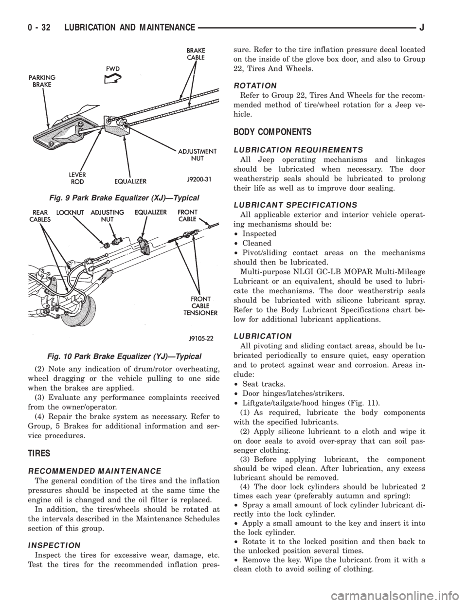
cable tension, if necessary (Fig. 9 and 10).
(5) Repair any parking brake malfunctions.
BRAKE OPERATIONAL TEST
(1) Drive the vehicle and test for proper brake ac-
tion.
Fig. 7 Reservoir Fluid LevelÐYJ (2.5L)
Fig. 8 Reservoir Fluid LevelÐYJ-XJ and Anti-Lock
Brake System
JLUBRICATION AND MAINTENANCE 0 - 31
Page 51 of 2158
(2) Note any indication of drum/rotor overheating,
wheel dragging or the vehicle pulling to one side
when the brakes are applied.
(3) Evaluate any performance complaints received
from the owner/operator.
(4) Repair the brake system as necessary. Refer to
Group, 5 Brakes for additional information and ser-
vice procedures.
TIRES
RECOMMENDED MAINTENANCE
The general condition of the tires and the inflation
pressures should be inspected at the same time the
engine oil is changed and the oil filter is replaced.
In addition, the tires/wheels should be rotated at
the intervals described in the Maintenance Schedules
section of this group.
INSPECTION
Inspect the tires for excessive wear, damage, etc.
Test the tires for the recommended inflation pres-sure. Refer to the tire inflation pressure decal located
on the inside of the glove box door, and also to Group
22, Tires And Wheels.
ROTATION
Refer to Group 22, Tires And Wheels for the recom-
mended method of tire/wheel rotation for a Jeep ve-
hicle.
BODY COMPONENTS
LUBRICATION REQUIREMENTS
All Jeep operating mechanisms and linkages
should be lubricated when necessary. The door
weatherstrip seals should be lubricated to prolong
their life as well as to improve door sealing.
LUBRICANT SPECIFICATIONS
All applicable exterior and interior vehicle operat-
ing mechanisms should be:
²Inspected
²Cleaned
²Pivot/sliding contact areas on the mechanisms
should then be lubricated.
Multi-purpose NLGI GC-LB MOPAR Multi-Mileage
Lubricant or an equivalent, should be used to lubri-
cate the mechanisms. The door weatherstrip seals
should be lubricated with silicone lubricant spray.
Refer to the Body Lubricant Specifications chart be-
low for additional lubricant applications.
LUBRICATION
All pivoting and sliding contact areas, should be lu-
bricated periodically to ensure quiet, easy operation
and to protect against wear and corrosion. Areas in-
clude:
²Seat tracks.
²Door hinges/latches/strikers.
²Liftgate/tailgate/hood hinges (Fig. 11).
(1) As required, lubricate the body components
with the specified lubricants.
(2) Apply silicone lubricant to a cloth and wipe it
on door seals to avoid over-spray that can soil pas-
senger clothing.
(3) Before applying lubricant, the component
should be wiped clean. After lubrication, any excess
lubricant should be removed.
(4) The door lock cylinders should be lubricated 2
times each year (preferably autumn and spring):
²Spray a small amount of lock cylinder lubricant di-
rectly into the lock cylinder.
²Apply a small amount to the key and insert it into
the lock cylinder.
²Rotate it to the locked position and then back to
the unlocked position several times.
²Remove the key. Wipe the lubricant from it with a
clean cloth to avoid soiling of clothing.
Fig. 9 Park Brake Equalizer (XJ)ÐTypical
Fig. 10 Park Brake Equalizer (YJ)ÐTypical
0 - 32 LUBRICATION AND MAINTENANCEJ
Page 53 of 2158
FRONT SUSPENSION AND AXLE
CONTENTS
page page
AXLE NOISE/VIBRATION DIAGNOSIS........ 18
AXLE SPECIFICATIONS................... 49
FRONT WHEEL ALIGNMENT................ 5
GENERAL INFORMATION.................. 1MODEL 30 AXLE AND TUBE AXLE (2WD).... 22
TORQUE SPECIFICATIONS................ 49
XJ FRONT SUSPENSION.................. 11
YJ FRONT SUSPENSION.................. 15
GENERAL INFORMATION
FRONT SUSPENSION
XJ VEHICLES
The XJ front suspension is a link/coil design. This
suspension is use on Left Hand Drive (LHD) and
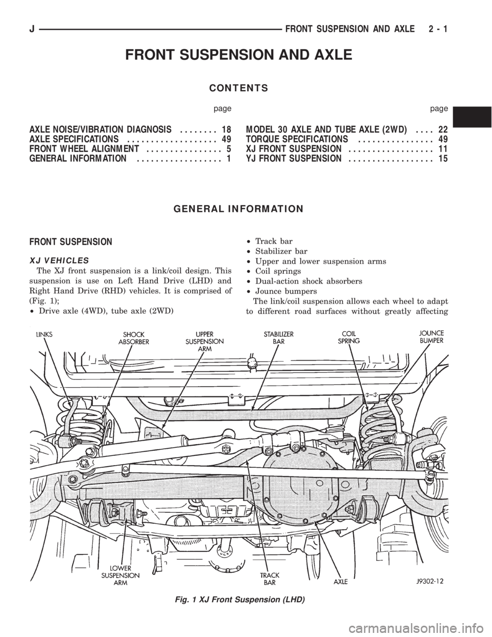
Right Hand Drive (RHD) vehicles. It is comprised of
(Fig. 1);
²Drive axle (4WD), tube axle (2WD)²Track bar
²Stabilizer bar
²Upper and lower suspension arms
²Coil springs
²Dual-action shock absorbers
²Jounce bumpers
The link/coil suspension allows each wheel to adapt
to different road surfaces without greatly affecting
Fig. 1 XJ Front Suspension (LHD)
JFRONT SUSPENSION AND AXLE 2 - 1
Page 55 of 2158
spring and axle travel (jounce or rebound) is limited
through use of rubber bumpers mounted on the
frame.
Suspension components which use rubber bushings
should be tightened at vehicle ride height. This will
prevent premature failure of the bushing and main-
tain ride comfort. The bushings should never be lu-
bricated.
The shocks absorbers dampen jounce and rebound
of the vehicle over various road conditions. The top of
the shock absorbers bolt to the frame. The bottom of
the shocks bolt to the axle brackets.
The stabilizer bar is used to minimize vehicle front
sway during turns. The spring steel bar helps control
vehicle body in relationship to the suspension move-
ment. The bar extends across the front underside of
the chassis and connects to the frame rails. Links
connect the bar to the axle brackets. Stabilizer bar
mounts are isolated by rubber bushings.
The track bar is used to minimize front axle side-
to-side movement. The track bar is attached to a
frame rail bracket and axle bracket. The bar uses
bushings at both ends.
FRONT DRIVE AXLE
It is not necessary to remove the complete axle
from the vehicle for routine differential service. If the
differential housing or axle shaft tubes are damaged,
the complete axle assembly can be removed and ser-
viced.
For complete drive axle assembly removal and in-
stallation refer to Drive Axle Assembly Replacement
in this Group.
The removable cover provides for servicing without
removing axle from vehicle.
The integral type housing, hypoid gear design has
the centerline of the pinion set above the centerline
of the ring gear.
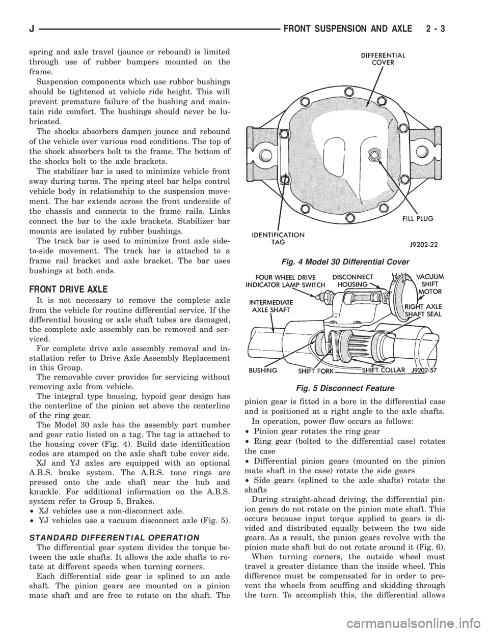
The Model 30 axle has the assembly part number
and gear ratio listed on a tag. The tag is attached to
the housing cover (Fig. 4). Build date identification
codes are stamped on the axle shaft tube cover side.
XJ and YJ axles are equipped with an optional
A.B.S. brake system. The A.B.S. tone rings are
pressed onto the axle shaft near the hub and
knuckle. For additional information on the A.B.S.
system refer to Group 5, Brakes.
²XJ vehicles use a non-disconnect axle.
²YJ vehicles use a vacuum disconnect axle (Fig. 5).
STANDARD DIFFERENTIAL OPERATION
The differential gear system divides the torque be-
tween the axle shafts. It allows the axle shafts to ro-
tate at different speeds when turning corners.
Each differential side gear is splined to an axle
shaft. The pinion gears are mounted on a pinion
mate shaft and are free to rotate on the shaft. Thepinion gear is fitted in a bore in the differential case
and is positioned at a right angle to the axle shafts.
In operation, power flow occurs as follows:
²Pinion gear rotates the ring gear
²Ring gear (bolted to the differential case) rotates
the case
²Differential pinion gears (mounted on the pinion
mate shaft in the case) rotate the side gears
²Side gears (splined to the axle shafts) rotate the
shafts
During straight-ahead driving, the differential pin-
ion gears do not rotate on the pinion mate shaft. This
occurs because input torque applied to gears is di-
vided and distributed equally between the two side
gears. As a result, the pinion gears revolve with the
pinion mate shaft but do not rotate around it (Fig. 6).
When turning corners, the outside wheel must
travel a greater distance than the inside wheel. This
difference must be compensated for in order to pre-
vent the wheels from scuffing and skidding through
the turn. To accomplish this, the differential allows
Fig. 4 Model 30 Differential Cover
Fig. 5 Disconnect Feature
JFRONT SUSPENSION AND AXLE 2 - 3
Page 56 of 2158
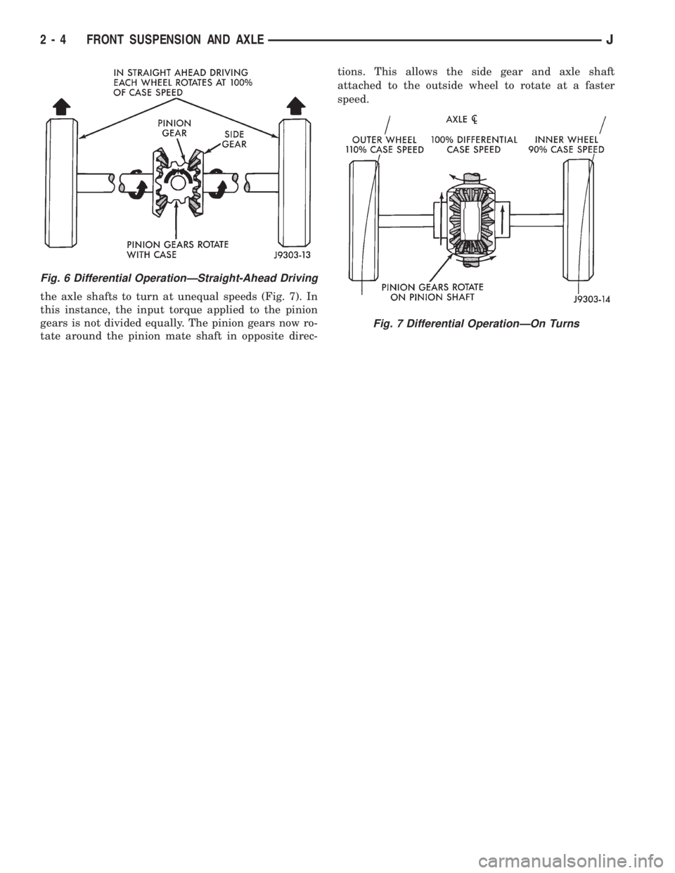
the axle shafts to turn at unequal speeds (Fig. 7). In
this instance, the input torque applied to the pinion
gears is not divided equally. The pinion gears now ro-
tate around the pinion mate shaft in opposite direc-tions. This allows the side gear and axle shaft
attached to the outside wheel to rotate at a faster
speed.
Fig. 6 Differential OperationÐStraight-Ahead Driving
Fig. 7 Differential OperationÐOn Turns
2 - 4 FRONT SUSPENSION AND AXLEJ
Page 57 of 2158
FRONT WHEEL ALIGNMENT
INDEX
page page
Alignment Measurements and Adjustments....... 8
General Information........................ 5Pre-Alignment Inspection.................... 6
GENERAL INFORMATION
Front wheel alignment involves the correct posi-
tioning of the wheels in relation to the vehicle. The
positioning is accomplished through suspension and
steering linkage adjustments. An alignment is con-
sidered essential for efficient steering, good direc-
tional stability and to maximize tire wear. The most
important measurements of front end alignment are
caster, camber and toe position.
Routine inspection of the front suspension
and steering components is a good preventative
maintenance practice. Inspection also helps to
ensure safe operation of the vehicle.
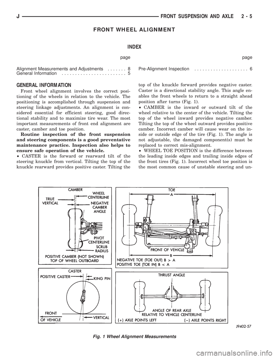
²CASTER is the forward or rearward tilt of the
steering knuckle from vertical. Tilting the top of the
knuckle rearward provides positive caster. Tilting thetop of the knuckle forward provides negative caster.
Caster is a directional stability angle. This angle en-
ables the front wheels to return to a straight ahead
position after turns (Fig. 1).
²CAMBER is the inward or outward tilt of the
wheel relative to the center of the vehicle. Tilting the
top of the wheel inward provides negative camber.
Tilting the top of the wheel outward provides positive
camber. Incorrect camber will cause wear on the in-
side or outside edge of the tire (Fig. 1). The angle is
not adjustable, the damaged component(s) must be
replaced to correct mis-alignment.
²WHEEL TOE POSITION is the difference between
the leading inside edges and trailing inside edges of
the front tires (Fig. 1). Incorrect wheel toe position is
the most common cause of unstable steering and un-
Fig. 1 Wheel Alignment Measurements
JFRONT SUSPENSION AND AXLE 2 - 5