1995 JEEP XJ ratio
[x] Cancel search: ratioPage 70 of 2158

AXLE NOISE/VIBRATION DIAGNOSIS
INDEX
page page
Driveline Snap........................... 19
Gear and Bearing Noise.................... 18
General Information....................... 18Low Speed Knock......................... 19
Vibration................................ 19
GENERAL INFORMATION
Axle bearing problem conditions are usually caused
by:
²Insufficient or incorrect lubricant
²Foreign matter/water contamination
²Incorrect bearing preload torque adjustment
²Incorrect backlash (to tight)
When serviced, the bearings must be cleaned thor-
oughly. They should be dried with lint-free shop tow-
els.Never dry bearings with compressed air.
This will overheat them and brinell the bearing
surfaces. This will result in noisy operation af-
ter repair.
Axle gear problem conditions are usually the result
of:
²Insufficient lubrication
²Incorrect or contaminated lubricant
²Overloading (excessive engine torque) or exceeding
vehicle weight capacity
²Incorrect clearance or backlash adjustment
Insufficient lubrication is usually the result of a
housing cover leak. It can also be from worn axle
shaft or pinion gear seals. Check for cracks or porous
areas in the housing or tubes.
Using the wrong lubricant will cause overheating
and gear failure. Gear tooth cracking and bearing
spalling are indicators of this.
Axle component breakage is most often the result
of:
²Severe overloading
²Insufficient lubricant
²Incorrect lubricant
²Improperly tightened components
Overloading occurs when towing heavier than rec-
ommended loads. Component breakage can occur
when the wheels are spun excessively. Incorrect lu-
bricant quantity contributes to breakage. Loose dif-
ferential components can also cause breakage.
Incorrect bearing preload or gear backlash will not
result in component breakage. Mis-adjustment will
produce enough noise to cause service repair before a
failure occurs. If a mis-adjustment condition is not
corrected, component failure can result.
Excessive bearing preload may not be noisy. This
condition will cause high temperature which can re-
sult in bearing failure.
GEAR AND BEARING NOISE
GEAR NOISE
Axle gear noise can be caused by insufficient lubri-
cant. Incorrect backlash, tooth contact, or worn/dam-
aged gears can cause noise.
Gear noise usually happens at a specific speed
range. The range is 30 to 40 mph, or above 50 mph.
The noise can also occur during a specific type of
driving condition. These conditions are acceleration,
deceleration, coast, or constant load.
When road testing, accelerate the vehicle to the
speed range where the noise is the greatest. Shift
out-of-gear and coast through the peak-noise range.
If the noise stops or changes greatly, check for insuf-
ficient lubricant. Incorrect ring gear backlash, or
gear damage can cause noise changes.
Differential side and pinion gears can be checked
by turning the vehicle. They usually do not cause
noise in straight-ahead driving. These gears are
loaded during vehicle turns. If noise does occur dur-
ing vehicle turns, the side or pinion gears could be
worn or damaged. A worn pinion gear mate shaft can
also cause a snapping or a knocking noise.
BEARING NOISE
The axle shaft, differential and pinion gear bear-
ings can all produce noise when worn or damaged.
Bearing noise can be either a whining, or a growling
sound.
Pinion gear bearings have a constant-pitch noise.
This noise changes only with vehicle speed. Pinion
bearing noise will be higher because it rotates at a
faster rate. Drive the vehicle and load the differen-
tial. If bearing noise occurs the pinion rear bearing is
the source of the noise. If the bearing noise is heard
during a coast, front bearing is the source.
Worn, damaged differential bearings usually pro-
duce a low pitch noise. Differential bearing noise is
similar to pinion bearing. The pitch of differential
bearing noise is also constant and varies only with
vehicle speed.
2 - 18 FRONT SUSPENSION AND AXLEJ
Page 71 of 2158
Axle shaft bearings produce noise and vibration
when worn or damaged. The noise generally changes
when the bearings are loaded. Road test the vehicle.
Turn the vehicle sharply to the left and to the right.
This will load the bearings and change the noise
level. Where axle bearing damage is slight, the noise
is usually not noticeable at speeds above 30 mph.
LOW SPEED KNOCK
Low speed knock is generally caused by a worn U-
joint or by worn side-gear thrust washers. A worn
pinion gear shaft bore will also cause low speed
knock.
VIBRATION
Vibration at the rear of the vehicle is usually
caused by a:
²Damaged drive shaft
²Missing drive shaft balance weight
²Worn, out-of-balance wheels
²Loose wheel lug nuts
²Worn U-joint
²Loose spring U-bolts
²Loose/broken springs
²Damaged axle shaft bearings
²Loose pinion gear nut
²Excessive pinion yoke run out²Bent axle shaft
Check for loose or damaged front-end components
or engine/transmission mounts. These components
can contribute to what appears to be a rear-end vi-
bration. Do not overlook engine accessories, brackets
and drive belts.
All driveline components should be examined be-
fore starting any repair.
Refer to Group 22ÐTires And Wheels for addi-
tional information involving vibration diagnosis.
DRIVELINE SNAP
A snap or clunk noise when the vehicle is shifted
into gear (or the clutch engaged), can be caused by:
²High engine idle speed
²Loose engine/transmission/transfer case mounts
²Worn U-joints
²Loose spring mounts
²Loose pinion gear nut and yoke
²Excessive ring gear backlash
²Excessive differential side gear-to-case clearance
The source of a snap or a clunk noise can be deter-
mined with the assistance of a helper. Raise the ve-
hicle on a hoist with the wheels free to rotate.
Instruct the helper to shift the transmission into
gear. Listen for the noise, a mechanics stethoscope is
helpful in isolating the source of a noise.
JFRONT SUSPENSION AND AXLE 2 - 19
Page 74 of 2158

MODEL 30 AXLE AND TUBE AXLE (2WD)
INDEX
page page
Axle Bushing Replacement.................. 34
Axle ShaftÐCardan U-Joint.................. 26
Backlash and Contact Pattern Analysis......... 45
Cleaning/Inspection........................ 37
Differential and Pinion Measurement........... 40
Differential Assembly....................... 38
Differential Disassembly.................... 35
Differential Installation...................... 44
Differential Removal....................... 34
Differential Shim Pack Measurement and
Adjustment............................ 43
Drive Axle Assembly ReplacementÐXJ Vehicles . . 23
Drive Axle Assembly ReplacementÐYJ Vehicles . . 24Final Assembly........................... 46
Hub Bearing and Axle Shaft................. 25
Information.............................. 22
Inner Axle Shaft Oil Seal Replacement......... 35
Lubricant Change......................... 23
Lubricant Specifications..................... 22
Pinion Gear Assembly/Installation............. 42
Pinion Gear Depth Information............... 39
Pinion Removal/Disassembly................. 36
Pinion Seal Replacement................... 25
Steering Knuckle and Ball Studs.............. 32
Vacuum Disconnect AxleÐYJ Vehicles......... 27
INFORMATION
The Model 30 front axles consists of a cast iron dif-
ferential housing with axle shaft tubes extending
from either side. The tubes are pressed into the dif-
ferential housing and welded.
The integral type housing, hypoid gear design has
the centerline of the pinion set above the centerline
of the ring gear.
The axle has a fitting for a vent hose used to re-
lieve internal pressure caused by lubricant vaporiza-
tion and internal expansion.
The axles are equipped with semi-floating axle
shafts, meaning that loads are supported by the hub
bearings. The axle shafts are retained by nuts at the
hub bearings. The hub bearings are bolted to the
steering knuckle at the outboard end of the axle tube
yoke. The hub bearings are serviced as an assembly.
The axles are equipped with ABS brake sensors.
The sensors are attached to the knuckle assemblies
and tone rings are pressed on the axle shaft.Use
care when removing axle shafts as NOT to dam-
age the tone wheel or the sensor.
The stamped steel cover provides a means for in-
spection and servicing the differential.
The Model 30 axle has the assembly part number
and gear ratio listed on a tag. The tag is attached to
the housing cover. Build date identification codes are
stamped on the axle shaft tube cover side.
The differential case is a one-piece design. The dif-
ferential pinion mate shaft is retained with a roll
pin. Differential bearing preload and ring gear back-
lash is adjusted by the use of shims (select thick-
ness). The shims are located between the differential
bearing cones and case. Pinion bearing preload is set
and maintained by the use of collapsible spacer.
COMMAND-TRACÐYJ VEHICLES
The Command-Trac system is a vacuum disconnect
axle. The system has a two-piece axle shaft coupled
together by a shift collar. For two-wheel drive opera-
tion, the vacuum motor and shift fork disengages the
axle shaft splines. For four-wheel drive operation, the
vacuum motor and shift fork engages the axle
splines.
SELEC-TRACÐXJ VEHICLES
The Selec-Trac system is a non-disconnect axle.
Shifting from two-wheel to four-wheel drive is done
at the transfer case.
For XJ vehicles equipped withSelec-Tracand
ABS brake system, refer to Group 5ÐBrakes for ad-
ditional service information.
LUBRICANT SPECIFICATIONS
Multi-purpose, hypoid gear lubricant should be
used for Model 30 axles. The lubricant should have
MIL-L-2105C and API GL 5 quality specifications.
MOPARtHypoid Gear Lubricant conforms to both of
these specifications.
²The factory fill for the Model 30 axle is SAE Ther-
mally Stable 80W-90 gear lubricant.Do not use
heavier weight lubricant, this will cause axle
engagement difficulties.
²The factory installed lubricant quantity for the
NON-DISCONNECT TYPE AXLE is 1.48 L (3.13
pts.).
²The factory installed lubricant quantity for the
VACUUM-DISCONNECT TYPE AXLE is 1.65 L (3.76
pts.).
Refer to Group 0, Lubrication and Maintenance for
additional information regarding temperature range,
viscosity and fluid level.
2 - 22 FRONT SUSPENSION AND AXLEJ
Page 101 of 2158

AXLE SPECIFICATIONS
MODEL 30 FRONT AXLE
Axle Type........................................................Hypoid
Lubricant................SAE Thermally Stable 80W-90
Lube Capacity
YJ .....................................................1.65 L (3.76 pts.)
XJ .....................................................1.48 L (3.13 pts.)
Axle Ratio...................................3.07 3.55 3.73 4.10
DifferentialSide Gear Clearance .0.12-0.20mm (0.005-0.008 in.)
Ring Gear
Diameter .....................................18.09 cm (7.125 in.)
Backlash.........................0-0.15 mm (0.005-0.008 in.)
Pinion Std. Depth...................92.1 mm (3.625 in.)
Pinion Bearing Preload
Original Bearing ..................1-2 Nzm (10-20 in. lbs.)
New Bearing ......................1.5-4 Nzm (15-35 in. lbs.)
TORQUE SPECIFICATIONS
XJ FRONT SUSPENSION COMPONENTS
DESCRIPTION ................................................TORQUE
Shock Absorber
Upper Nut ......................................11 Nzm (8 ft. lbs.)
Lower Nut ....................................23 Nzm (17 ft. lbs.)
Suspension Arm Upper
Front Nut .....................................74 Nzm (55 ft. lbs.)
Rear Nut ......................................89 Nzm (66 ft. lbs.)
Suspension Arm Lower
Front and Rear Nut ..................115 Nzm (85 ft. lbs.)
Stabilizer Bar
Clamp Bolt ...................................54 Nzm (40 ft. lbs.)
Link Upper Nut ..........................36 Nzm (27 ft. lbs.)
Link Lower Nut ..........................95 Nzm (70 ft. lbs.)
Track Bar
Ball Stud Nut ..............................81 Nzm (60 ft. lbs.)
Axle Bracket Bolt ......................100 Nzm (74 ft. lbs.)
Track Bar Bracket
Bolts............................................125 Nzm (92 ft. lbs.)
Nut ..............................................100 Nzm (74 ft. lbs.)
Support Bolts ...............................42 Nzm (31 ft. lbs.)
YJ FRONT SUSPENSION COMPONENTS
DESCRIPTION ................................................TORQUE
Shock Absorber
Upper Nut ......................................13 Nzm (9 ft. lbs.)Lower Nut ....................................61 Nzm (45 ft. lbs.)
Stabilizer Bar
Clamp Bolt ...................................41 Nzm (30 ft. lbs.)
Link Nut ......................................61 Nzm (45 ft. lbs.)
Track Bar
Frame Bracket Nut.................142 Nzm (105 ft. lbs.)
Axle Bracket Nut ......................100 Nzm (74 ft. lbs.)
Spring
U-Bolt Nut .................................122 Nzm (90 ft. lbs.)
Front Shackle Bolt ..................135 Nzm (100 ft. lbs.)
Rear Pivot Bolt........................142 Nzm (105 ft. lbs.)
MODEL 30 AXLE
DESCRIPTION ................................................TORQUE
Fill Hole Plug...........................34 Nzm (25 ft. lbs.)
Diff. Cover Bolt........................41 Nzm (30 ft. lbs.)
Bearing Cap Bolt.....................61 Nzm (45 ft. lbs.)
Ring Gear Bolt.............95-122 Nzm (70-90 ft. lbs.)
Shift Motor Bolt.........................11 Nzm (8 ft. lbs.)
Axle Nut.................................237 Nzm (175 ft. lbs.)
Wheel Brg. Bolt......................102 Nzm (75 ft. lbs.)
Lower Ball Stud.....................108 Nzm (80 ft. lbs.)
Upper Ball Stud.....................101 Nzm (75 ft. lbs.)
ABS Sensor Bolt......................11 Nzm (96 in. lbs.)
JFRONT SUSPENSION AND AXLE 2 - 49
Page 102 of 2158
REAR SUSPENSION AND AXLES
CONTENTS
page page
8 1/4 AXLE............................ 30
AXLE NOISE/VIBRATION DIAGNOSIS......... 9
AXLE SPECIFICATIONS................... 51
GENERAL INFORMATION.................. 1
MODEL 35 AXLE........................ 13TORQUE SPECIFICATIONS................ 51
TRAC-LOK DIFFERENTIAL................. 45
XJ SUSPENSION......................... 3
YJ SUSPENSION......................... 6
GENERAL INFORMATION
SUSPENSION COMPONENTS
The Jeep rear suspension is comprised of;
²Drive axle
²Leaf springs
²Dual-action shock absorbers
²Track bar (YJ vehicles)
²Stabilizer bar (XJ vehicles)
²Jounce bumpers
The rear suspension design uses semi-elliptic
multi-leaf springs and a solid drive axle. The forward
end of the springs are mounted to the frame rail
hangers through rubber bushings. The bushings iso-
late road noise as the springs move. The rearward
end of the springs are attached to the frame by the
use of shackles. Again the spring and shackles use
rubber bushings to isolate road noise. The shackles
allow the springs to change their length as the vehi-
cle moves over various road conditions. The spring
and axle travel is limited through the use of bumpers
mounted on frame.
All suspension components that use bushings
should be tightened with the vehicle at normal ride
height. If the springs are not at normal ride position,
vehicle ride comfort could be affected. Rubber bush-
ings must never be lubricated.
The springs are attached to the axle pads with U-
bolts and plates. The springs use a center bolt that
holds the spring leafs in position. The bolt is also
used to locate the spring assembly to the axle pad.
Ride control is accomplished through the use of du-
al-action shock absorbers. The shocks dampen the
jounce and rebound as the vehicle travels over vari-
ous road conditions. The top of shock absorbers are
bolted to the frame bracket. The bottom of the shocks
are bolted to the axle bracket.
The stabilizer bar on the XJ is used to minimize
vehicle rear sway during turns. The bar helps the ve-
hicle maintain a flat attitude to the road surface. The
bar extends across the underside of the chassis and
connects to the frame rails. The links are connectedto the axle brackets. All mounting points of the sta-
bilizer bar are isolated by bushings.
The track bar on the YJ is used to minimize rear
axle side-to-side movement. The track bar is attached
to the frame rail bracket and axle bracket and is iso-
lated with bushings.
The jounce bumpers are used to limit the jounce
and rebound travel of the suspension.
AXLES
The Model 35 axle is standard for XJ and YJ vehi-
cles. The 8 1/4 axle is available in XJ vehicles with-
out ABS brakes.
The Model 35 and 8 1/4 axle housings has a cast
iron center section. Two steel axle shaft tubes are
pressed into the differential housing and welded.
It is not necessary to remove the axle from the ve-
hicle for service. A removable differential cover is
provided for routine vehicle service. If the differential
housing is damaged, the complete axle assembly can
be removed.
For complete drive axle assembly removal and in-
stallation refer to Drive Axle Assembly Replacement
in this Group.
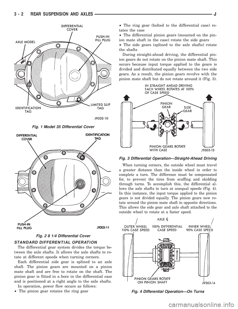
IDENTIFICATION
Model 35 axle has the assembly part number and
gear ratio listed on a tag. The tag is attached to the left
side of the housing cover (Fig. 1). Build date identifica-
tion codes on axles are stamped on the axle shaft tube
cover side. The Model 35 axle has a flat housing cover
gasket flange at the outer edge (Fig. 1).
The 8 1/4 axle has the build date code and gear ra-
tio tags attached to the housing cover (Fig. 2). The
housing cover gasket has a rolled gasket flange at
the outer edge (Fig. 2).
²The Model 35 axle has shaft tubes that are 2.625
inch (66.67 mm) in diameter.
²The 8 1/4 axle has axle shaft tubes that are 3.0-
inch (76.2 mm) in diameter.
JREAR SUSPENSION AND AXLES 3 - 1
Page 103 of 2158
STANDARD DIFFERENTIAL OPERATION
The differential gear system divides the torque be-
tween the axle shafts. It allows the axle shafts to ro-
tate at different speeds when turning corners.
Each differential side gear is splined to an axle
shaft. The pinion gears are mounted on a pinion
mate shaft and are free to rotate on the shaft. The
pinion gear is fitted in a bore in the differential case
and is positioned at a right angle to the axle shafts.
In operation, power flow occurs as follows:
²The pinion gear rotates the ring gear²The ring gear (bolted to the differential case) ro-
tates the case
²The differential pinion gears (mounted on the pin-
ion mate shaft in the case) rotate the side gears
²The side gears (splined to the axle shafts) rotate
the shafts
During straight-ahead driving, the differential pin-
ion gears do not rotate on the pinion mate shaft. This
occurs because input torque applied to the gears is
divided and distributed equally between the two side
gears. As a result, the pinion gears revolve with the
pinion mate shaft but do not rotate around it (Fig. 3).
When turning corners, the outside wheel must travel
a greater distance than the inside wheel in order to
complete a turn. The difference must be compensated
for, to prevent the tires from scuffing and skidding
through turns. To accomplish this, the differential al-
lows the axle shafts to turn at unequal speeds (Fig. 4).
In this instance, the input torque applied to the pinion
gears is not divided equally. The pinion gears now ro-
tate around the pinion mate shaft in opposite directions.
This allows the side gear and axle shaft attached to the
outside wheel to rotate at a faster speed.
Fig. 4 Differential OperationÐOn Turns
Fig. 1 Model 35 Differential Cover
Fig. 2 8 1/4 Differential Cover
Fig. 3 Differential OperationÐStraight-Ahead Driving
3 - 2 REAR SUSPENSION AND AXLESJ
Page 104 of 2158
XJ SUSPENSION
INDEX
page page
Leaf Spring............................... 4
Leaf Spring Eye Bushing Replacement.......... 5
Shock Absorber........................... 4Spring and Shock Diagnosis.................. 3
Stabilizer Bar............................. 5
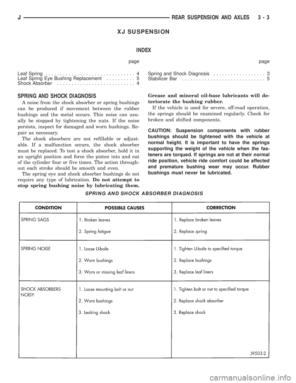
SPRING AND SHOCK DIAGNOSIS
A noise from the shock absorber or spring bushings
can be produced if movement between the rubber
bushings and the metal occurs. This noise can usu-
ally be stopped by tightening the nuts. If the noise
persists, inspect for damaged and worn bushings. Re-
pair as necessary.
The shock absorbers are not refillable or adjust-
able. If a malfunction occurs, the shock absorber
must be replaced. To test a shock absorber, hold it in
an upright position and force the piston into and out
of the cylinder four or five times. The action through-
out each stroke should be smooth and even.
The spring eye and shock absorber bushings do not
require any type of lubrication.Do not attempt to
stop spring bushing noise by lubricating them.Grease and mineral oil-base lubricants will de-
teriorate the bushing rubber.
If the vehicle is used for severe, off-road operation,
the springs should be examined regularly. Check for
broken and shifted components.
CAUTION: Suspension components with rubber
bushings should be tightened with the vehicle at
normal height. It is important to have the springs
supporting the weight of the vehicle when the fas-
teners are torqued. If springs are not at their normal
ride position, vehicle ride comfort could be affected
and premature bushing wear may occur. Rubber
bushings must never be lubricated.
SPRING AND SHOCK ABSORBER DIAGNOSIS
JREAR SUSPENSION AND AXLES 3 - 3
Page 107 of 2158
YJ SUSPENSION
INDEX
page page
Leaf Spring............................... 7
Leaf Spring Eye Bushing Replacement.......... 7
Shock Absorber........................... 7Spring and Shock Diagnosis.................. 6
Track Bar................................ 8
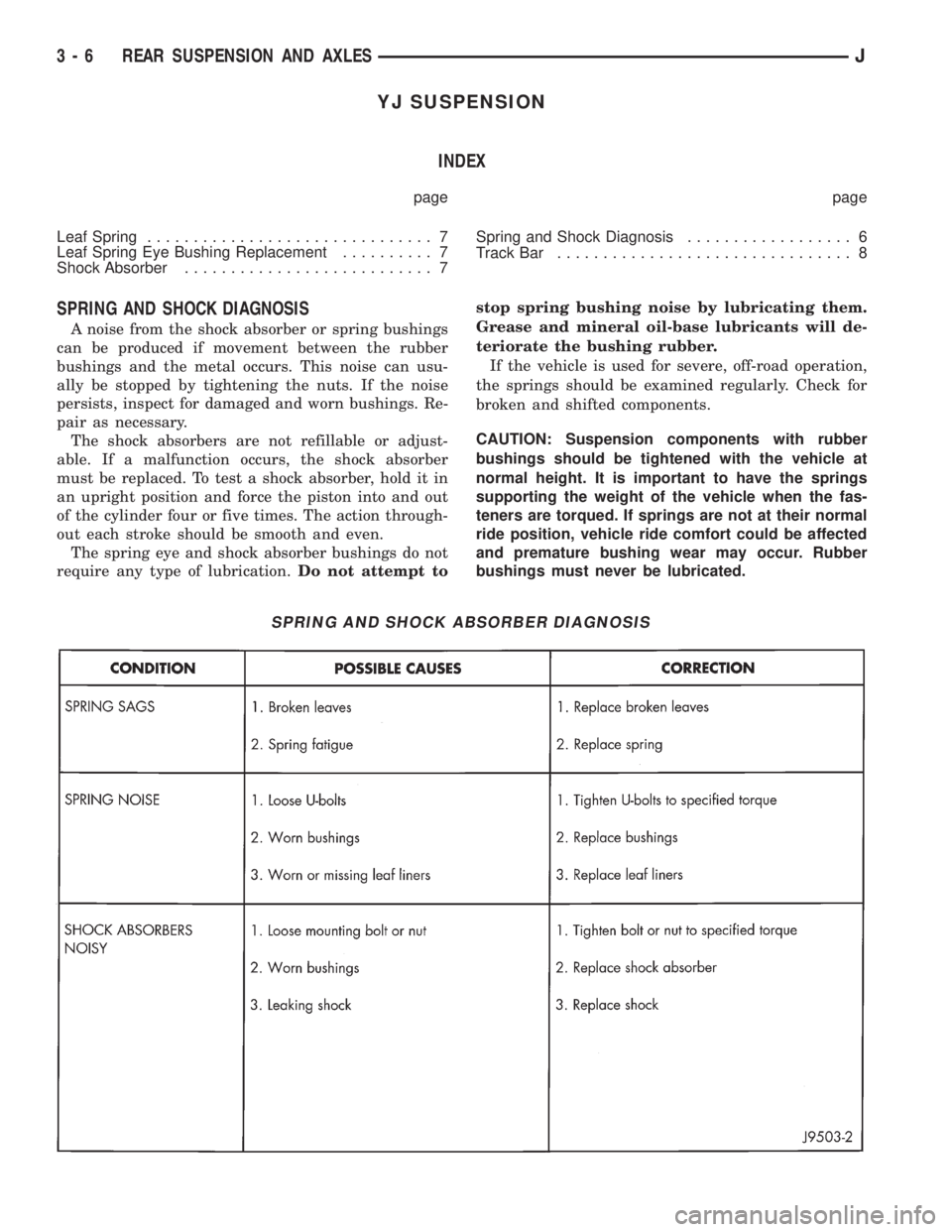
SPRING AND SHOCK DIAGNOSIS
A noise from the shock absorber or spring bushings
can be produced if movement between the rubber
bushings and the metal occurs. This noise can usu-
ally be stopped by tightening the nuts. If the noise
persists, inspect for damaged and worn bushings. Re-
pair as necessary.
The shock absorbers are not refillable or adjust-
able. If a malfunction occurs, the shock absorber
must be replaced. To test a shock absorber, hold it in
an upright position and force the piston into and out
of the cylinder four or five times. The action through-
out each stroke should be smooth and even.
The spring eye and shock absorber bushings do not
require any type of lubrication.Do not attempt tostop spring bushing noise by lubricating them.
Grease and mineral oil-base lubricants will de-
teriorate the bushing rubber.
If the vehicle is used for severe, off-road operation,
the springs should be examined regularly. Check for
broken and shifted components.
CAUTION: Suspension components with rubber
bushings should be tightened with the vehicle at
normal height. It is important to have the springs
supporting the weight of the vehicle when the fas-
teners are torqued. If springs are not at their normal
ride position, vehicle ride comfort could be affected
and premature bushing wear may occur. Rubber
bushings must never be lubricated.
SPRING AND SHOCK ABSORBER DIAGNOSIS
3 - 6 REAR SUSPENSION AND AXLESJ