1995 JEEP XJ Exhaust
[x] Cancel search: ExhaustPage 1408 of 2158
FUEL PRESSURE RELEASE PROCEDURE
WARNING: THE FUEL SYSTEM IS UNDER CON-
STANT FUEL PRESSURE (EVEN WITH THE ENGINE
OFF) OF APPROXIMATELY 131-269 KPA (19-39 PSI).
THIS PRESSURE MUST BE RELEASED BEFORE
SERVICING ANY FUEL SUPPLY OR FUEL RETURN
SYSTEM COMPONENT.
(1) Disconnect negative battery cable.
(2) Remove fuel tank filler neck cap to release fuel
tank pressure.
WARNING: DO NOT ALLOW FUEL TO SPILL ONTO
THE ENGINE INTAKE OR EXHAUST MANIFOLDS.
PLACE SHOP TOWELS UNDER AND AROUND THE
PRESSURE PORT TO ABSORB FUEL WHEN THE
PRESSURE IS RELEASED FROM THE FUEL RAIL.
WARNING: WEAR PROPER EYE PROTECTION
WHEN RELEASING FUEL SYSTEM PRESSURE.
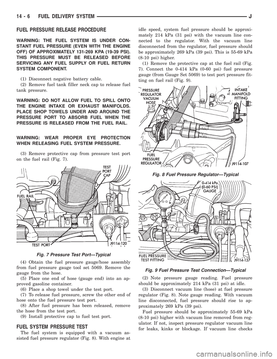
(3) Remove protective cap from pressure test port
on the fuel rail (Fig. 7).
(4) Obtain the fuel pressure gauge/hose assembly
from fuel pressure gauge tool set 5069. Remove the
gauge from the hose.
(5) Place one end of hose (gauge end) into an ap-
proved gasoline container.
(6) Place a shop towel under the test port.
(7) To release fuel pressure, screw the other end of
hose onto the fuel pressure test port.
(8) After fuel pressure has been released, remove
the hose from the test port.
(9) Install protective cap to fuel test port.
FUEL SYSTEM PRESSURE TEST
The fuel system is equipped with a vacuum as-
sisted fuel pressure regulator (Fig. 8). With engine atidle speed, system fuel pressure should be approxi-
mately 214 kPa (31 psi) with the vacuum line con-
nected to the regulator. With the vacuum line
disconnected from the regulator, fuel pressure should
be approximately 269 kPa (39 psi). This is 55-69 kPa
(8-10 psi) higher.
(1) Remove the protective cap at the fuel rail (Fig.
7). Connect the 0-414 kPa (0-60 psi) fuel pressure
gauge (from Gauge Set 5069) to test port pressure fit-
ting on fuel rail (Fig. 9).
(2) Note pressure gauge reading. Fuel pressure
should be approximately 214 kPa (31 psi) at idle.
(3) Disconnect vacuum line (hose) at fuel pressure
regulator (Fig. 8). Note gauge reading. With vacuum
line disconnected, fuel pressure should rise to ap-
proximately 269 kPa (39 psi).
Fuel pressure should be approximately 55-69 kPa
(8-10 psi) higher with vacuum line removed from reg-
ulator. If not, inspect pressure regulator vacuum line
for leaks, kinks or blockage. If vacuum line checks
Fig. 7 Pressure Test PortÐTypical
Fig. 8 Fuel Pressure RegulatorÐTypical
Fig. 9 Fuel Pressure Test ConnectionÐTypical
14 - 6 FUEL DELIVERY SYSTEMJ
Page 1415 of 2158
FUEL TANKS
INDEX
page page
Fuel Gauge Sending Unit................... 16
Fuel Tank............................... 13
Fuel Tank Capacities....................... 13
Fuel Tank Filler Tube Cap................... 13Fuel Tank Pressure Relief/Rollover Valve........ 16
General Information....................... 13
Heat Shields............................. 13
No-Lead Fuel Tank Filler Tube................ 13
GENERAL INFORMATION
All XJ and YJ models pass a full 360 degree roll-
over test without fuel leakage. To accomplish this,
fuel and vapor flow controls are required for all fuel
tank connections.
All models are equipped with a pressure relief/roll-
over valve mounted in the top of the fuel tank. The
return line from the fuel pump to the fuel tank con-
tains a one-way check valve.
An evaporative control system prevents raw fuel
vapor from escaping into the atmosphere. Fuel va-
pors from the fuel tank are collected in the EVAP
canister. When the engine is operating, the vapors
are drawn into the intake manifold to be used in
combustion. Refer to Group 25, Emission Control
System for more information.
Inspect all hose/tube connections for completeness.
Be sure that leaks are not present. Replace any hose
that is cracked, scuffed, swelled, has rubbed against
other vehicle components or shows any other sign of
wear that could lead to failure. If it is necessary to
replace a hose, only hose marked EFM/EFI may be
used.
When installing hoses, be sure that they are routed
away from contact with other vehicle components.
The hose clamps used on fuel injected vehicles are
of a special rolled edge construction to prevent the
edge of the clamp from cutting into the hose. Only
these rolled edge type clamps may be used on this
system. Other types of clamps may cut into the hoses
and cause high-pressure fuel leaks.
FUEL TANK CAPACITIES
Refer to the Specifications section at the end of this
group.
NO-LEAD FUEL TANK FILLER TUBE
All vehicles are designed to operate using Unleaded
fuels. The diameter of the opening in the fuel tank
filler neck is sized to only accept unleaded fuel noz-
zles. Gasoline station pumps for unleaded and leaded
fuels have different size nozzles. Leaded fuel nozzles
are larger in diameter than unleaded nozzles. The
fuel tank filler neck opening is also equipped with adeflector, which the smaller unleaded nozzle pushes
back upon entering the filler neck. The deflector will
prevent the larger diameter leaded fuel nozzles from
entering the filler neck and will deflect fuel away
from the filler neck. This happens if filling of the
tank with leaded fuel is attempted.
A label is attached to the instrument panel under
the fuel gauge that reads UNLEADED FUEL ONLY
as a reminder to the driver. A similar label is located
near the fuel tank filler.
FUEL TANK FILLER TUBE CAP
The loss of any fuel or vapor out of the filler neck
is prevented by the use of a safety filler cap. This
will release only under pressure of 10.9 to 13.45 kPa
(1.58 to 1.95 psi). The vacuum release is between .97
and 2.0 kPa (.14 and .29 psi). This cap must be re-
placed by a similar unit if replacement is necessary.
CAUTION: Remove the fuel tank filler tube cap prior
to removing or repairing fuel lines to relieve fuel
tank pressure.
HEAT SHIELDS
The sheet metal heat shields may have to be re-
moved when servicing the fuel tank, fuel lines or va-
por vent line. The heat shields must be installed to
protect the lines and tank from the heat of the ex-
haust system. Refer to Group 11, Exhaust System
and Intake Manifold for proper installation.
FUEL TANK
WARNING: THE FUEL SYSTEM IS UNDER CON-
STANT FUEL PRESSURE (EVEN WITH THE ENGINE
OFF) OF APPROXIMATELY 131-269 KPA (19-39 PSI).
THIS PRESSURE MUST BE RELEASED BEFORE
SERVICING FUEL TANK.
REMOVALÐXJ MODELS
Perform the preceding Fuel System Pressure Re-
lease Procedure.
(1) Disconnect negative battery cable.
JFUEL TANKS 14 - 13
Page 1421 of 2158
MULTI-PORT FUEL INJECTION (MFI)ÐCOMPONENT DESCRIPTION/SYSTEM
OPERATION
INDEX
page page
Air Cleaner.............................. 29
Air Conditioning (A/C) Clutch RelayÐPCM Output . 26
Air Conditioning (A/C) ControlsÐPCM Input...... 21
Auto Shutdown (ASD) RelayÐPCM Output...... 26
Automatic Shutdown (ASD) SenseÐPCM Input . . . 21
Battery VoltageÐPCM Input................. 21
Brake SwitchÐPCM Input................... 22
Camshaft Position SensorÐPCM Input......... 22
Crankshaft Position SensorÐPCM Input........ 22
Data Link ConnectorÐPCM Input............. 22
Data Link ConnectorÐPCM Output............ 27
EMR LampÐPCM Output................... 27
Engine Coolant Temperature SensorÐPCM Input . 23
Extended Idle SwitchÐPCM Input............. 23
Fuel InjectorsÐPCM Output................. 27
Fuel Pressure Regulator.................... 33
Fuel Pump RelayÐPCM Output.............. 27
Fuel Rail................................ 33
General Information....................... 19
Generator FieldÐPCM Output................ 27
Generator LampÐPCM Output............... 27
Idle Air Control (IAC) MotorÐPCM Output....... 27
Ignition Circuit SenseÐPCM Input............. 23
Ignition CoilÐPCM Output................... 28Intake Manifold Air Temperature SensorÐ
PCM Input............................. 22
Malfunction Indicator LampÐPCM Output....... 28
Manifold Absolute Pressure (MAP) SensorÐPCM
Input................................. 23
Open Loop/Closed Loop Modes of Operation..... 30
Oxygen (O2S) SensorÐPCM Input............ 24
Park/Neutral SwitchÐPCM Input.............. 24
Power Ground........................... 24
Power Steering Pressure SwitchÐPCM Input.... 24
Powertrain Control Module (PCM)............. 20
Radiator Fan RelayÐPCM Output............. 28
SCI ReceiveÐPCM Input................... 24
SCI TransmitÐPCM Output.................. 29
Sensor ReturnÐPCM Input.................. 25
Shift IndicatorÐPCM Output................. 29
Speed ControlÐPCM Input.................. 25
Speed ControlÐPCM Output................. 29
TachometerÐPCM Output................... 29
Throttle Body............................ 33
Throttle Position Sensor (TPS)ÐPCM Input...... 25
Torque Converter Clutch RelayÐPCM Output.... 29
Vehicle Speed SensorÐPCM Input............ 25
GENERAL INFORMATION
All 2.5L 4-cylinder and 4.0L 6-cylinder engines are
equipped with sequential Multi-Port Fuel Injection
(MFI). The MFI system provides precise air/fuel ra-
tios for all driving conditions.
The Powertrain Control Module (PCM) operates
the fuel system. The PCM was formerly referred to
as the SBEC or engine controller. The PCM is a pre-
programmed, dual microprocessor digital computer. It
regulates ignition timing, air-fuel ratio, emission con-
trol devices, charging system, speed control, air con-
ditioning compressor clutch engagement and idle
speed. The PCM can adapt its programming to meet
changing operating conditions.
Powertrain Control Module (PCM) Inputsrep-
resent the instantaneous engine operating conditions.
Air-fuel mixture and ignition timing calibrations for
various driving and atmospheric conditions are pre-
programmed into the PCM. The PCM monitors and
analyzes various inputs. It then computes engine fuel
and ignition timing requirements based on these in-
puts. Fuel delivery control and ignition timing will
then be adjusted accordingly.
Other inputs to the PCM are provided by the brake
light switch, air conditioning select switch and the
speed control switches. All inputs to the PCM are
converted into signals.
Electrically operated fuel injectors spray fuel inprecise metered amounts into the intake port directly
above the intake valve. The injectors are fired in a
specific sequence by the PCM. The PCM maintains
an air/fuel ratio of 14.7 to 1 by constantly adjusting
injector pulse width. Injector pulse width is the
length of time that the injector opens and sprays fuel
into the chamber. The PCM adjusts injector pulse
width by opening and closing the ground path to the
injector.
Manifold absolute pressure (air density) and engine
rpm (speed) are the primary inputs that determine
fuel injector pulse width. The PCM also monitors
other inputs when adjusting air-fuel ratio.
Inputs That Effect Fuel Injector Pulse Width:
²Exhaust gas oxygen content
²Engine coolant temperature
²Manifold absolute pressure (MAP)
²Engine speed
²Throttle position
²Battery voltage
²Air conditioning selection
²Transmission gear selection (automatic transmis-
sions only)
²Speed control
The powertrain control module (PCM) adjusts igni-
tion timing by controlling ignition coil operation. The
ignition coil receives battery voltage when the igni-
tion key is in the run or starter position. The PCM
JFUEL SYSTEM COMPONENT DESCRIPTION/SYSTEM OPERATION 14 - 19
Page 1426 of 2158
The MAP sensor is mounted on the dash panel.
The sensor is connected to the throttle body with a
vacuum hose and to the PCM electrically.
OXYGEN (O2S) SENSORÐPCM INPUT
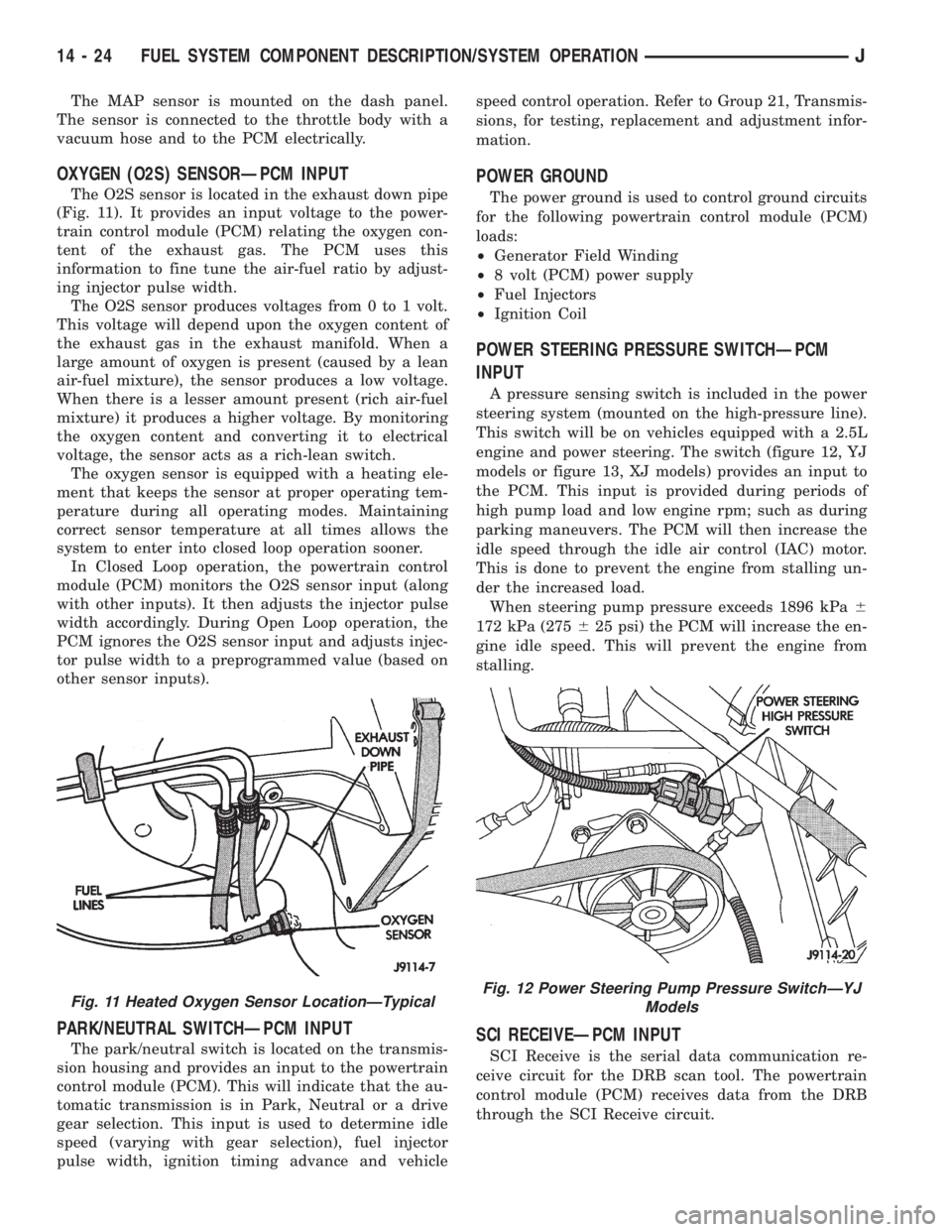
The O2S sensor is located in the exhaust down pipe
(Fig. 11). It provides an input voltage to the power-
train control module (PCM) relating the oxygen con-
tent of the exhaust gas. The PCM uses this
information to fine tune the air-fuel ratio by adjust-
ing injector pulse width.
The O2S sensor produces voltages from 0 to 1 volt.
This voltage will depend upon the oxygen content of
the exhaust gas in the exhaust manifold. When a
large amount of oxygen is present (caused by a lean
air-fuel mixture), the sensor produces a low voltage.
When there is a lesser amount present (rich air-fuel
mixture) it produces a higher voltage. By monitoring
the oxygen content and converting it to electrical
voltage, the sensor acts as a rich-lean switch.
The oxygen sensor is equipped with a heating ele-
ment that keeps the sensor at proper operating tem-
perature during all operating modes. Maintaining
correct sensor temperature at all times allows the
system to enter into closed loop operation sooner.
In Closed Loop operation, the powertrain control
module (PCM) monitors the O2S sensor input (along
with other inputs). It then adjusts the injector pulse
width accordingly. During Open Loop operation, the
PCM ignores the O2S sensor input and adjusts injec-
tor pulse width to a preprogrammed value (based on
other sensor inputs).
PARK/NEUTRAL SWITCHÐPCM INPUT
The park/neutral switch is located on the transmis-
sion housing and provides an input to the powertrain
control module (PCM). This will indicate that the au-
tomatic transmission is in Park, Neutral or a drive
gear selection. This input is used to determine idle
speed (varying with gear selection), fuel injector
pulse width, ignition timing advance and vehiclespeed control operation. Refer to Group 21, Transmis-
sions, for testing, replacement and adjustment infor-
mation.
POWER GROUND
The power ground is used to control ground circuits
for the following powertrain control module (PCM)
loads:
²Generator Field Winding
²8 volt (PCM) power supply
²Fuel Injectors
²Ignition Coil
POWER STEERING PRESSURE SWITCHÐPCM
INPUT
A pressure sensing switch is included in the power
steering system (mounted on the high-pressure line).
This switch will be on vehicles equipped with a 2.5L
engine and power steering. The switch (figure 12, YJ
models or figure 13, XJ models) provides an input to
the PCM. This input is provided during periods of
high pump load and low engine rpm; such as during
parking maneuvers. The PCM will then increase the
idle speed through the idle air control (IAC) motor.
This is done to prevent the engine from stalling un-
der the increased load.
When steering pump pressure exceeds 1896 kPa6
172 kPa (275625 psi) the PCM will increase the en-
gine idle speed. This will prevent the engine from
stalling.
SCI RECEIVEÐPCM INPUT
SCI Receive is the serial data communication re-
ceive circuit for the DRB scan tool. The powertrain
control module (PCM) receives data from the DRB
through the SCI Receive circuit.
Fig. 11 Heated Oxygen Sensor LocationÐTypicalFig. 12 Power Steering Pump Pressure SwitchÐYJ
Models
14 - 24 FUEL SYSTEM COMPONENT DESCRIPTION/SYSTEM OPERATIONJ
Page 1432 of 2158
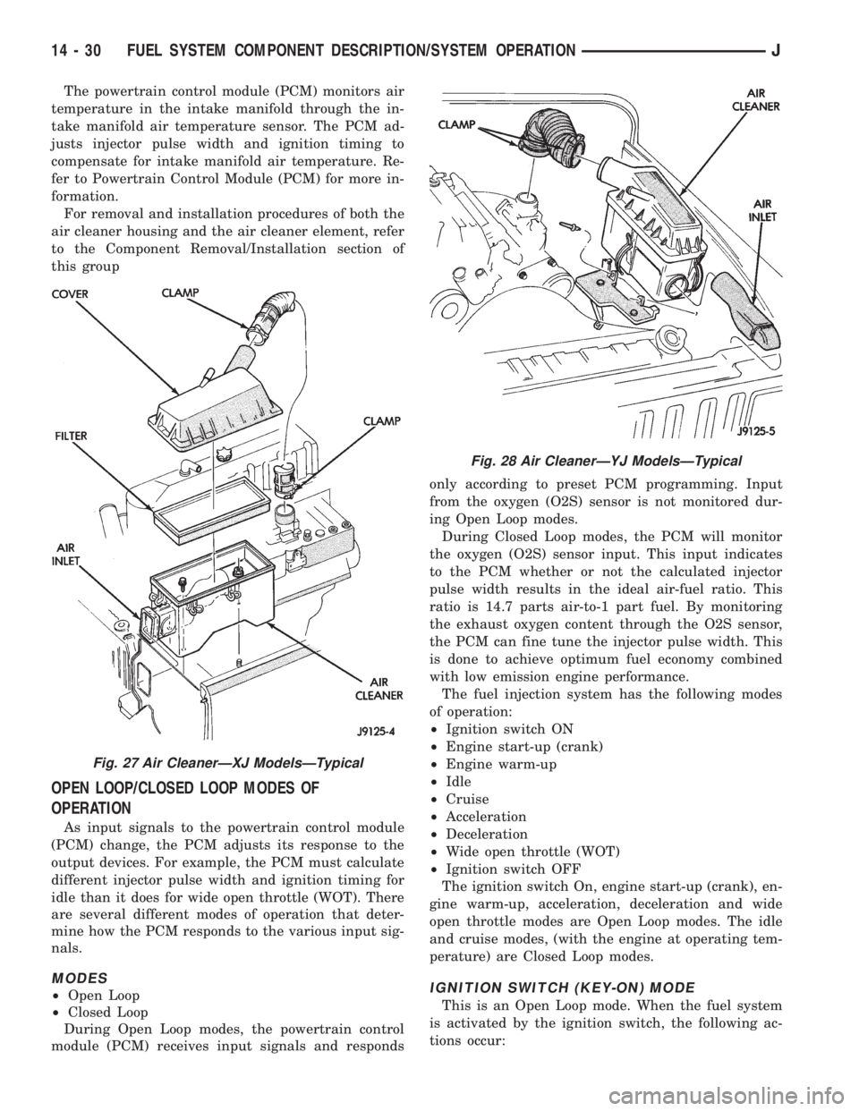
The powertrain control module (PCM) monitors air
temperature in the intake manifold through the in-
take manifold air temperature sensor. The PCM ad-
justs injector pulse width and ignition timing to
compensate for intake manifold air temperature. Re-
fer to Powertrain Control Module (PCM) for more in-
formation.
For removal and installation procedures of both the
air cleaner housing and the air cleaner element, refer
to the Component Removal/Installation section of
this group
OPEN LOOP/CLOSED LOOP MODES OF
OPERATION
As input signals to the powertrain control module
(PCM) change, the PCM adjusts its response to the
output devices. For example, the PCM must calculate
different injector pulse width and ignition timing for
idle than it does for wide open throttle (WOT). There
are several different modes of operation that deter-
mine how the PCM responds to the various input sig-
nals.
MODES
²Open Loop
²Closed Loop
During Open Loop modes, the powertrain control
module (PCM) receives input signals and respondsonly according to preset PCM programming. Input
from the oxygen (O2S) sensor is not monitored dur-
ing Open Loop modes.
During Closed Loop modes, the PCM will monitor
the oxygen (O2S) sensor input. This input indicates
to the PCM whether or not the calculated injector
pulse width results in the ideal air-fuel ratio. This
ratio is 14.7 parts air-to-1 part fuel. By monitoring
the exhaust oxygen content through the O2S sensor,
the PCM can fine tune the injector pulse width. This
is done to achieve optimum fuel economy combined
with low emission engine performance.
The fuel injection system has the following modes
of operation:
²Ignition switch ON
²Engine start-up (crank)
²Engine warm-up
²Idle
²Cruise
²Acceleration
²Deceleration
²Wide open throttle (WOT)
²Ignition switch OFF
The ignition switch On, engine start-up (crank), en-
gine warm-up, acceleration, deceleration and wide
open throttle modes are Open Loop modes. The idle
and cruise modes, (with the engine at operating tem-
perature) are Closed Loop modes.IGNITION SWITCH (KEY-ON) MODE
This is an Open Loop mode. When the fuel system
is activated by the ignition switch, the following ac-
tions occur:
Fig. 27 Air CleanerÐXJ ModelsÐTypical
Fig. 28 Air CleanerÐYJ ModelsÐTypical
14 - 30 FUEL SYSTEM COMPONENT DESCRIPTION/SYSTEM OPERATIONJ
Page 1441 of 2158
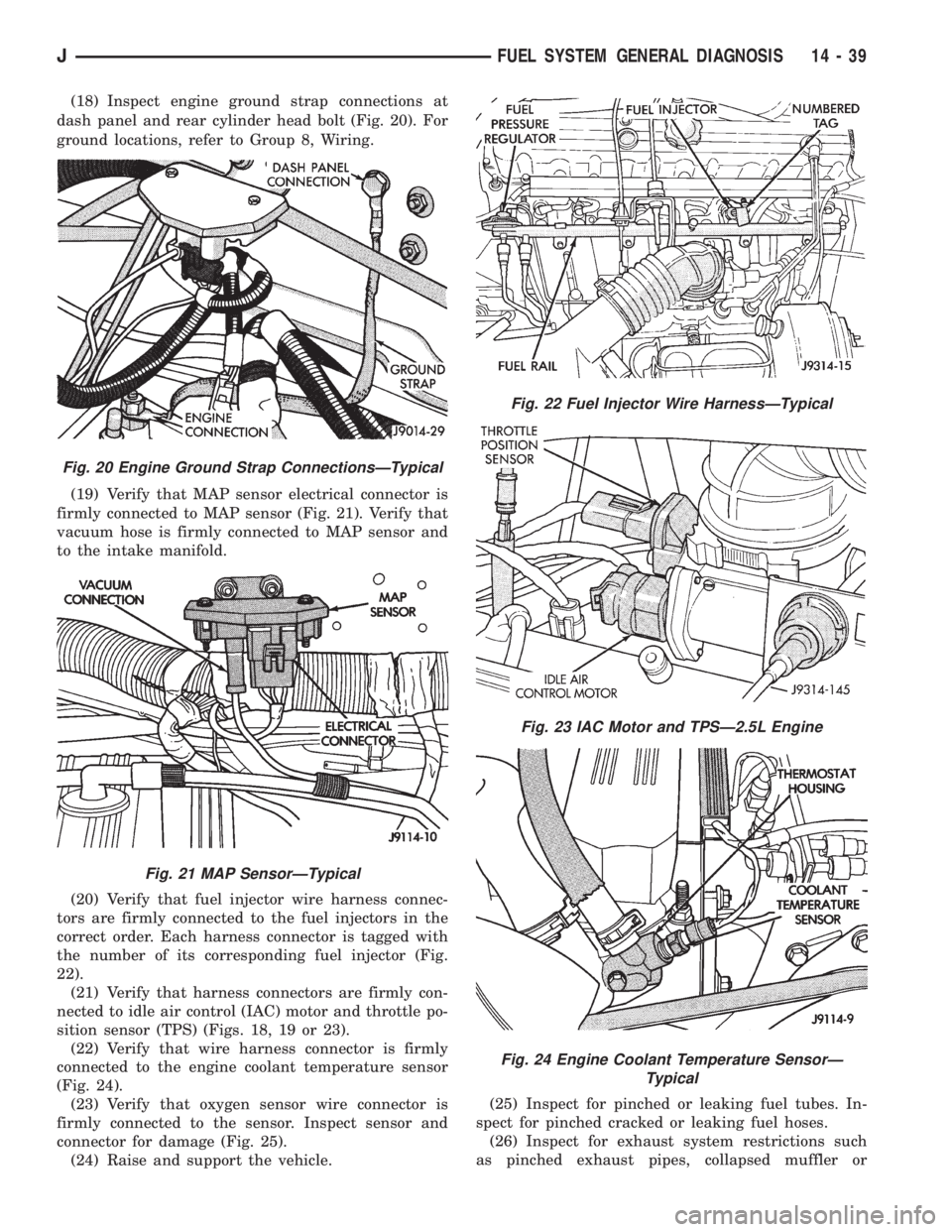
(18) Inspect engine ground strap connections at
dash panel and rear cylinder head bolt (Fig. 20). For
ground locations, refer to Group 8, Wiring.
(19) Verify that MAP sensor electrical connector is
firmly connected to MAP sensor (Fig. 21). Verify that
vacuum hose is firmly connected to MAP sensor and
to the intake manifold.
(20) Verify that fuel injector wire harness connec-
tors are firmly connected to the fuel injectors in the
correct order. Each harness connector is tagged with
the number of its corresponding fuel injector (Fig.
22).
(21) Verify that harness connectors are firmly con-
nected to idle air control (IAC) motor and throttle po-
sition sensor (TPS) (Figs. 18, 19 or 23).
(22) Verify that wire harness connector is firmly
connected to the engine coolant temperature sensor
(Fig. 24).
(23) Verify that oxygen sensor wire connector is
firmly connected to the sensor. Inspect sensor and
connector for damage (Fig. 25).
(24) Raise and support the vehicle.(25) Inspect for pinched or leaking fuel tubes. In-
spect for pinched cracked or leaking fuel hoses.
(26) Inspect for exhaust system restrictions such
as pinched exhaust pipes, collapsed muffler or
Fig. 20 Engine Ground Strap ConnectionsÐTypical
Fig. 21 MAP SensorÐTypical
Fig. 22 Fuel Injector Wire HarnessÐTypical
Fig. 23 IAC Motor and TPSÐ2.5L Engine
Fig. 24 Engine Coolant Temperature SensorÐ
Typical
JFUEL SYSTEM GENERAL DIAGNOSIS 14 - 39
Page 1451 of 2158
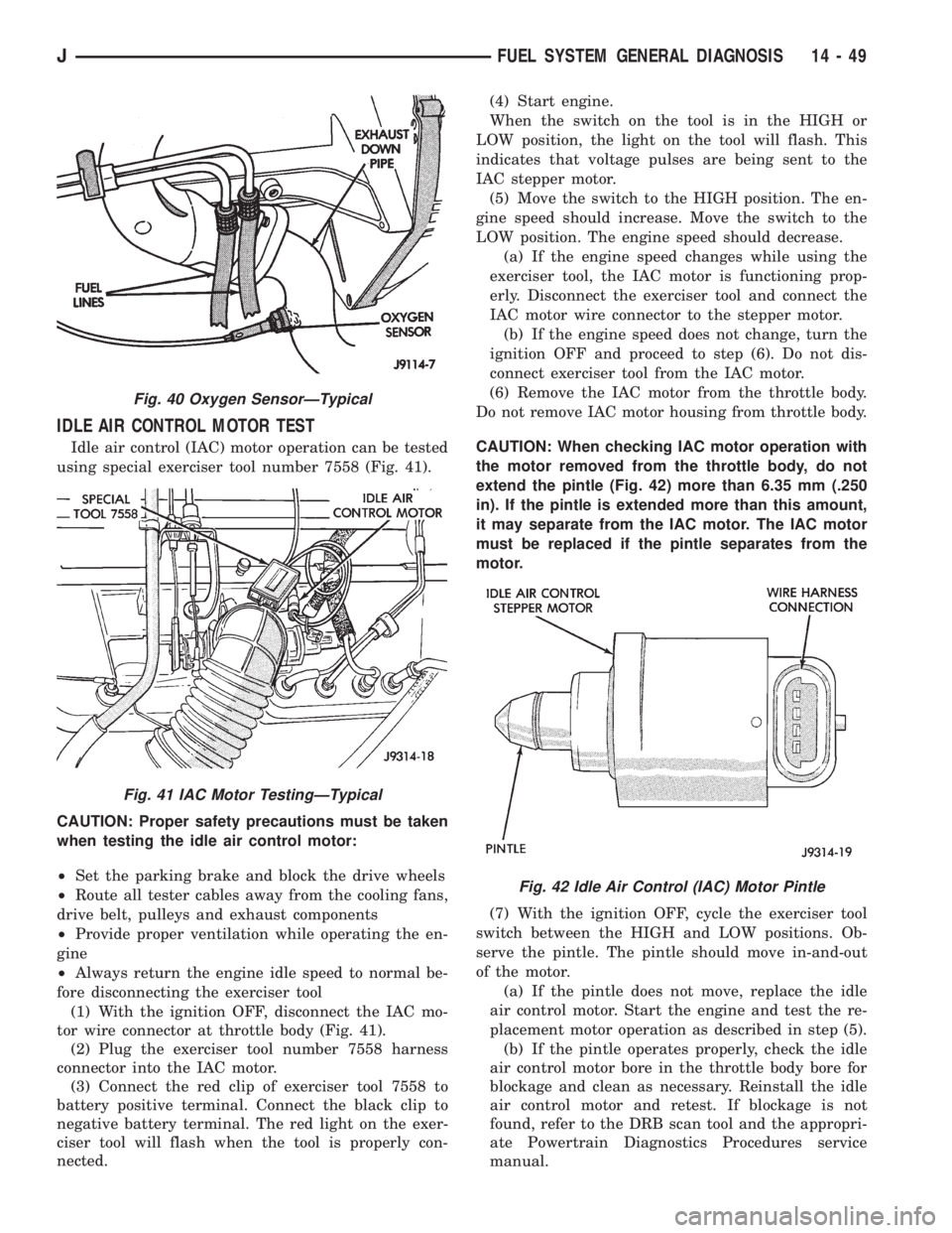
IDLE AIR CONTROL MOTOR TEST
Idle air control (IAC) motor operation can be tested
using special exerciser tool number 7558 (Fig. 41).
CAUTION: Proper safety precautions must be taken
when testing the idle air control motor:
²Set the parking brake and block the drive wheels
²Route all tester cables away from the cooling fans,
drive belt, pulleys and exhaust components
²Provide proper ventilation while operating the en-
gine
²Always return the engine idle speed to normal be-
fore disconnecting the exerciser tool
(1) With the ignition OFF, disconnect the IAC mo-
tor wire connector at throttle body (Fig. 41).
(2) Plug the exerciser tool number 7558 harness
connector into the IAC motor.
(3) Connect the red clip of exerciser tool 7558 to
battery positive terminal. Connect the black clip to
negative battery terminal. The red light on the exer-
ciser tool will flash when the tool is properly con-
nected.(4) Start engine.
When the switch on the tool is in the HIGH or
LOW position, the light on the tool will flash. This
indicates that voltage pulses are being sent to the
IAC stepper motor.
(5) Move the switch to the HIGH position. The en-
gine speed should increase. Move the switch to the
LOW position. The engine speed should decrease.
(a) If the engine speed changes while using the
exerciser tool, the IAC motor is functioning prop-
erly. Disconnect the exerciser tool and connect the
IAC motor wire connector to the stepper motor.
(b) If the engine speed does not change, turn the
ignition OFF and proceed to step (6). Do not dis-
connect exerciser tool from the IAC motor.
(6) Remove the IAC motor from the throttle body.
Do not remove IAC motor housing from throttle body.
CAUTION: When checking IAC motor operation with
the motor removed from the throttle body, do not
extend the pintle (Fig. 42) more than 6.35 mm (.250
in). If the pintle is extended more than this amount,
it may separate from the IAC motor. The IAC motor
must be replaced if the pintle separates from the
motor.
(7) With the ignition OFF, cycle the exerciser tool
switch between the HIGH and LOW positions. Ob-
serve the pintle. The pintle should move in-and-out
of the motor.
(a) If the pintle does not move, replace the idle
air control motor. Start the engine and test the re-
placement motor operation as described in step (5).
(b) If the pintle operates properly, check the idle
air control motor bore in the throttle body bore for
blockage and clean as necessary. Reinstall the idle
air control motor and retest. If blockage is not
found, refer to the DRB scan tool and the appropri-
ate Powertrain Diagnostics Procedures service
manual.
Fig. 40 Oxygen SensorÐTypical
Fig. 41 IAC Motor TestingÐTypical
Fig. 42 Idle Air Control (IAC) Motor Pintle
JFUEL SYSTEM GENERAL DIAGNOSIS 14 - 49
Page 1455 of 2158
line. However, these could result in a rich or lean
condition causing an oxygen sensor DTC to be stored
in the PCM.
Secondary Ignition Circuit:The PCM cannot
detect an inoperative ignition coil, fouled or worn
spark plugs, ignition cross firing, or open circuited
spark plug cables.
Engine Timing:The PCM cannot detect an incor-
rectly indexed timing chain, camshaft sprocket or
crankshaft sprocket. The PCM also cannot detect an
incorrectly indexed distributor. However, these could
result in a rich or lean condition causing an oxygen
sensor DTC to be stored in the PCM.
Cylinder Compression:The PCM cannot detect
uneven, low, or high engine cylinder compression.
Exhaust System:The PCM cannot detect a
plugged, restricted or leaking exhaust system.
Fuel Injector Malfunctions:The PCM cannot de-
termine if the fuel injector is clogged, or the wrong
injector is installed. However, these could result in a
rich or lean condition causing an oxygen sensor DTC
to be stored in the PCM.
Excessive Oil Consumption:Although the PCM
monitors exhaust stream oxygen content through ox-
ygen sensor (closed loop), it cannot determine exces-
sive oil consumption.
Throttle Body Air Flow:The PCM cannot detect
a clogged or restricted air cleaner inlet or air cleaner
element.
Evaporative System:The PCM will not detect a
restricted, plugged or loaded EVAP canister.
Vacuum Assist:Leaks or restrictions in the vac-
uum circuits of vacuum assisted engine control sys-
tem devices are not monitored by the PCM. However,
a vacuum leak at the MAP sensor will be monitored
and a diagnostic trouble code (DTC) will be gener-
ated by the PCM.
Powertrain Control Module (PCM) System
Ground:The PCM cannot determine a poor system
ground. However, a DTC may be generated as a re-
sult of this condition.
Powertrain Control Module (PCM) Connector
Engagement:The PCM cannot determine spread or
damaged connector pins. However, a DTC may be
generated as a result of this condition.
HIGH AND LOW LIMITS
The powertrain control module (PCM) compares in-
put signal voltages from each input device. It will es-
tablish high and low limits that are programmed into
it for that device. If the input voltage is not within
specifications and other Diagnostic Trouble Code
(DTC) criteria are met, a DTC will be stored in mem-
ory. Other DTC criteria might include engine rpm
limits or input voltages from other sensors or
switches. The other inputs might have to be sensed
by the PCM when it senses a high or low input volt-
age from the control system device in question.
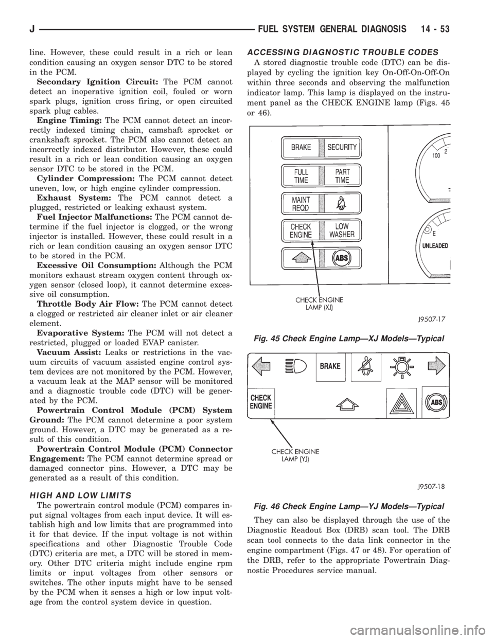
ACCESSING DIAGNOSTIC TROUBLE CODES
A stored diagnostic trouble code (DTC) can be dis-
played by cycling the ignition key On-Off-On-Off-On
within three seconds and observing the malfunction
indicator lamp. This lamp is displayed on the instru-
ment panel as the CHECK ENGINE lamp (Figs. 45
or 46).
They can also be displayed through the use of the
Diagnostic Readout Box (DRB) scan tool. The DRB
scan tool connects to the data link connector in the
engine compartment (Figs. 47 or 48). For operation of
the DRB, refer to the appropriate Powertrain Diag-
nostic Procedures service manual.
Fig. 45 Check Engine LampÐXJ ModelsÐTypical
Fig. 46 Check Engine LampÐYJ ModelsÐTypical
JFUEL SYSTEM GENERAL DIAGNOSIS 14 - 53