1995 JEEP XJ ECU
[x] Cancel search: ECUPage 29 of 2158
CAUTION: Do not crank starter motor on disabled
vehicle for more than 15 seconds, starter will over-
heat and could fail.
(6) Allow battery in disabled vehicle to charge to at
least 12.4 volts (75%charge) before attempting to
start engine. If engine does not start within 15 sec-
onds, stop cranking engine and allow starter to cool
(15 min.), before cranking again.
DISCONNECT CABLE CLAMPS AS FOLLOWS:
²Disconnect BLACK cable clamp from engine
ground on disabled vehicle.
²When using a Booster vehicle, disconnect BLACK
cable clamp from battery negative terminal. Discon-
nect RED cable clamp from battery positive terminal.
²Disconnect RED cable clamp from battery positive
terminal on disabled vehicle.
PORTABLE STARTING UNIT
There are many types of portable starting units
available for starting engines. Follow the manufac-
turer's instructions and observe the listed precau-
tions when involved in any engine starting
procedure.
HOISTING RECOMMENDATIONS
Refer to the Owner's Manual for emergency vehicle
lifting procedures.
FLOOR JACK
When properly positioned, a floor jack can be used
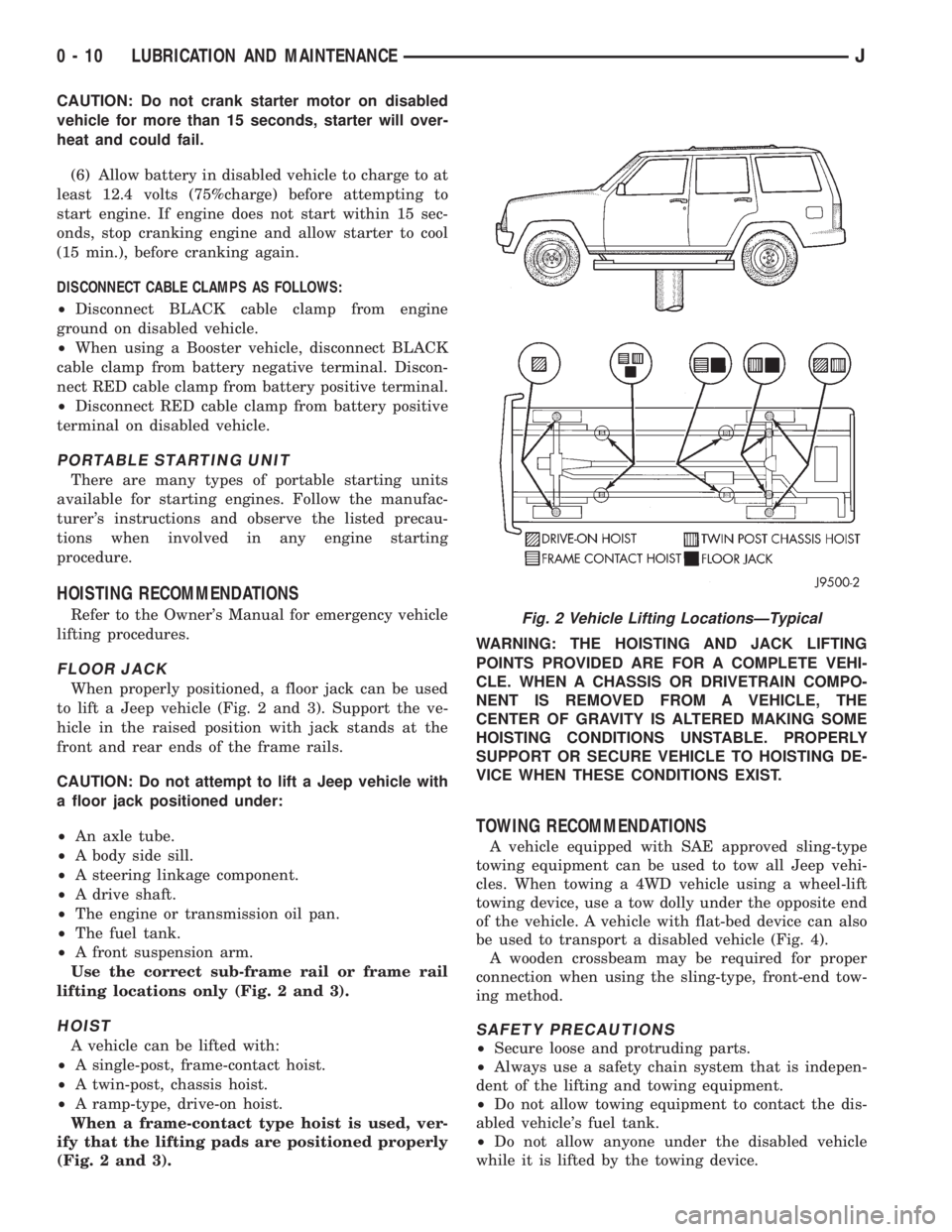
to lift a Jeep vehicle (Fig. 2 and 3). Support the ve-
hicle in the raised position with jack stands at the
front and rear ends of the frame rails.
CAUTION: Do not attempt to lift a Jeep vehicle with
a floor jack positioned under:
²An axle tube.
²A body side sill.
²A steering linkage component.
²A drive shaft.
²The engine or transmission oil pan.
²The fuel tank.
²A front suspension arm.
Use the correct sub-frame rail or frame rail
lifting locations only (Fig. 2 and 3).
HOIST
A vehicle can be lifted with:
²A single-post, frame-contact hoist.
²A twin-post, chassis hoist.
²A ramp-type, drive-on hoist.
When a frame-contact type hoist is used, ver-
ify that the lifting pads are positioned properly
(Fig. 2 and 3).WARNING: THE HOISTING AND JACK LIFTING
POINTS PROVIDED ARE FOR A COMPLETE VEHI-
CLE. WHEN A CHASSIS OR DRIVETRAIN COMPO-
NENT IS REMOVED FROM A VEHICLE, THE
CENTER OF GRAVITY IS ALTERED MAKING SOME
HOISTING CONDITIONS UNSTABLE. PROPERLY
SUPPORT OR SECURE VEHICLE TO HOISTING DE-
VICE WHEN THESE CONDITIONS EXIST.
TOWING RECOMMENDATIONS
A vehicle equipped with SAE approved sling-type
towing equipment can be used to tow all Jeep vehi-
cles. When towing a 4WD vehicle using a wheel-lift
towing device, use a tow dolly under the opposite end
of the vehicle. A vehicle with flat-bed device can also
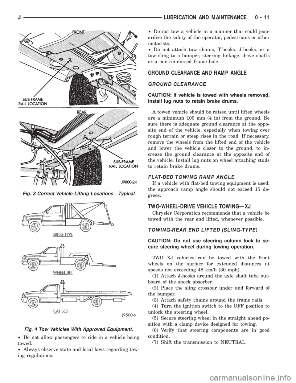
be used to transport a disabled vehicle (Fig. 4).
A wooden crossbeam may be required for proper
connection when using the sling-type, front-end tow-
ing method.
SAFETY PRECAUTIONS
²Secure loose and protruding parts.
²Always use a safety chain system that is indepen-
dent of the lifting and towing equipment.
²Do not allow towing equipment to contact the dis-
abled vehicle's fuel tank.
²Do not allow anyone under the disabled vehicle
while it is lifted by the towing device.
Fig. 2 Vehicle Lifting LocationsÐTypical
0 - 10 LUBRICATION AND MAINTENANCEJ
Page 30 of 2158
²Do not allow passengers to ride in a vehicle being
towed.
²Always observe state and local laws regarding tow-
ing regulations.²Do not tow a vehicle in a manner that could jeop-
ardize the safety of the operator, pedestrians or other
motorists.
²Do not attach tow chains, T-hooks, J-hooks, or a
tow sling to a bumper, steering linkage, drive shafts
or a non-reinforced frame hole.
GROUND CLEARANCE AND RAMP ANGLE
GROUND CLEARANCE
CAUTION: If vehicle is towed with wheels removed,
install lug nuts to retain brake drums.
A towed vehicle should be raised until lifted wheels
are a minimum 100 mm (4 in) from the ground. Be
sure there is adequate ground clearance at the oppo-
site end of the vehicle, especially when towing over
rough terrain or steep rises in the road. If necessary,
remove the wheels from the lifted end of the vehicle
and lower the vehicle closer to the ground, to in-
crease the ground clearance at the opposite end of
the vehicle. Install lug nuts on wheel attaching studs
to retain brake drums.
FLAT-BED TOWING RAMP ANGLE
If a vehicle with flat-bed towing equipment is used,
the approach ramp angle should not exceed 15 de-
grees.
TWO-WHEEL-DRIVE VEHICLE TOWINGÐXJ
Chrysler Corporation recommends that a vehicle be
towed with the rear end lifted, whenever possible.
TOWING-REAR END LIFTED (SLING-TYPE)
CAUTION: Do not use steering column lock to se-
cure steering wheel during towing operation.
2WD XJ vehicles can be towed with the front
wheels on the surface for extended distances at
speeds not exceeding 48 km/h (30 mph).
(1) Attach J-hooks around the axle shaft tube out-
board of the shock absorber.
(2) Place the sling crossbar under and forward of
the bumper.
(3) Attach safety chains around the frame rails.
(4) Turn the ignition switch to the OFF position to
unlock the steering wheel.
(5) Secure steering wheel in the straight ahead po-
sition with a clamp device designed for towing.
(6) Verify that steering components are in good
condition.
(7) Shift the transmission to NEUTRAL.
Fig. 3 Correct Vehicle Lifting LocationsÐTypical
Fig. 4 Tow Vehicles With Approved Equipment.
JLUBRICATION AND MAINTENANCE 0 - 11
Page 31 of 2158
TOWING-FRONT END LIFTED (SLING-TYPE)
CAUTION: Many vehicles are equipped with air
dams, spoilers, and/or ground effect panels. To
avoid component damage, a wheel-lift towing vehi-
cle or a flat-bed hauling vehicle is recommended.
If a 2WD XJ vehicle cannot be towed with the rear
wheels lifted, it can be towed with the front wheels
lifted.
(1) Attach a J-hook to the disabled vehicle at the
left side of the axle.
(2) Position the sling crossbar close to the J-hook
and below the front bumper.
(3) Secure a chain to the right side of vehicle by
placing it over the axle shaft tube and attaching it to
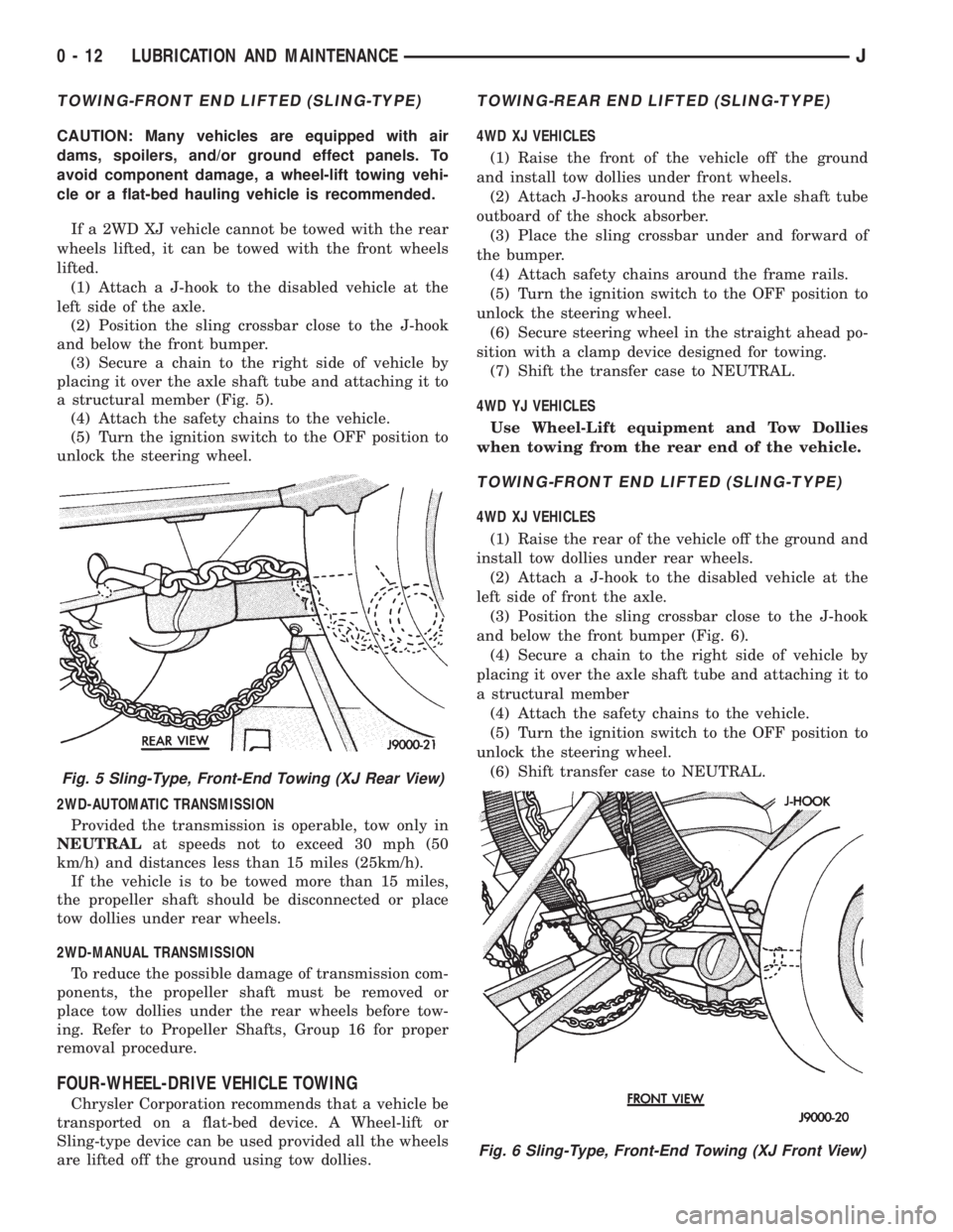
a structural member (Fig. 5).
(4) Attach the safety chains to the vehicle.
(5) Turn the ignition switch to the OFF position to
unlock the steering wheel.
2WD-AUTOMATIC TRANSMISSION
Provided the transmission is operable, tow only in
NEUTRALat speeds not to exceed 30 mph (50
km/h) and distances less than 15 miles (25km/h).
If the vehicle is to be towed more than 15 miles,
the propeller shaft should be disconnected or place
tow dollies under rear wheels.
2WD-MANUAL TRANSMISSION
To reduce the possible damage of transmission com-
ponents, the propeller shaft must be removed or
place tow dollies under the rear wheels before tow-
ing. Refer to Propeller Shafts, Group 16 for proper
removal procedure.
FOUR-WHEEL-DRIVE VEHICLE TOWING
Chrysler Corporation recommends that a vehicle be
transported on a flat-bed device. A Wheel-lift or
Sling-type device can be used provided all the wheels
are lifted off the ground using tow dollies.
TOWING-REAR END LIFTED (SLING-TYPE)
4WD XJ VEHICLES
(1) Raise the front of the vehicle off the ground
and install tow dollies under front wheels.
(2) Attach J-hooks around the rear axle shaft tube
outboard of the shock absorber.
(3) Place the sling crossbar under and forward of
the bumper.
(4) Attach safety chains around the frame rails.
(5) Turn the ignition switch to the OFF position to
unlock the steering wheel.
(6) Secure steering wheel in the straight ahead po-
sition with a clamp device designed for towing.
(7) Shift the transfer case to NEUTRAL.
4WD YJ VEHICLES
Use Wheel-Lift equipment and Tow Dollies
when towing from the rear end of the vehicle.
TOWING-FRONT END LIFTED (SLING-TYPE)
4WD XJ VEHICLES
(1) Raise the rear of the vehicle off the ground and
install tow dollies under rear wheels.
(2) Attach a J-hook to the disabled vehicle at the
left side of front the axle.
(3) Position the sling crossbar close to the J-hook
and below the front bumper (Fig. 6).
(4) Secure a chain to the right side of vehicle by
placing it over the axle shaft tube and attaching it to
a structural member
(4) Attach the safety chains to the vehicle.
(5) Turn the ignition switch to the OFF position to
unlock the steering wheel.
(6) Shift transfer case to NEUTRAL.
Fig. 5 Sling-Type, Front-End Towing (XJ Rear View)
Fig. 6 Sling-Type, Front-End Towing (XJ Front View)
0 - 12 LUBRICATION AND MAINTENANCEJ
Page 45 of 2158
(11) Remove the support and lower the vehicle.
DRIVE SHAFTS
Lubricate at the intervals described in the Mainte-
nance Schedule section of this Group. Refer to Group
16, Propeller Shafts for proper service procedures.
CAUTION: It is very important that drive shafts be
lubricated at periodic intervals and that the speci-
fied type of lubricant be used. Failure to properly
lubricate could result in premature wear of drive
shaft components.
LUBRICANT SPECIFICATION
Use Mopar, Multi-purpose Grease or any lubricate
that is identified as NLGI GC-LB lubricant.
RUBBER AND PLASTIC HOSES/TUBING
The condition of underbody rubber hose and plastic
tubing should be inspected whenever underbody ser-
vice is performed.
Rubber hoses and plastic tubing should be re-
placed immediately if there is any evidence of
failure.
HOSE/TUBING INSPECTION
(1) Inspect all hose and tubing fittings for loose-
ness and corrosion. Inspect the rubber hoses for brit-
tleness and cracks. Thoroughly inspect the hose ends
(those that are slipped over nipple connectors) for
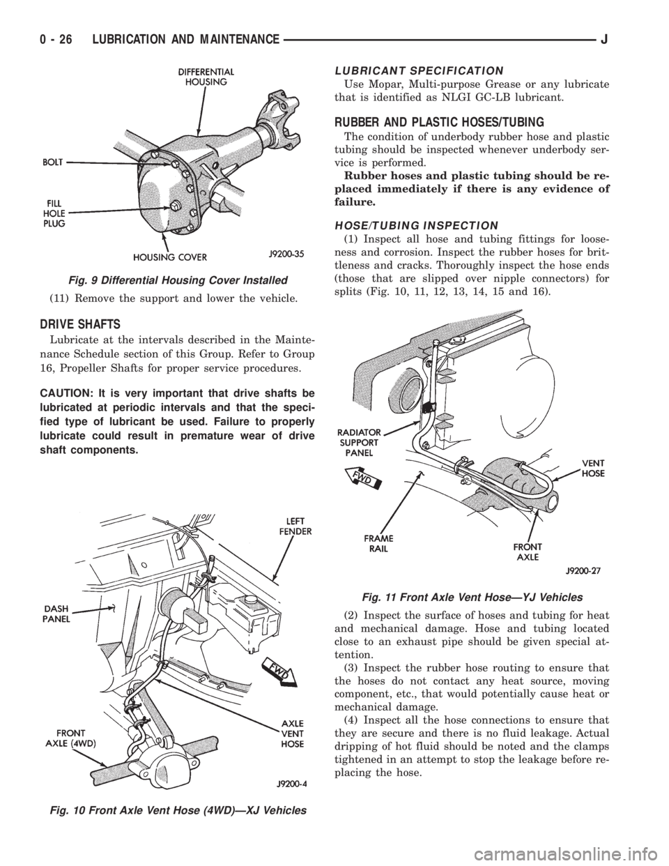
splits (Fig. 10, 11, 12, 13, 14, 15 and 16).
(2) Inspect the surface of hoses and tubing for heat
and mechanical damage. Hose and tubing located
close to an exhaust pipe should be given special at-
tention.
(3) Inspect the rubber hose routing to ensure that
the hoses do not contact any heat source, moving
component, etc., that would potentially cause heat or
mechanical damage.
(4) Inspect all the hose connections to ensure that
they are secure and there is no fluid leakage. Actual
dripping of hot fluid should be noted and the clamps
tightened in an attempt to stop the leakage before re-
placing the hose.
Fig. 10 Front Axle Vent Hose (4WD)ÐXJ Vehicles
Fig. 9 Differential Housing Cover Installed
Fig. 11 Front Axle Vent HoseÐYJ Vehicles
0 - 26 LUBRICATION AND MAINTENANCEJ
Page 48 of 2158
hose unless the caliper must also be removed
for maintenance.Support the caliper with a
hanger to prevent brake fluid hose damage.
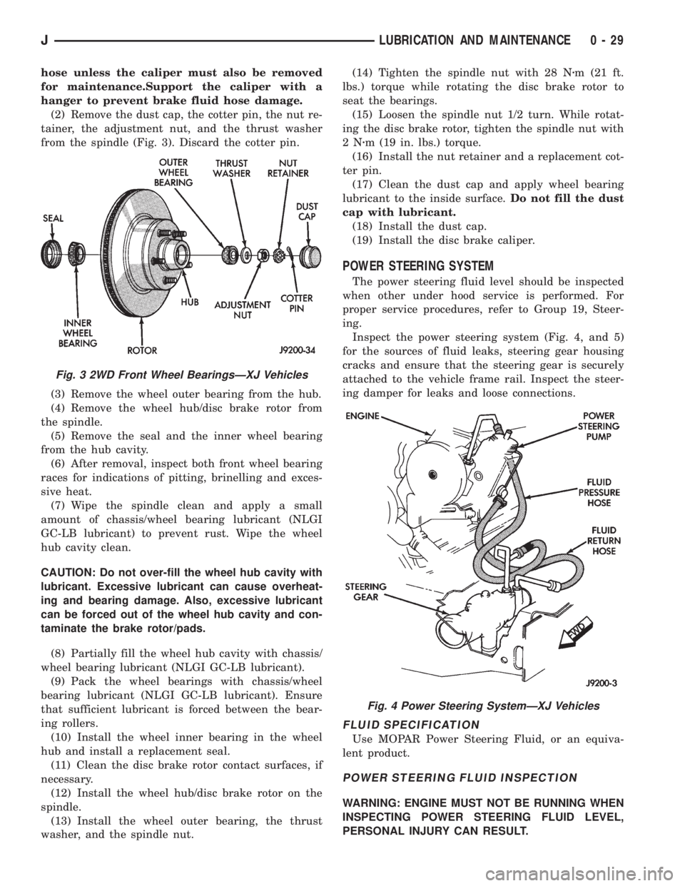
(2) Remove the dust cap, the cotter pin, the nut re-
tainer, the adjustment nut, and the thrust washer
from the spindle (Fig. 3). Discard the cotter pin.
(3) Remove the wheel outer bearing from the hub.
(4) Remove the wheel hub/disc brake rotor from
the spindle.
(5) Remove the seal and the inner wheel bearing
from the hub cavity.
(6) After removal, inspect both front wheel bearing
races for indications of pitting, brinelling and exces-
sive heat.
(7) Wipe the spindle clean and apply a small
amount of chassis/wheel bearing lubricant (NLGI
GC-LB lubricant) to prevent rust. Wipe the wheel
hub cavity clean.
CAUTION: Do not over-fill the wheel hub cavity with
lubricant. Excessive lubricant can cause overheat-
ing and bearing damage. Also, excessive lubricant
can be forced out of the wheel hub cavity and con-
taminate the brake rotor/pads.
(8) Partially fill the wheel hub cavity with chassis/
wheel bearing lubricant (NLGI GC-LB lubricant).
(9) Pack the wheel bearings with chassis/wheel
bearing lubricant (NLGI GC-LB lubricant). Ensure
that sufficient lubricant is forced between the bear-
ing rollers.
(10) Install the wheel inner bearing in the wheel
hub and install a replacement seal.
(11) Clean the disc brake rotor contact surfaces, if
necessary.
(12) Install the wheel hub/disc brake rotor on the
spindle.
(13) Install the wheel outer bearing, the thrust
washer, and the spindle nut.(14) Tighten the spindle nut with 28 Nzm (21 ft.
lbs.) torque while rotating the disc brake rotor to
seat the bearings.
(15) Loosen the spindle nut 1/2 turn. While rotat-
ing the disc brake rotor, tighten the spindle nut with
2Nzm (19 in. lbs.) torque.
(16) Install the nut retainer and a replacement cot-
ter pin.
(17) Clean the dust cap and apply wheel bearing
lubricant to the inside surface.Do not fill the dust
cap with lubricant.
(18) Install the dust cap.
(19) Install the disc brake caliper.
POWER STEERING SYSTEM
The power steering fluid level should be inspected
when other under hood service is performed. For
proper service procedures, refer to Group 19, Steer-
ing.
Inspect the power steering system (Fig. 4, and 5)
for the sources of fluid leaks, steering gear housing
cracks and ensure that the steering gear is securely
attached to the vehicle frame rail. Inspect the steer-
ing damper for leaks and loose connections.
FLUID SPECIFICATION
Use MOPAR Power Steering Fluid, or an equiva-
lent product.
POWER STEERING FLUID INSPECTION
WARNING: ENGINE MUST NOT BE RUNNING WHEN
INSPECTING POWER STEERING FLUID LEVEL,
PERSONAL INJURY CAN RESULT.
Fig. 3 2WD Front Wheel BearingsÐXJ Vehicles
Fig. 4 Power Steering SystemÐXJ Vehicles
JLUBRICATION AND MAINTENANCE 0 - 29
Page 61 of 2158
wheels. Secure the steering wheel with the front
wheels in the straight-ahead position. Turn off the
engine.
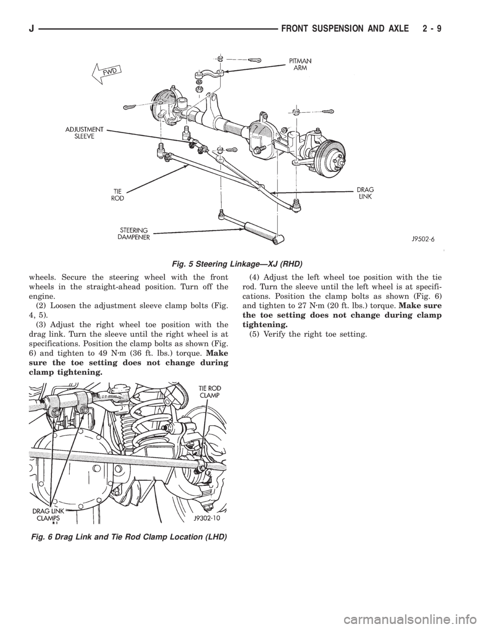
(2) Loosen the adjustment sleeve clamp bolts (Fig.
4, 5).
(3) Adjust the right wheel toe position with the
drag link. Turn the sleeve until the right wheel is at
specifications. Position the clamp bolts as shown (Fig.
6) and tighten to 49 Nzm (36 ft. lbs.) torque.Make
sure the toe setting does not change during
clamp tightening.(4) Adjust the left wheel toe position with the tie
rod. Turn the sleeve until the left wheel is at specifi-
cations. Position the clamp bolts as shown (Fig. 6)
and tighten to 27 Nzm (20 ft. lbs.) torque.Make sure
the toe setting does not change during clamp
tightening.
(5) Verify the right toe setting.
Fig. 5 Steering LinkageÐXJ (RHD)
Fig. 6 Drag Link and Tie Rod Clamp Location (LHD)
JFRONT SUSPENSION AND AXLE 2 - 9
Page 62 of 2158
TOE POSITIONÐYJ VEHICLES
The wheel toe position should be the final front
wheel alignment adjustment. In all instances follow
the equipment manufacturer's recommended proce-
dure.
(1) Start the engine if equipped with power steer-
ing. Turn wheels both ways before straightening the
wheels. Secure the steering wheel with the front
wheels in the straight-ahead position. Turn off the
engine.
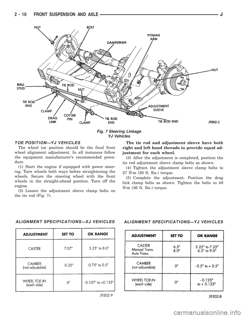
(2) Loosen the adjustment sleeve clamp bolts on
the tie rod (Fig. 7).The tie rod and adjustment sleeve have both
right and left hand threads to provide equal ad-
justment for each wheel.
(3) After the adjustment is completed, position the
tie rod adjustment sleeve clamp bolts as shown.
(4) Tighten the adjustment sleeve clamp bolts to
27 Nzm (20 ft. lbs.) torque.
(5) Complete the adjustment. Position the drag
link clamp bolts as shown. Tighten the bolts to 49
Nzm (36 ft. lbs.) torque.
Fig. 7 Steering Linkage
YJ Vehicles
ALIGNMENT SPECIFICATIONSÐXJ VEHICLESALIGNMENT SPECIFICATIONSÐYJ VEHICLES
2 - 10 FRONT SUSPENSION AND AXLEJ
Page 134 of 2158
BEARING AND SEAL INSTALLATION
Do not install the original axle shaft seal. Al-
ways install a new seal.
(1) Wipe the bore in the axle shaft tube clean.
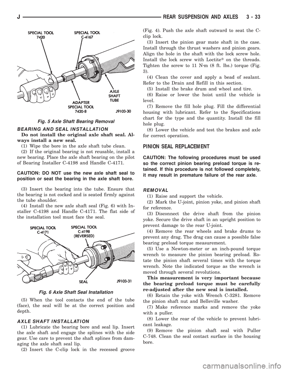
(2) If the original bearing is not reusable, install a
new bearing. Place the axle shaft bearing on the pilot
of Bearing Installer C-4198 and Handle C-4171.
CAUTION: DO NOT use the new axle shaft seal to
position or seat the bearing in the axle shaft bore.
(3) Insert the bearing into the tube. Ensure that
the bearing is not cocked and is seated firmly against
the tube shoulder.
(4) Install the new axle shaft seal (Fig. 6) with In-
staller C-4198 and Handle C-4171. The flat side of
the installation tool must face the seal.
(5) When the tool contacts the end of the tube
(face), the seal will be at the correct position and
depth.
AXLE SHAFT INSTALLATION
(1) Lubricate the bearing bore and seal lip. Insert
the axle shaft and engage the splines with the side
gear. Use care to prevent the shaft splines from dam-
aging the axle shaft seal lip.
(2) Insert the C-clip lock in the recessed groove(Fig. 4). Push the axle shaft outward to seat the C-
clip lock.
(3) Insert the pinion gear mate shaft in the case.
Install through the thrust washers and pinion gears.
Align the hole in the shaft with the lock screw hole.
Install the lock screw with Loctiteton the threads.
Tighten the screw to 11 Nzm (8 ft. lbs.) torque (Fig.
3).
(4) Clean the cover and apply a bead of sealant.
Refer to the Drain and Refill in this section.
(5) Install the brake drum and wheel and tire.
(6) Raise or lower the hoist until the vehicle is
level.
(7) Remove the fill hole plug. Fill the differential
housing with lubricant. Refer to the Specifications
chart for the type and the quantity. Install the fill
hole plug.
(8) Lower the vehicle and test the brakes and axle
for correct operation.
PINION SEAL REPLACEMENT
CAUTION: The following procedures must be used
so the correct pinion bearing preload torque is re-
tained. If this procedure is not followed completely,
it may result in premature failure of the rear axle.
REMOVAL
(1) Raise and support the vehicle.
(2) Mark the U-joint, pinion yoke, and pinion shaft
for reference.
(3) Disconnect the drive shaft from the pinion
yoke. Secure the drive shaft in an upright position to
prevent damage to the rear U-joint.
(4) Remove the rear wheels and brake drums to
prevent any drag. The drag can cause a possible false
bearing preload torque measurement.
(5) Use a Newton-meter or an inch-pound torque
wrench to measure the pinion bearing preload. Ro-
tate the pinion shaft several times with the torque
wrench. Note the indicated torque as the wrench is
moved through several revolutions.
This measurement is very important because
the bearing preload torque must be carefully
re-adjusted after the new seal is installed.
(6) Retain the yoke with Wrench C-3281. Remove
the pinion shaft nut and Belleville washer.
(7) Make reference marks and remove the yoke
with a puller.
(8) Lower the rear of the vehicle to prevent lubri-
cant leakage.
(9) Remove the pinion shaft seal with Puller
C-748. Clean the seal contact surface in the housing
bore.
Fig. 5 Axle Shaft Bearing Removal
Fig. 6 Axle Shaft Seal Installation
JREAR SUSPENSION AND AXLES 3 - 33