1995 JEEP XJ Exhaust
[x] Cancel search: ExhaustPage 1345 of 2158
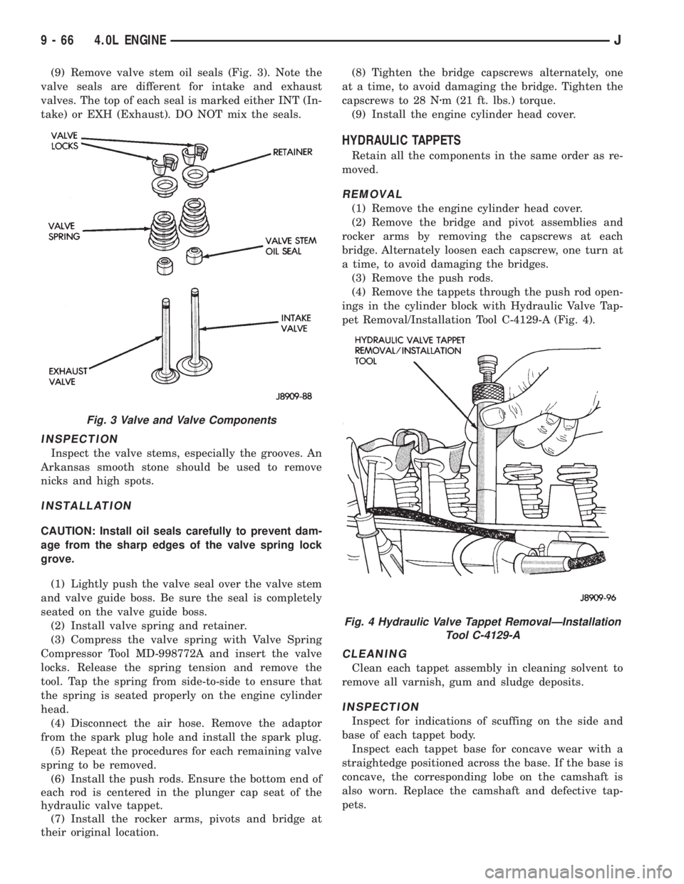
(9) Remove valve stem oil seals (Fig. 3). Note the
valve seals are different for intake and exhaust
valves. The top of each seal is marked either INT (In-
take) or EXH (Exhaust). DO NOT mix the seals.
INSPECTION
Inspect the valve stems, especially the grooves. An
Arkansas smooth stone should be used to remove
nicks and high spots.
INSTALLATION
CAUTION: Install oil seals carefully to prevent dam-
age from the sharp edges of the valve spring lock
grove.
(1) Lightly push the valve seal over the valve stem
and valve guide boss. Be sure the seal is completely
seated on the valve guide boss.
(2) Install valve spring and retainer.
(3) Compress the valve spring with Valve Spring
Compressor Tool MD-998772A and insert the valve
locks. Release the spring tension and remove the
tool. Tap the spring from side-to-side to ensure that
the spring is seated properly on the engine cylinder
head.
(4) Disconnect the air hose. Remove the adaptor
from the spark plug hole and install the spark plug.
(5) Repeat the procedures for each remaining valve
spring to be removed.
(6) Install the push rods. Ensure the bottom end of
each rod is centered in the plunger cap seat of the
hydraulic valve tappet.
(7) Install the rocker arms, pivots and bridge at
their original location.(8) Tighten the bridge capscrews alternately, one
at a time, to avoid damaging the bridge. Tighten the
capscrews to 28 Nzm (21 ft. lbs.) torque.
(9) Install the engine cylinder head cover.
HYDRAULIC TAPPETS
Retain all the components in the same order as re-
moved.
REMOVAL
(1) Remove the engine cylinder head cover.
(2) Remove the bridge and pivot assemblies and
rocker arms by removing the capscrews at each
bridge. Alternately loosen each capscrew, one turn at
a time, to avoid damaging the bridges.
(3) Remove the push rods.
(4) Remove the tappets through the push rod open-
ings in the cylinder block with Hydraulic Valve Tap-
pet Removal/Installation Tool C-4129-A (Fig. 4).
CLEANING
Clean each tappet assembly in cleaning solvent to
remove all varnish, gum and sludge deposits.
INSPECTION
Inspect for indications of scuffing on the side and
base of each tappet body.
Inspect each tappet base for concave wear with a
straightedge positioned across the base. If the base is
concave, the corresponding lobe on the camshaft is
also worn. Replace the camshaft and defective tap-
pets.
Fig. 3 Valve and Valve Components
Fig. 4 Hydraulic Valve Tappet RemovalÐInstallation
Tool C-4129-A
9 - 66 4.0L ENGINEJ
Page 1347 of 2158
(9) If equipped, disconnect the power steering
pump bracket. Set the pump and bracket aside. DO
NOT disconnect the hoses.
(10) Perform the Fuel System Pressure Release
procedure (refer to Group 14, Fuel System).
(11) Remove the fuel lines and vacuum advance
hose.
(12) Remove the intake and engine exhaust mani-
folds from the engine cylinder head (refer to Group
11, Exhaust System and Intake Manifold for the
proper procedures).
(13) Disconnect the ignition wires and remove the
spark plugs.
(14) Disconnect the temperature sending unit wire
connector.
(15) Remove the ignition coil and bracket assem-
bly.
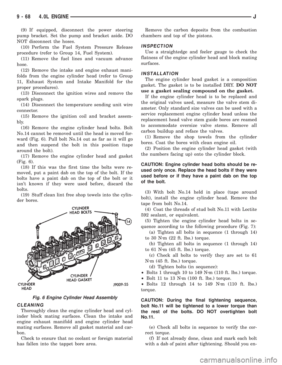
(16) Remove the engine cylinder head bolts. Bolt
No.14 cannot be removed until the head is moved for-
ward (Fig. 6). Pull bolt No.14 out as far as it will go
and then suspend the bolt in this position (tape
around the bolt).
(17) Remove the engine cylinder head and gasket
(Fig. 6).
(18) If this was the first time the bolts were re-
moved, put a paint dab on the top of the bolt. If the
bolts have a paint dab on the top of the bolt or it
isn't known if they were used before, discard the
bolts.
(19) Stuff clean lint free shop towels into the cylin-
der bores.
CLEANING
Thoroughly clean the engine cylinder head and cyl-
inder block mating surfaces. Clean the intake and
engine exhaust manifold and engine cylinder head
mating surfaces. Remove all gasket material and car-
bon.
Check to ensure that no coolant or foreign material
has fallen into the tappet bore area.Remove the carbon deposits from the combustion
chambers and top of the pistons.
INSPECTION
Use a straightedge and feeler gauge to check the
flatness of the engine cylinder head and block mating
surfaces.
INSTALLATION
The engine cylinder head gasket is a composition
gasket. The gasket is to be installed DRY.DO NOT
use a gasket sealing compound on the gasket.
If the engine cylinder head is to be replaced and
the original valves used, measure the valve stem di-
ameter. Only standard size valves can be used with a
service replacement engine cylinder head unless the
replacement head valve stem guide bores are reamed
to accommodate oversize valve stems. Remove all
carbon buildup and reface the valves.
(1) Remove the shop towels from the cylinder
bores. Coat the bores with clean engine oil.
(2) Position the engine cylinder head gasket (with
the numbers facing up) onto the cylinder block.
CAUTION: Engine cylinder head bolts should be re-
used only once. Replace the head bolts if they were
used before or if they have a paint dab on the top
of the bolt.
(3) With bolt No.14 held in place (tape around
bolt), install the engine cylinder head. Remove the
tape from bolt No.14.
(4) Coat the threads of stud bolt No.11 with Loctite
592 sealant, or equivalent.
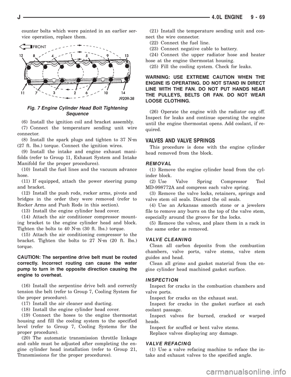
(5) Tighten the engine cylinder head bolts in se-
quence according to the following procedure (Fig. 7):
(a) Tighten all bolts in sequence (1 through 14)
to 30 Nzm (22 ft. lbs.) torque.
(b) Tighten all bolts in sequence (1 through 14)
to 61 Nzm (45 ft. lbs.) torque.
(c) Check all bolts to verify they are set to 61
Nzm (45 ft. lbs.) torque.
(d) Tighten bolts (in sequence):
²Bolts 1 through 10 to 149 Nzm (110 ft. lbs.) torque.
²Bolt 11 to 13 Nzm (100 ft. lbs.) torque.
²Bolts 12 through 14 to 149 Nzm (110 ft. lbs.)
torque.
CAUTION: During the final tightening sequence,
bolt No.11 will be tightened to a lower torque than
the rest of the bolts. DO NOT overtighten bolt
No.11.
(e) Check all bolts in sequence to verify the cor-
rect torque.
(f) If not already done, clean and mark each bolt
with a dab of paint after tightening. Should you en-
Fig. 6 Engine Cylinder Head Assembly
9 - 68 4.0L ENGINEJ
Page 1348 of 2158
counter bolts which were painted in an earlier ser-
vice operation, replace them.
(6) Install the ignition coil and bracket assembly.
(7) Connect the temperature sending unit wire
connector.
(8) Install the spark plugs and tighten to 37 Nzm
(27 ft. lbs.) torque. Connect the ignition wires.
(9) Install the intake and engine exhaust mani-
folds (refer to Group 11, Exhaust System and Intake
Manifold for the proper procedures).
(10) Install the fuel lines and the vacuum advance
hose.
(11) If equipped, attach the power steering pump
and bracket.
(12) Install the push rods, rocker arms, pivots and
bridges in the order they were removed (refer to
Rocker Arms and Push Rods in this section).
(13) Install the engine cylinder head cover.
(14) Attach the air conditioner compressor mount-
ing bracket to the engine cylinder head and block.
Tighten the bolts to 40 Nzm (30 ft. lbs.) torque.
(15) Attach the air conditioning compressor to the
bracket. Tighten the bolts to 27 Nzm (20 ft. lbs.)
torque.
CAUTION: The serpentine drive belt must be routed
correctly. Incorrect routing can cause the water
pump to turn in the opposite direction causing the
engine to overheat.
(16) Install the serpentine drive belt and correctly
tension the belt (refer to Group 7, Cooling System for
the proper procedure).
(17) Install the air cleaner and ducting.
(18) Install the engine cylinder head cover.
(19) Connect the hoses to the engine thermostat
housing and fill the cooling system to the specified
level (refer to Group 7, Cooling Systems for the
proper procedure).
(20) The automatic transmission throttle linkage
and cable must be adjusted after completing the en-
gine cylinder head installation (refer to Group 21,
Transmissions for the proper procedures).(21) Install the temperature sending unit and con-
nect the wire connector.
(22) Connect the fuel line.
(23) Connect negative cable to battery.
(24) Connect the upper radiator hose and heater
hose at the engine thermostat housing.
(25) Fill the cooling system. Check for leaks.
WARNING: USE EXTREME CAUTION WHEN THE
ENGINE IS OPERATING. DO NOT STAND IN DIRECT
LINE WITH THE FAN. DO NOT PUT HANDS NEAR
THE PULLEYS, BELTS OR FAN. DO NOT WEAR
LOOSE CLOTHING.
(26) Operate the engine with the radiator cap off.
Inspect for leaks and continue operating the engine
until the engine thermostat opens. Add coolant, if re-
quired.
VALVES AND VALVE SPRINGS
This procedure is done with the engine cylinder
head removed from the block.
REMOVAL
(1) Remove the engine cylinder head from the cyl-
inder block.
(2) Use Valve Spring Compressor Tool
MD-998772A and compress each valve spring.
(3) Remove the valve locks, retainers, springs and
valve stem oil seals. Discard the oil seals.
(4) Use an Arkansas smooth stone or a jewelers
file to remove any burrs on the top of the valve stem,
especially around the groove for the locks.
(5) Remove the valves, and place them in a rack in
the same order as removed.
VALVE CLEANING
Clean all carbon deposits from the combustion
chambers, valve ports, valve stems, valve stem
guides and head.
Clean all grime and gasket material from the en-
gine cylinder head machined gasket surface.
INSPECTION
Inspect for cracks in the combustion chambers and
valve ports.
Inspect for cracks on the exhaust seat.
Inspect for cracks in the gasket surface at each
coolant passage.
Inspect valves for burned, cracked or warped
heads.
Inspect for scuffed or bent valve stems.
Replace valves displaying any damage.
VALVE REFACING
(1) Use a valve refacing machine to reface the in-
take and exhaust valves to the specified angle.
Fig. 7 Engine Cylinder Head Bolt Tightening
Sequence
J4.0L ENGINE 9 - 69
Page 1349 of 2158
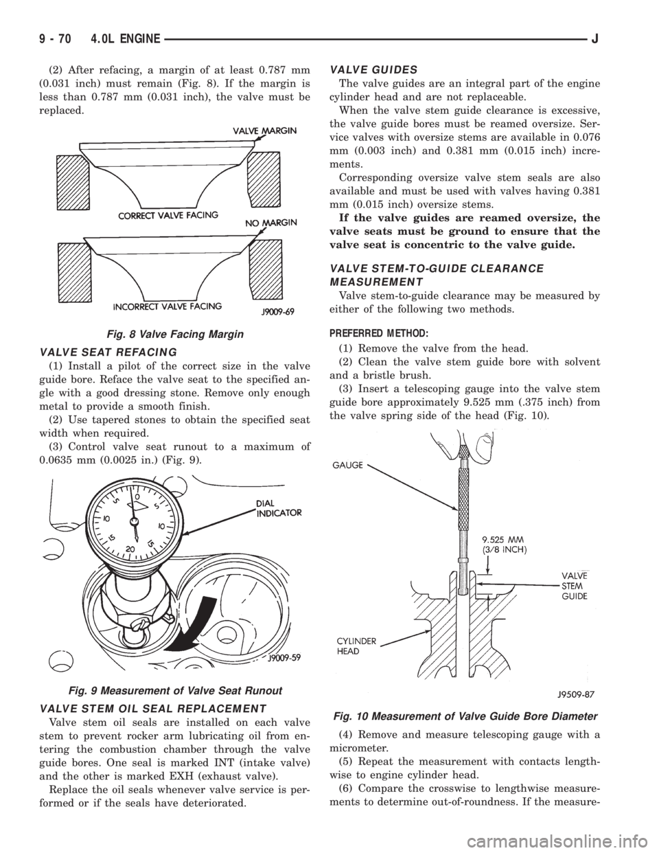
(2) After refacing, a margin of at least 0.787 mm
(0.031 inch) must remain (Fig. 8). If the margin is
less than 0.787 mm (0.031 inch), the valve must be
replaced.
VALVE SEAT REFACING
(1) Install a pilot of the correct size in the valve
guide bore. Reface the valve seat to the specified an-
gle with a good dressing stone. Remove only enough
metal to provide a smooth finish.
(2) Use tapered stones to obtain the specified seat
width when required.
(3) Control valve seat runout to a maximum of
0.0635 mm (0.0025 in.) (Fig. 9).
VALVE STEM OIL SEAL REPLACEMENT
Valve stem oil seals are installed on each valve
stem to prevent rocker arm lubricating oil from en-
tering the combustion chamber through the valve
guide bores. One seal is marked INT (intake valve)
and the other is marked EXH (exhaust valve).
Replace the oil seals whenever valve service is per-
formed or if the seals have deteriorated.
VALVE GUIDES
The valve guides are an integral part of the engine
cylinder head and are not replaceable.
When the valve stem guide clearance is excessive,
the valve guide bores must be reamed oversize. Ser-
vice valves with oversize stems are available in 0.076
mm (0.003 inch) and 0.381 mm (0.015 inch) incre-
ments.
Corresponding oversize valve stem seals are also
available and must be used with valves having 0.381
mm (0.015 inch) oversize stems.
If the valve guides are reamed oversize, the
valve seats must be ground to ensure that the
valve seat is concentric to the valve guide.
VALVE STEM-TO-GUIDE CLEARANCE
MEASUREMENT
Valve stem-to-guide clearance may be measured by
either of the following two methods.
PREFERRED METHOD:
(1) Remove the valve from the head.
(2) Clean the valve stem guide bore with solvent
and a bristle brush.
(3) Insert a telescoping gauge into the valve stem
guide bore approximately 9.525 mm (.375 inch) from
the valve spring side of the head (Fig. 10).
(4) Remove and measure telescoping gauge with a
micrometer.
(5) Repeat the measurement with contacts length-
wise to engine cylinder head.
(6) Compare the crosswise to lengthwise measure-
ments to determine out-of-roundness. If the measure-
Fig. 10 Measurement of Valve Guide Bore Diameter
Fig. 8 Valve Facing Margin
Fig. 9 Measurement of Valve Seat Runout
9 - 70 4.0L ENGINEJ
Page 1356 of 2158
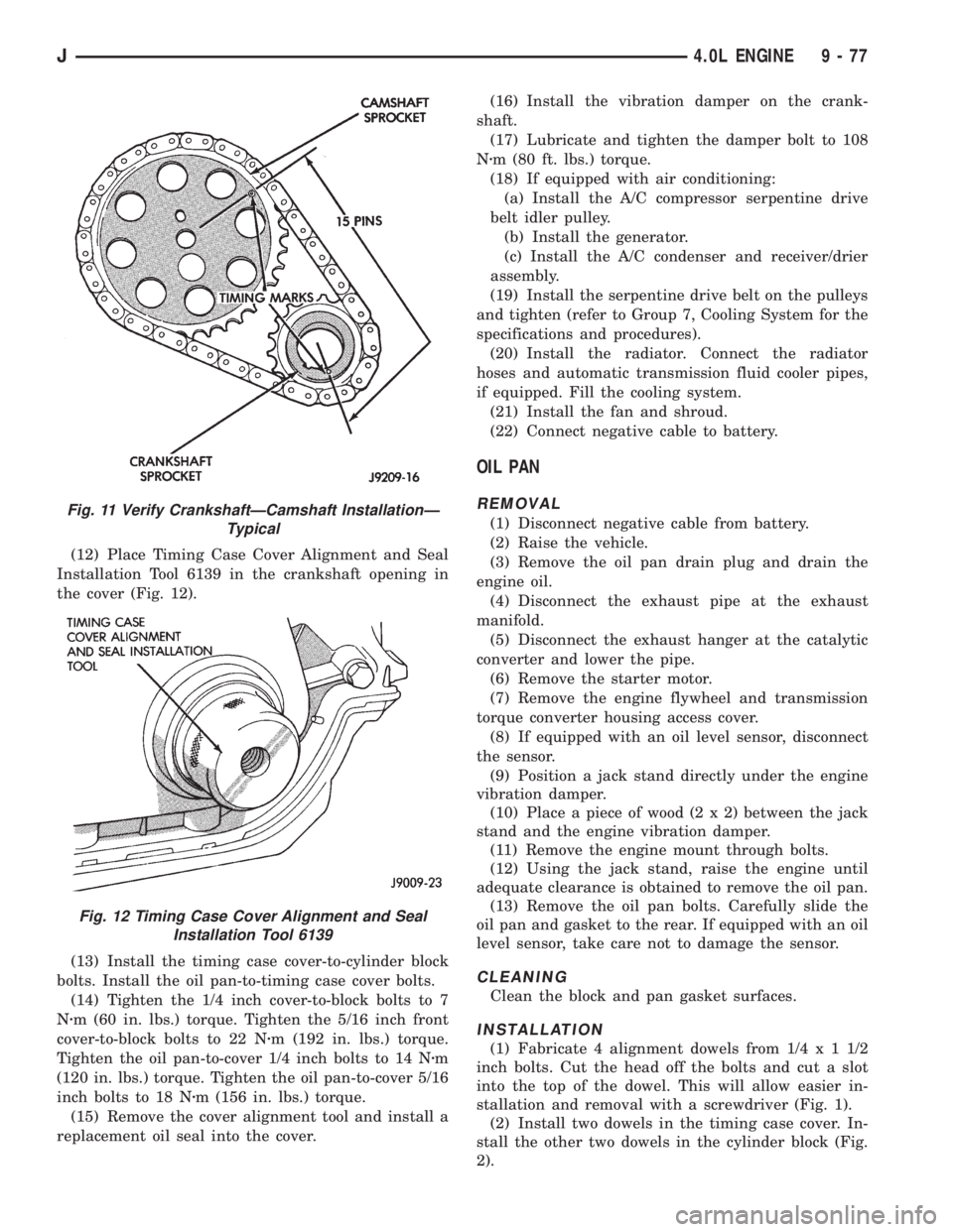
(12) Place Timing Case Cover Alignment and Seal
Installation Tool 6139 in the crankshaft opening in
the cover (Fig. 12).
(13) Install the timing case cover-to-cylinder block
bolts. Install the oil pan-to-timing case cover bolts.
(14) Tighten the 1/4 inch cover-to-block bolts to 7
Nzm (60 in. lbs.) torque. Tighten the 5/16 inch front
cover-to-block bolts to 22 Nzm (192 in. lbs.) torque.
Tighten the oil pan-to-cover 1/4 inch bolts to 14 Nzm
(120 in. lbs.) torque. Tighten the oil pan-to-cover 5/16
inch bolts to 18 Nzm (156 in. lbs.) torque.
(15) Remove the cover alignment tool and install a
replacement oil seal into the cover.(16) Install the vibration damper on the crank-
shaft.
(17) Lubricate and tighten the damper bolt to 108
Nzm (80 ft. lbs.) torque.
(18) If equipped with air conditioning:
(a) Install the A/C compressor serpentine drive
belt idler pulley.
(b) Install the generator.
(c) Install the A/C condenser and receiver/drier
assembly.
(19) Install the serpentine drive belt on the pulleys
and tighten (refer to Group 7, Cooling System for the
specifications and procedures).
(20) Install the radiator. Connect the radiator
hoses and automatic transmission fluid cooler pipes,
if equipped. Fill the cooling system.
(21) Install the fan and shroud.
(22) Connect negative cable to battery.
OIL PAN
REMOVAL
(1) Disconnect negative cable from battery.
(2) Raise the vehicle.
(3) Remove the oil pan drain plug and drain the
engine oil.
(4) Disconnect the exhaust pipe at the exhaust
manifold.
(5) Disconnect the exhaust hanger at the catalytic
converter and lower the pipe.
(6) Remove the starter motor.
(7) Remove the engine flywheel and transmission
torque converter housing access cover.
(8) If equipped with an oil level sensor, disconnect
the sensor.
(9) Position a jack stand directly under the engine
vibration damper.
(10) Place a piece of wood (2 x 2) between the jack
stand and the engine vibration damper.
(11) Remove the engine mount through bolts.
(12) Using the jack stand, raise the engine until
adequate clearance is obtained to remove the oil pan.
(13) Remove the oil pan bolts. Carefully slide the
oil pan and gasket to the rear. If equipped with an oil
level sensor, take care not to damage the sensor.
CLEANING
Clean the block and pan gasket surfaces.
INSTALLATION
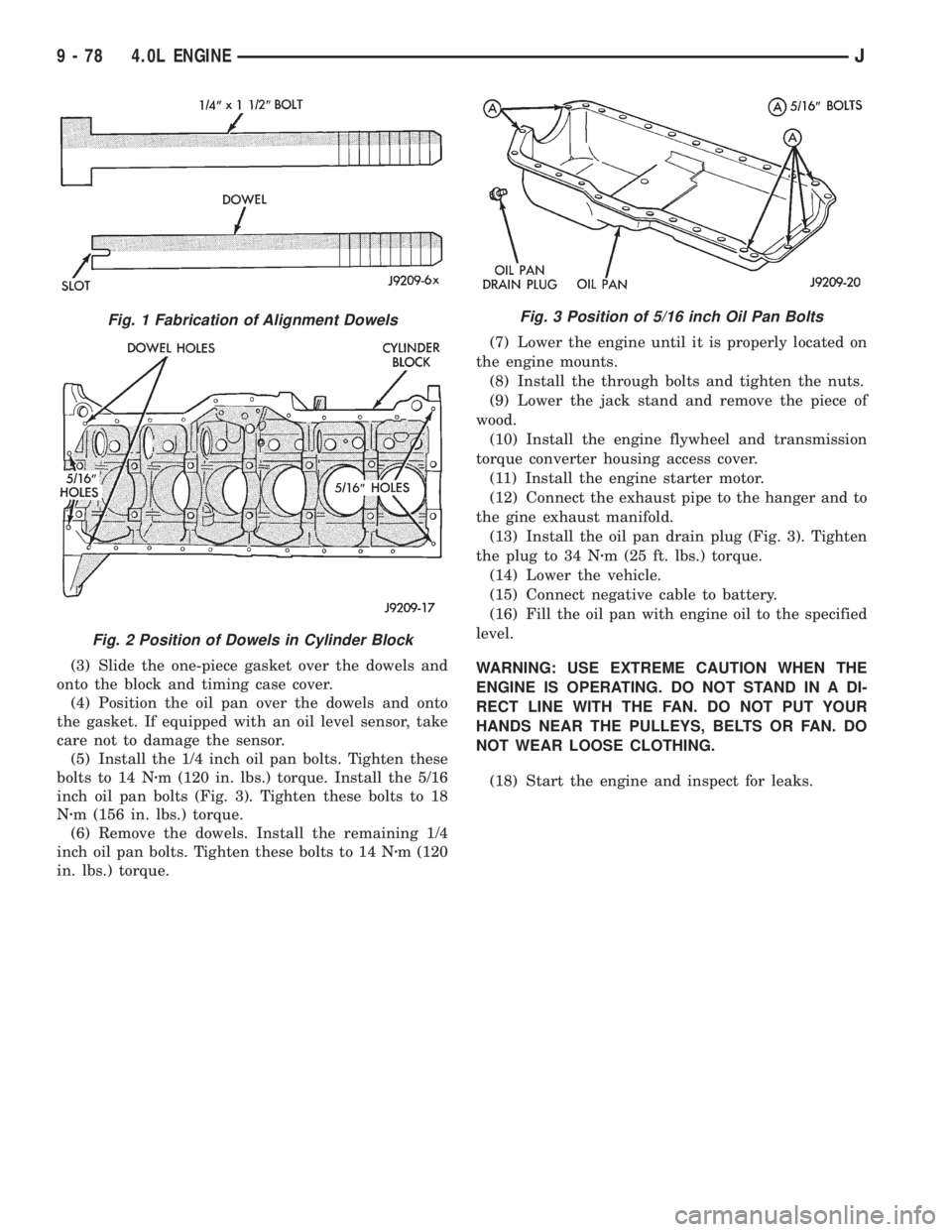
(1) Fabricate 4 alignment dowels from 1/4 x 1 1/2
inch bolts. Cut the head off the bolts and cut a slot
into the top of the dowel. This will allow easier in-
stallation and removal with a screwdriver (Fig. 1).
(2) Install two dowels in the timing case cover. In-
stall the other two dowels in the cylinder block (Fig.
2).
Fig. 11 Verify CrankshaftÐCamshaft InstallationÐ
Typical
Fig. 12 Timing Case Cover Alignment and Seal
Installation Tool 6139
J4.0L ENGINE 9 - 77
Page 1357 of 2158
(3) Slide the one-piece gasket over the dowels and
onto the block and timing case cover.
(4) Position the oil pan over the dowels and onto
the gasket. If equipped with an oil level sensor, take
care not to damage the sensor.
(5) Install the 1/4 inch oil pan bolts. Tighten these
bolts to 14 Nzm (120 in. lbs.) torque. Install the 5/16
inch oil pan bolts (Fig. 3). Tighten these bolts to 18
Nzm (156 in. lbs.) torque.
(6) Remove the dowels. Install the remaining 1/4
inch oil pan bolts. Tighten these bolts to 14 Nzm (120
in. lbs.) torque.(7) Lower the engine until it is properly located on
the engine mounts.
(8) Install the through bolts and tighten the nuts.
(9) Lower the jack stand and remove the piece of
wood.
(10) Install the engine flywheel and transmission
torque converter housing access cover.
(11) Install the engine starter motor.
(12) Connect the exhaust pipe to the hanger and to
the gine exhaust manifold.
(13) Install the oil pan drain plug (Fig. 3). Tighten
the plug to 34 Nzm (25 ft. lbs.) torque.
(14) Lower the vehicle.
(15) Connect negative cable to battery.
(16) Fill the oil pan with engine oil to the specified
level.
WARNING: USE EXTREME CAUTION WHEN THE
ENGINE IS OPERATING. DO NOT STAND IN A DI-
RECT LINE WITH THE FAN. DO NOT PUT YOUR
HANDS NEAR THE PULLEYS, BELTS OR FAN. DO
NOT WEAR LOOSE CLOTHING.
(18) Start the engine and inspect for leaks.
Fig. 1 Fabrication of Alignment Dowels
Fig. 2 Position of Dowels in Cylinder Block
Fig. 3 Position of 5/16 inch Oil Pan Bolts
9 - 78 4.0L ENGINEJ
Page 1376 of 2158
EXHAUST SYSTEM AND INTAKE MANIFOLD
CONTENTS
page page
EXHAUST SYSTEM....................... 1
EXHAUST SYSTEM DIAGNOSIS............. 2SERVICE PROCEDURES................... 3
TORQUE SPECIFICATIONS................ 10
EXHAUST SYSTEM
GENERAL INFORMATION
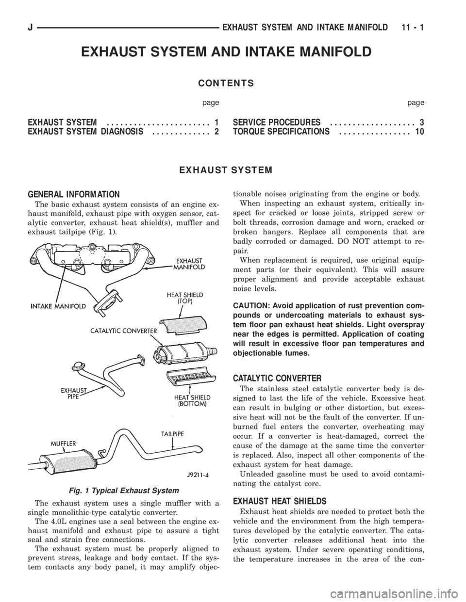
The basic exhaust system consists of an engine ex-
haust manifold, exhaust pipe with oxygen sensor, cat-
alytic converter, exhaust heat shield(s), muffler and
exhaust tailpipe (Fig. 1).
The exhaust system uses a single muffler with a
single monolithic-type catalytic converter.
The 4.0L engines use a seal between the engine ex-
haust manifold and exhaust pipe to assure a tight
seal and strain free connections.
The exhaust system must be properly aligned to
prevent stress, leakage and body contact. If the sys-
tem contacts any body panel, it may amplify objec-tionable noises originating from the engine or body.
When inspecting an exhaust system, critically in-
spect for cracked or loose joints, stripped screw or
bolt threads, corrosion damage and worn, cracked or
broken hangers. Replace all components that are
badly corroded or damaged. DO NOT attempt to re-
pair.
When replacement is required, use original equip-
ment parts (or their equivalent). This will assure
proper alignment and provide acceptable exhaust
noise levels.
CAUTION: Avoid application of rust prevention com-
pounds or undercoating materials to exhaust sys-
tem floor pan exhaust heat shields. Light overspray
near the edges is permitted. Application of coating
will result in excessive floor pan temperatures and
objectionable fumes.
CATALYTIC CONVERTER
The stainless steel catalytic converter body is de-
signed to last the life of the vehicle. Excessive heat
can result in bulging or other distortion, but exces-
sive heat will not be the fault of the converter. If un-
burned fuel enters the converter, overheating may
occur. If a converter is heat-damaged, correct the
cause of the damage at the same time the converter
is replaced. Also, inspect all other components of the
exhaust system for heat damage.
Unleaded gasoline must be used to avoid contami-
nating the catalyst core.
EXHAUST HEAT SHIELDS
Exhaust heat shields are needed to protect both the
vehicle and the environment from the high tempera-
tures developed by the catalytic converter. The cata-
lytic converter releases additional heat into the
exhaust system. Under severe operating conditions,
the temperature increases in the area of the con-
Fig. 1 Typical Exhaust System
JEXHAUST SYSTEM AND INTAKE MANIFOLD 11 - 1
Page 1377 of 2158
verter. Such conditions can exist when the engine
misfires or otherwise does not operate at peak effi-
ciency.
DO NOT remove spark plug wires from plugs or by
any other means short out cylinders. Failure of the
catalytic converter can occur due to a temperature
increase caused by unburned fuel passing through
the converter.DO NOT allow the engine to operate at fast idle for
extended periods (over 5 minutes). This condition
may result in excessive temperatures in the exhaust
system and on the floor pan.
EXHAUST SYSTEM DIAGNOSIS
11 - 2 EXHAUST SYSTEM AND INTAKE MANIFOLDJ