1995 JEEP XJ Exhaust
[x] Cancel search: ExhaustPage 257 of 2158
temperature, coolant is allowed to flow to the radia-
tor. This provides quick engine warmup and overall
temperature control.
An arrow plus the wordUPis stamped on the
front flange next to the air bleed. The wordsTO
RADare stamped on one arm of the thermostat.
They indicate the proper installed position.
The same thermostat is used for winter and sum-
mer seasons. An engine should not be operated with-
out a thermostat, except for servicing or testing.
Operating without a thermostat causes other prob-
lems. These are: longer engine warmup time, unreli-
able warmup performance, increased exhaust
emissions and crankcase condensation. This conden-
sation can result in sludge formation.
CAUTION: Do not operate an engine without a ther-
mostat, except for servicing or testing.
ON-BOARD DIAGNOSTICS
XJ and YJ models are equipped with On-Board Di-
agnostics for certain cooling system components. Re-
fer to On-Board Diagnostics (OBD) in the Diagnosis
section of this group for additional information. If the
powertrain control module (PCM) detects low engine
coolant temperature, it will record a Diagnostic Trou-
ble Code (DTC) in the PCM memory. The DTC num-
ber for low coolant temperature is 17. Do not change
a thermostat for lack of heat as indicated by the in-
strument panel gauge or heater performance unless a
DTC number 17 is present. Refer to the Diagnosis
section of this group for other probable causes. For
other DTC numbers, refer to On-Board Diagnostics
in the General Diagnosis section of Group 14, Fuel
Systems.
The DTC can also be accessed through the DRB
scan tool. Refer to the appropriate Powertrain Diag-
nostic Procedures manual for diagnostic information
and operation of the DRB scan tool.
REMOVAL
WARNING: DO NOT LOOSEN THE RADIATOR
DRAINCOCK WITH THE SYSTEM HOT AND PRES-
SURIZED. SERIOUS BURNS FROM THE COOLANT
CAN OCCUR.
DO NOT WASTE reusable coolant. If the solution
is clean, drain the coolant into a clean container for
reuse.
(1) Drain the coolant from the radiator until the
level is below the thermostat housing.
WARNING: CONSTANT TENSION HOSE CLAMPS
ARE USED ON MOST COOLING SYSTEM HOSES.
WHEN REMOVING OR INSTALLING, USE ONLY
TOOLS DESIGNED FOR SERVICING THIS TYPE OF
CLAMP, SUCH AS SPECIAL CLAMP TOOL (NUMBER
6094) (FIG. 15). SNAP-ON CLAMP TOOL (NUMBER
HPC-20) MAY BE USED FOR LARGER CLAMPS. AL-
WAYS WEAR SAFETY GLASSES WHEN SERVICING
CONSTANT TENSION CLAMPS.
CAUTION: A number or letter is stamped into the
tongue of constant tension clamps (Fig. 16). If re-
placement is necessary, use only an original equip-
ment clamp with matching number or letter.
(2) Remove radiator upper hose and heater hose at
thermostat housing.
(3) Disconnect wiring connector at engine coolant
temperature sensor.
(4) Remove thermostat housing mounting bolts,
thermostat housing, gasket and thermostat (Fig. 17).
Discard old gasket.
(5) Clean the gasket mating surfaces.
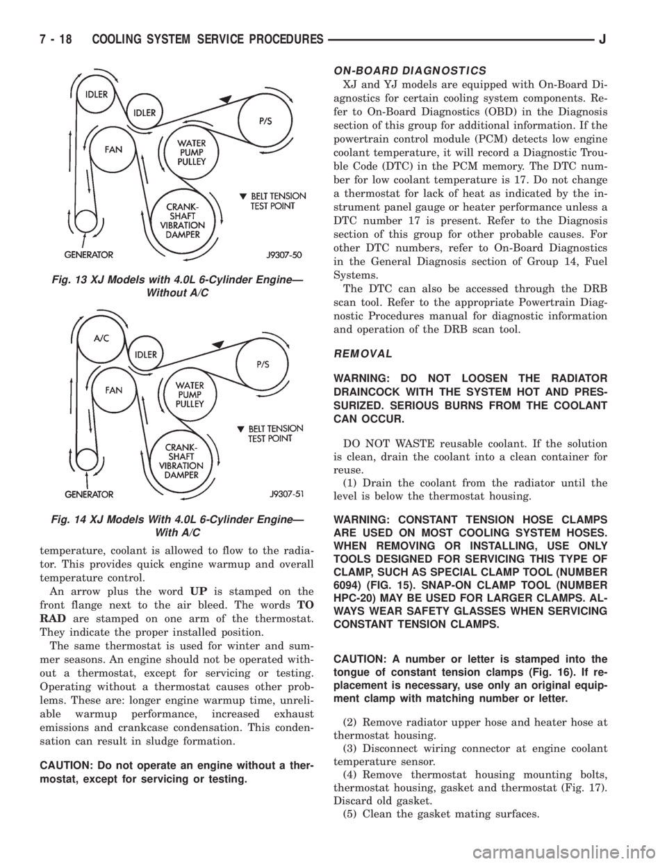
Fig. 13 XJ Models with 4.0L 6-Cylinder EngineÐ
Without A/C
Fig. 14 XJ Models With 4.0L 6-Cylinder EngineÐ
With A/C
7 - 18 COOLING SYSTEM SERVICE PROCEDURESJ
Page 271 of 2158
(10) Check and adjust automatic transmission
fluid level (if equipped).
COOLING SYSTEM HOSES
Rubber hoses route coolant to and from the radia-
tor, intake manifold and heater core. All XJ models
equipped with air conditioning have a coolant control
valve. This is located in-line with the heater core in-
let and outlet hoses. It controls coolant flow to the
heater core when the air conditioning system is in
operation.
Radiator lower hoses are spring-reinforced to pre-
vent collapse from water pump suction at moderate
and high engine speeds.
WARNING: CONSTANT TENSION HOSE CLAMPS
ARE USED ON MOST COOLING SYSTEM HOSES.
WHEN REMOVING OR INSTALLING, USE ONLY
TOOLS DESIGNED FOR SERVICING THIS TYPE OF
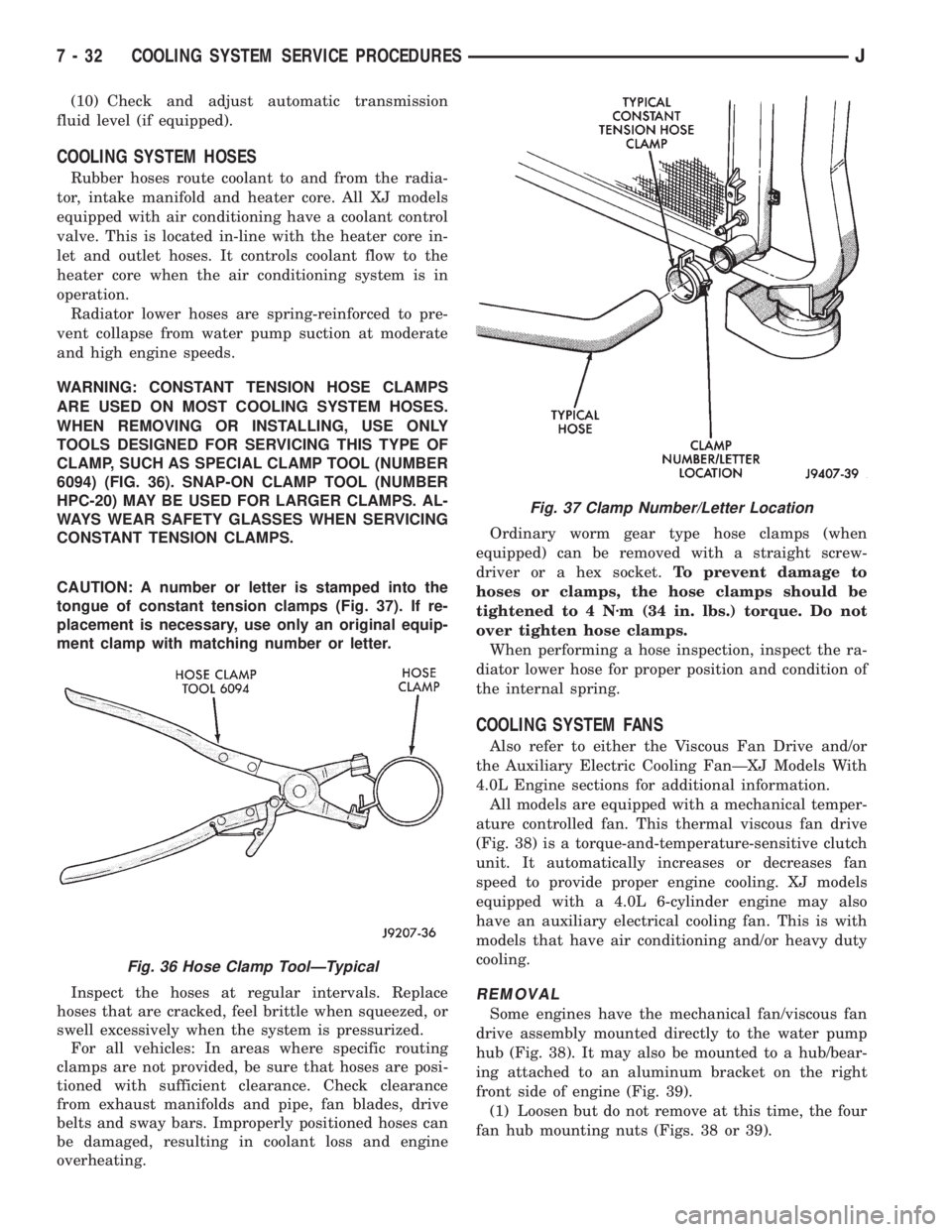
CLAMP, SUCH AS SPECIAL CLAMP TOOL (NUMBER
6094) (FIG. 36). SNAP-ON CLAMP TOOL (NUMBER
HPC-20) MAY BE USED FOR LARGER CLAMPS. AL-
WAYS WEAR SAFETY GLASSES WHEN SERVICING
CONSTANT TENSION CLAMPS.
CAUTION: A number or letter is stamped into the
tongue of constant tension clamps (Fig. 37). If re-
placement is necessary, use only an original equip-
ment clamp with matching number or letter.
Inspect the hoses at regular intervals. Replace
hoses that are cracked, feel brittle when squeezed, or
swell excessively when the system is pressurized.
For all vehicles: In areas where specific routing
clamps are not provided, be sure that hoses are posi-
tioned with sufficient clearance. Check clearance
from exhaust manifolds and pipe, fan blades, drive
belts and sway bars. Improperly positioned hoses can
be damaged, resulting in coolant loss and engine
overheating.Ordinary worm gear type hose clamps (when
equipped) can be removed with a straight screw-
driver or a hex socket.To prevent damage to
hoses or clamps, the hose clamps should be
tightened to 4 Nzm (34 in. lbs.) torque. Do not
over tighten hose clamps.
When performing a hose inspection, inspect the ra-
diator lower hose for proper position and condition of
the internal spring.
COOLING SYSTEM FANS
Also refer to either the Viscous Fan Drive and/or
the Auxiliary Electric Cooling FanÐXJ Models With
4.0L Engine sections for additional information.
All models are equipped with a mechanical temper-
ature controlled fan. This thermal viscous fan drive
(Fig. 38) is a torque-and-temperature-sensitive clutch
unit. It automatically increases or decreases fan
speed to provide proper engine cooling. XJ models
equipped with a 4.0L 6-cylinder engine may also
have an auxiliary electrical cooling fan. This is with
models that have air conditioning and/or heavy duty
cooling.
REMOVAL
Some engines have the mechanical fan/viscous fan
drive assembly mounted directly to the water pump
hub (Fig. 38). It may also be mounted to a hub/bear-
ing attached to an aluminum bracket on the right
front side of engine (Fig. 39).
(1) Loosen but do not remove at this time, the four
fan hub mounting nuts (Figs. 38 or 39).
Fig. 36 Hose Clamp ToolÐTypical
Fig. 37 Clamp Number/Letter Location
7 - 32 COOLING SYSTEM SERVICE PROCEDURESJ
Page 283 of 2158
ENGINE BLOCK HEATER
GENERAL INFORMATION
DESCRIPTION AND OPERATION
An optional engine block heater is available for all
models. The heater is equipped with a power cord.
The cord is attached to an engine compartment com-
ponent with tie-straps. The heater warms the engine
providing easier engine starting and faster warm-up
in low temperatures. The heater is mounted in a core
hole of the engine cylinder block (in place of a freeze
plug) with the heating element immersed in engine
coolant. Connect the power cord to a grounded 110-
120 volt AC electrical outlet with a grounded, three-
wire extension cord.
WARNING: DO NOT OPERATE ENGINE UNLESS
BLOCK HEATER CORD HAS BEEN DISCONNECTED
FROM POWER SOURCE AND SECURED IN PLACE.
BLOCK HEATER SPECIFICATIONS
²2.5L 4-Cylinder Engine: 115 Volts 400 Watts
²4.0L 6-Cylinder Engine: 120 Volts 600 Watts
REMOVAL
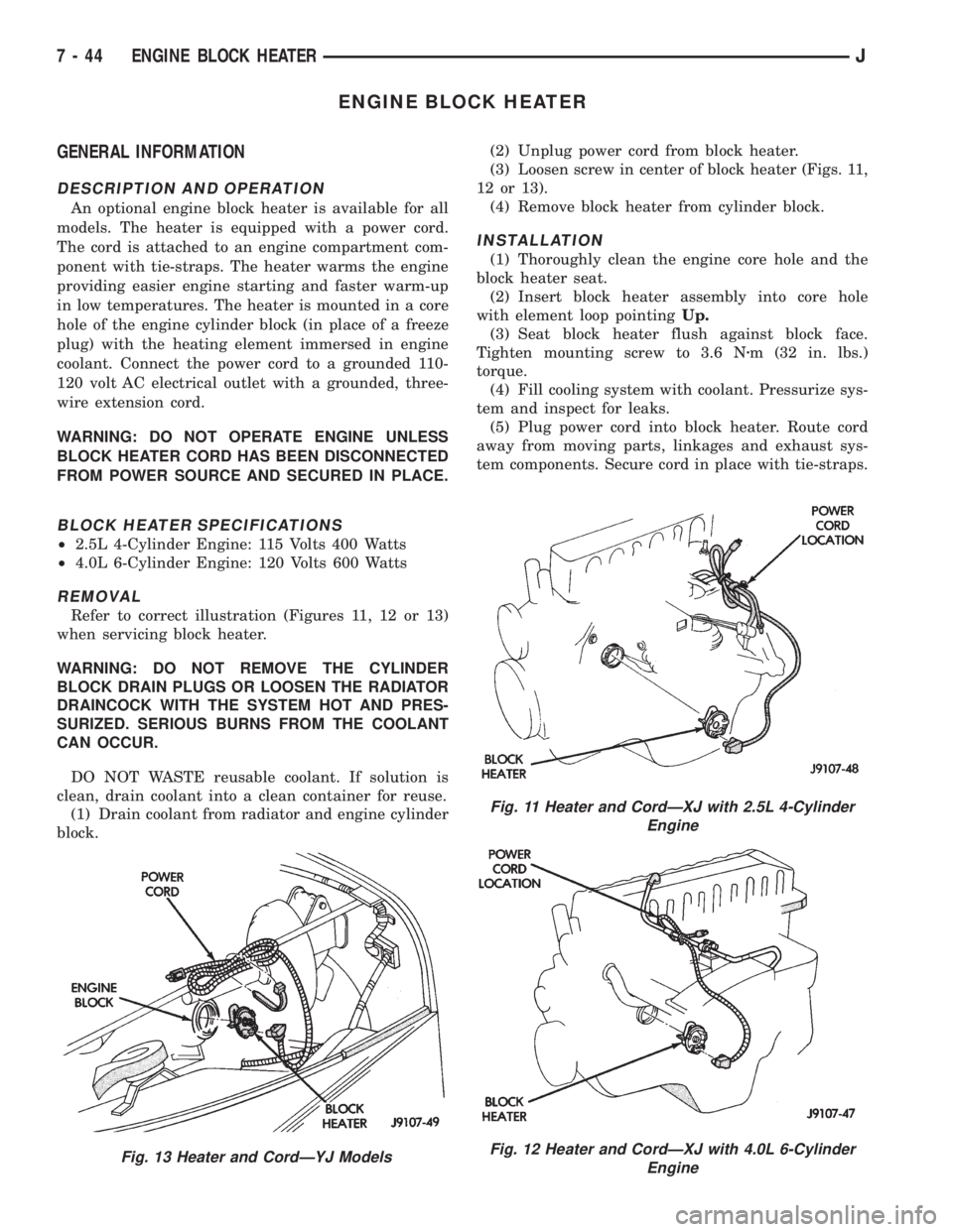
Refer to correct illustration (Figures 11, 12 or 13)
when servicing block heater.
WARNING: DO NOT REMOVE THE CYLINDER
BLOCK DRAIN PLUGS OR LOOSEN THE RADIATOR
DRAINCOCK WITH THE SYSTEM HOT AND PRES-
SURIZED. SERIOUS BURNS FROM THE COOLANT
CAN OCCUR.
DO NOT WASTE reusable coolant. If solution is
clean, drain coolant into a clean container for reuse.
(1) Drain coolant from radiator and engine cylinder
block.(2) Unplug power cord from block heater.
(3) Loosen screw in center of block heater (Figs. 11,
12 or 13).
(4) Remove block heater from cylinder block.
INSTALLATION
(1) Thoroughly clean the engine core hole and the
block heater seat.
(2) Insert block heater assembly into core hole
with element loop pointingUp.
(3) Seat block heater flush against block face.
Tighten mounting screw to 3.6 Nzm (32 in. lbs.)
torque.
(4) Fill cooling system with coolant. Pressurize sys-
tem and inspect for leaks.
(5) Plug power cord into block heater. Route cord
away from moving parts, linkages and exhaust sys-
tem components. Secure cord in place with tie-straps.
Fig. 13 Heater and CordÐYJ Models
Fig. 11 Heater and CordÐXJ with 2.5L 4-Cylinder
Engine
Fig. 12 Heater and CordÐXJ with 4.0L 6-Cylinder
Engine
7 - 44 ENGINE BLOCK HEATERJ
Page 312 of 2158
CAUTION: Be certain that battery cables are con-
nected to the correct battery terminals. Reverse po-
larity can damage electrical components.
(12) Place oiled felt washer on battery positive ter-
minal post.
(13) Install and tighten battery positive cable ter-
minal clamp. Then install and tighten negative cableterminal clamp. Both cable clamp bolts require
torque of 8.5 Nzm (75 in. lbs.).
(14) Apply a thin coating of petroleum jelly or
chassis grease to cable terminals and battery posts.
STARTER AND STARTER RELAY
GENERAL INFORMATION
This section covers starter and starter relay service
procedures only. For diagnostic procedures, refer to
Group 8A - Battery/Starting/Charging Systems Diag-
nostics. Service procedures for other starting system
components can be found as follows:
²battery - see Battery, in this group
²ignition switch - refer to Group 8D - Ignition Sys-
tems
²park/neutral position switch (automatic transmis-
sion) - refer to Group 21 - Transmission and Transfer
Case
²wiring harness and connectors - refer to Group 8W
- Wiring Diagrams.
STARTER
The starter motor incorporates several features to
create a reliable, efficient, compact and lightweight
unit. A planetary gear system (intermediate trans-
mission) is used between the electric motor and pin-
ion gear. This feature makes it possible to reduce the
dimensions of the starter. At the same time, it allows
higher armature rotational speed and delivers in-
creased torque through the pinion gear to the fly-
wheel or drive plate ring gear.
The use of a permanent magnet field also reduces
starter size and weight. This field consists of six
high-strength permanent magnets. The magnets are
aligned according to their polarity and are perma-
nently fixed in the starter field frame.
The starter motors for all engines are activated by
a solenoid mounted to the overrunning clutch hous-
ing. However, the starter motor/solenoid are serviced
only as a complete assembly. If either component
fails, the entire assembly must be replaced.
This unit is highly sensitive to hammering, shocks
and external pressure.
CAUTION: The starter motor MUST NOT BE
CLAMPED in a vise by the starter field frame. Doing
so may damage the magnets. It may be clamped by
the mounting flange ONLY.CAUTION: Do not connect starter motor incorrectly
when tests are being performed. The permanent
magnets may be damaged and rendered unservice-
able.
STARTER RELAY
The starter relay is an International Standards Or-
ganization (ISO) type relay, and is located in the
Power Distribution Center (PDC). Refer to underside
of PDC cover for relay location.
STARTER REMOVE/INSTALLÐ2.5L
XJ MODELS
(1) Disconnect battery negative cable.
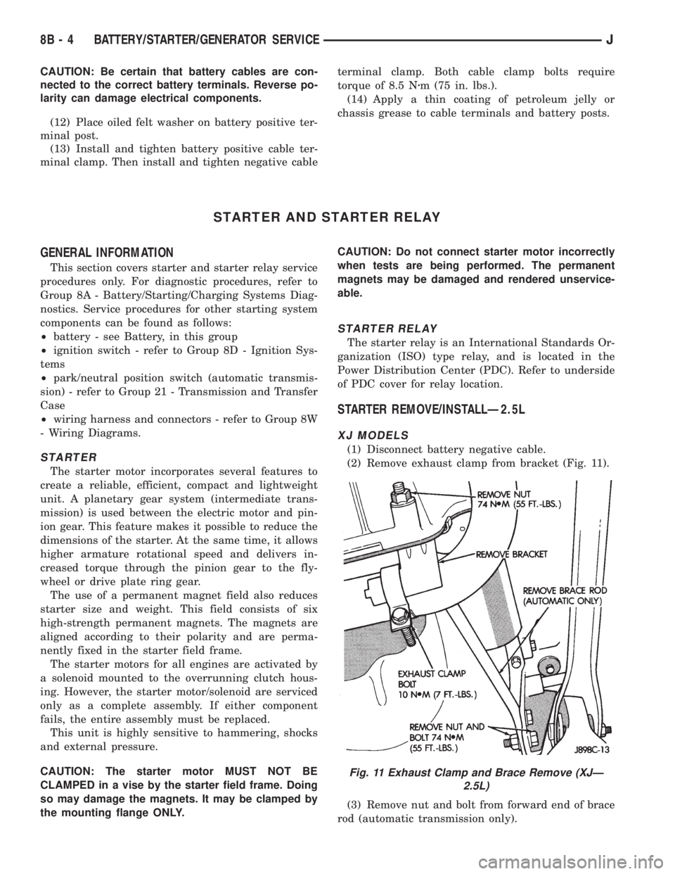
(2) Remove exhaust clamp from bracket (Fig. 11).
(3) Remove nut and bolt from forward end of brace
rod (automatic transmission only).
Fig. 11 Exhaust Clamp and Brace Remove (XJÐ
2.5L)
8B - 4 BATTERY/STARTER/GENERATOR SERVICEJ
Page 1281 of 2158
minutes). The use of a locating dowel is recom-
mended during assembly to prevent smearing the
material off location.
Mopar Gasket Maker should be applied sparingly
to one gasket surface. The sealant diameter should
be 1.00 mm (0.04 inch) or less. Be certain the mate-
rial surrounds each mounting hole. Excess material
can easily be wiped off. Components should be
torqued in place within 15 minutes. The use of a lo-
cating dowel is recommended during assembly to pre-
vent smearing the material off location.
ENGINE PERFORMANCE
To provide best vehicle performance and lowest ve-
hicle emissions, it is most important that the tune-up
be done accurately. Use the specifications listed on
the Vehicle Emission Control Information label found
on the engine compartment hood.
(1) Test battery specific gravity. Add water, if nec-
essary. Clean and tighten battery connections.
(2) Test cranking amperage draw (refer to Group
8B, Battery/Starter Service for the proper proce-
dures).
(3) Tighten the intake manifold bolts (refer to
Group 11, Exhaust System and Intake Manifold for
the proper specifications).
(4) Perform cylinder compression test:
(a) Check engine oil level and add oil, if neces-
sary.
(b) Drive the vehicle until engine reaches normal
operating temperature.
(c) Select a route free from traffic and other
forms of congestion, observe all traffic laws and
briskly accelerate through the gears several times.
The higher engine speed may help clean out valve
seat deposits which can prevent accurate compres-
sion readings.
CAUTION: DO NOT overspeed the engine.
(d) Remove all spark plugs from engine. As spark
plugs are being removed, check electrodes for ab-
normal firing indicatorsÐfouled, hot, oily, etc.
Record cylinder number of spark plug for future
reference.
(e) Disconnect coil wire from distributor and se-
cure to good ground to prevent a spark from start-
ing a fire.
(f) Be sure throttle blades are fully open during
the compression check.
(g) Insert compression gage adaptor into the
No.1 spark plug hole. Crank engine until maximum
pressure is reached on gauge. Record this pressure
as No.1 cylinder pressure.
(h) Repeat Step 4g for all remaining cylinders.
(i) Compression should not be less than 689 kPa
(100 psi) and not vary more than 172 kPa (25 psi)
from cylinder to cylinder.(j) If cylinder(s) have abnormally low compres-
sion pressures, repeat steps 4a through 4h.
(k) If the same cylinder(s) repeat an abnormally
low reading, it could indicate the existence of a
problem in the cylinder.
The recommended compression pressures are
to be used only as a guide to diagnosing engine
problems. An engine should NOT be disassem-
bled to determine the cause of low compression
unless some malfunction is present.
(5) Clean or replace spark plugs as necessary. Ad-
just gap (refer to Group 8D, Ignition System for gap
adjustment and torque).
(6) Test resistance of spark plug cables (refer to
Group 8D, Ignition System).
(7) Inspect the primary wire. Test coil output volt-
age, primary and secondary resistance. Replace parts
as necessary (refer to Group 8D, Ignition System and
make necessary adjustment).
(8) Perform a combustion analysis.
(9) Test fuel pump for pressure (refer to Group 14,
Fuel System for the proper specifications).
(10) Inspect air filter element (refer to Group 0,
Lubrication and Maintenance for the proper proce-
dure).
(11) Inspect crankcase ventilation system (refer to
Group 0, Lubrication and Maintenance for the proper
procedure).
(12) For emission controls refer to Group 25, Emis-
sion Controls System for service procedures.
(13) Inspect and adjust accessory belt drives (refer
to Group 7, Cooling System for the proper adjust-
ments).
(14) Road test vehicle as a final test.
HONING CYLINDER BORES
Before honing, stuff plenty of clean shop towels un-
der the bores and over the crankshaft to keep abra-
sive materials from entering the crankshaft area.
(1) Used carefully, the Cylinder Bore Sizing Hone
C-823 equipped with 220 grit stones, is the best tool
for this job. In addition to deglazing, it will reduce
taper and out-of-round as well as removing light
scuffing, scoring or scratches. Usually a few strokes
will clean up a bore and maintain the required lim-
its.
CAUTION: DO NOT use rigid type hones to remove
cylinder wall glaze.
(2) Deglazing of the cylinder walls may be done if
the cylinder bore is straight and round. Use a cylin-
der surfacing hone, Honing Tool C-3501, equipped
with 280 grit stones (C-3501-3810). 20-60 strokes, de-
pending on the bore condition, will be sufficient to
provide a satisfactory surface. Using honing oil
C-3501-3880 or a light honing oil available from ma-
jor oil distributors.
9 - 2 ENGINESJ
Page 1285 of 2158
CYLINDER COMBUSTION PRESSURE LEAKAGE
TEST
The combustion pressure leakage test provides an
accurate means for determining engine condition.
Combustion pressure leakage testing will detect:
²Exhaust and intake valve leaks (improper seat-
ing).
²Leaks between adjacent cylinders or into water
jacket.
²Any causes for combustion/compression pressure
loss.
WARNING: DO NOT REMOVE THE RADIATOR CAP
WITH THE SYSTEM HOT AND UNDER PRESSURE
BECAUSE SERIOUS BURNS FROM COOLANT CAN
OCCUR.
Check the coolant level and fill as required. DO
NOT install the radiator cap.
Start and operate the engine until it attains nor-
mal operating temperature, then turn the engine
OFF.
Remove the spark plugs.
Remove the oil filler cap.
Remove the air cleaner.
Calibrate the tester according to the manufactur-
er's instructions. The shop air source for testing
should maintain 483 kPa (70 psi) minimum, 1 379
kPa (200 psi) maximum and 552 kPa (80 psi) recom-
mended.
Perform the test procedures on each cylinder ac-
cording to the tester manufacturer's instructions.
While testing, listen for pressurized air escaping
through the throttle body, tailpipe and oil filler cap
opening. Check for bubbles in the radiator coolant.
All gauge pressure indications should be equal,
with no more than 25% leakage.
FOR EXAMPLE:At 552 kPa (80 psi) input pres-
sure, a minimum of 414 kPa (60 psi) should be main-
tained in the cylinder.
Refer to the Cylinder Combustion Pressure Leak-
age Test Diagnosis chart.
INSPECTION (ENGINE OIL LEAKS IN GENERAL)
Begin with a through visual inspection of the en-
gine, particularly at the area of the suspected leak. If
an oil leak source is not readily identifiable, the fol-
lowing steps should be followed:
(1) Do not clean or degrease the engine at this
time because some solvents may cause rubber to
swell, temporarily stopping the leak.
(2) Add an oil soluble dye (use as recommended by
manufacturer). Start the engine and let idle for ap-
proximately 15 minutes. Check the oil dipstick to
make sure the dye is thoroughly mixed as indicated
with a bright yellow color under a black light.(3) Using a black light, inspect the entire engine
for fluorescent dye, particularly at the suspected area
of oil leak. If the oil leak is found and identified, re-
pair per service manual instructions.
(4) If dye is not observed, drive the vehicle at var-
ious speeds for approximately 24km (15 miles), and
repeat step (3).
If the oil leak source is not positively identi-
fied at this time, proceed with the air leak detec-
tion test method as follows:
(1) Disconnect the breather cap to air cleaner hose
at the breather cap end. Cap or plug breather cap
nipple.
(2) Remove the PCV valve from the cylinder head
cover. Cap or plug the PCV valve grommet.
(3) Attach an air hose with pressure gauge and
regulator to the dipstick tube.
CAUTION: Do not subject the engine assembly to
more than 20.6 kpa (3 PSI) of test pressure.
(4) Gradually apply air pressure from 1 psi to 2.5
psi maximum while applying soapy water at the sus-
pected source. Adjust the regulator to the suitable
test pressure that provide the best bubbles which
will pinpoint the leak source. If the oil leak is de-
tected and identified, repair per service manual pro-
cedures.
(5) If the leakage occurs at the rear oil seal area,
refer to the section, Inspection for Rear Seal Area
Leak.
(6) If no leaks are detected, turn off the air supply
and remove the air hose and all plugs and caps. In-
stall the PCV valve and breather cap hose. Proceed
to step 7.
(7) Clean the oil off the suspect oil leak area using
a suitable solvent. Drive the vehicle at various
speeds approximately 24 km (15 miles). Inspect the
engine for signs of an oil leak by using a black light.
INSPECTION FOR REAR SEAL AREA LEAKS
Since it is sometimes difficult to determine the
source of an oil leak in the rear seal area of the en-
gine, a more involved inspection is necessary. The fol-
lowing steps should be followed to help pinpoint the
source of the leak.
If the leakage occurs at the crankshaft rear oil seal
area:
(1) Disconnect the battery.
(2) Raise the vehicle.
(3) Remove torque converter or clutch housing
cover and inspect rear of block for evidence of oil.
Use a black light to check for the oil leak:
(a) Circular spray pattern generally indicates
seal leakage or crankshaft damage.
(b) Where leakage tends to run straight down,
possible causes are a porous block, distributor seal,
camshaft bore cup plugs oil galley pipe plugs, oil
9 - 6 ENGINESJ
Page 1298 of 2158
(a) Disconnect the power steering hoses from the
fittings at the steering gear.
(b) Drain the pump reservoir.
(c) Cap the fittings on the hoses and steering
gear to prevent foreign material from entering the
system.
(21) Disconnect the coolant hoses from the rear of
the intake manifold.
(22) Identify, tag and disconnect all necessary wire
connectors and vacuum hoses.
(23) Raise the vehicle.
(24) Remove the oil filter.
(25) Remove the starter motor.
(26) Disconnect the exhaust pipe from the exhaust
manifold.
(27) Remove the flywheel and converter housing
access cover.
(28) If equipped with an automatic transmission,
mark the converter and drive plate location in refer-
ence to each other and remove the converter-to-drive
plate bolts.(29) Remove the upper flywheel and converter
housing bolts and loosen the bottom bolts.
(30) Remove the engine support cushion-to-engine
compartment bracket bolts.
(31) Remove the engine shock damper bracket
from the sill.
(32) Lower the vehicle.
(33) Attach a lifting device to the engine.
(34) Raise the engine slightly off the front sup-
ports.
(35) Place a support stand under the converter or
flywheel housing.
(36) Remove the remaining bottom converter or
flywheel housing bolts.
(37) Lift the engine out of the engine compartment
and install on an engine stand.
(38) Install the oil filter to keep foreign material
out of the engine.
INSTALLATION
(1) Remove the oil filter.
(2) Lift the engine off the stand and lower it into
the engine compartment. For easier installation, it
may be useful to remove the engine support cushions
from the engine support brackets as an aide for
alignment of the engine-to-transmission.
(3) If equipped with a manual transmission:
(a) Insert the transmission shaft into the clutch
spline.
(b) Align the flywheel housing with the engine.
(c) Install and tighten the flywheel housing lower
bolts finger tight.
(4) If equipped with an automatic transmission:
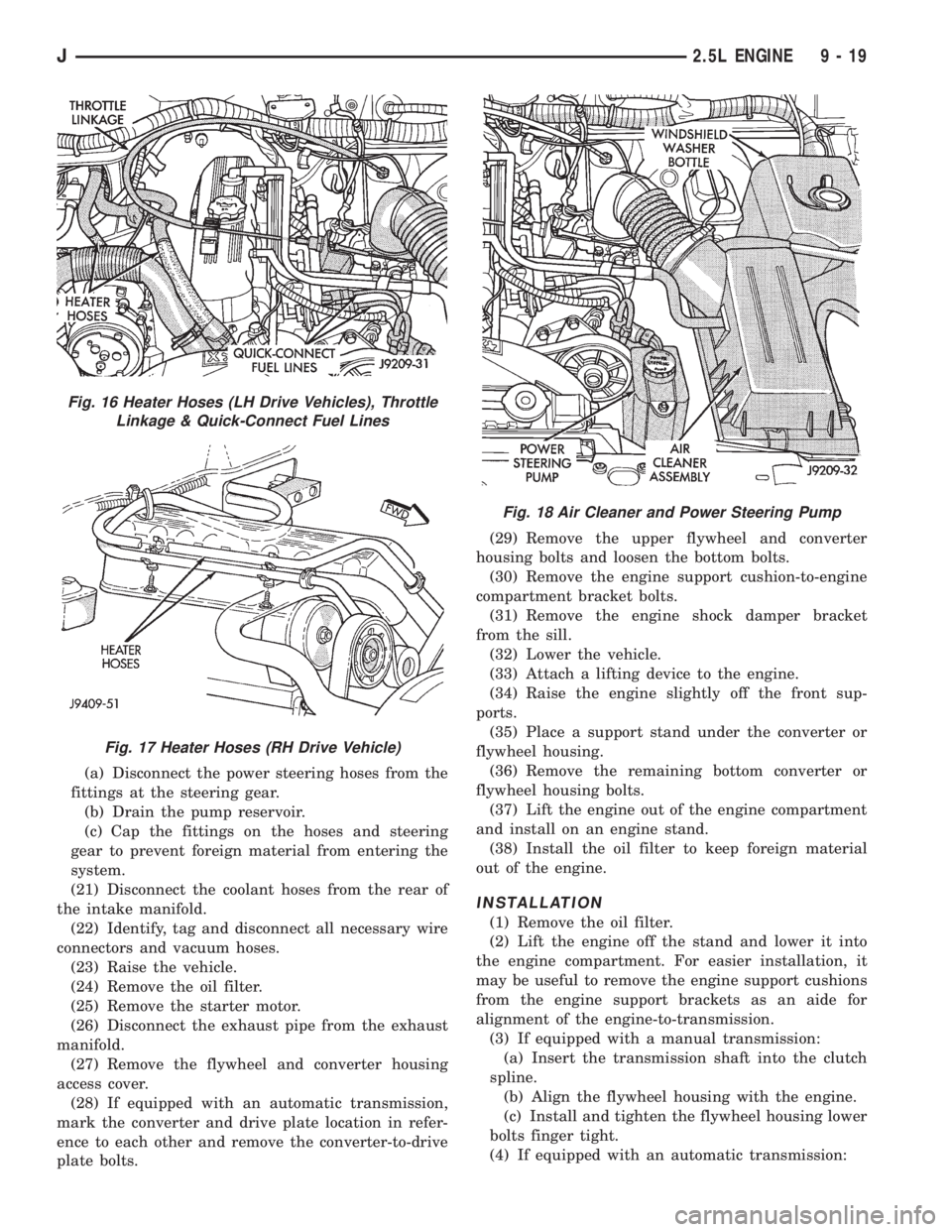
Fig. 16 Heater Hoses (LH Drive Vehicles), Throttle
Linkage & Quick-Connect Fuel Lines
Fig. 17 Heater Hoses (RH Drive Vehicle)
Fig. 18 Air Cleaner and Power Steering Pump
J2.5L ENGINE 9 - 19
Page 1299 of 2158
(a) Align the transmission torque converter hous-
ing with the engine.
(b) Loosely install the converter housing lower
bolts and install the next higher bolt and nut on
each side.
(c) Tighten all 4 bolts finger-tight.
(5) Install the engine support cushions (if re-
moved).
(6) Lower the engine and engine support cushions
onto the engine compartment brackets.
(7) Remove the engine lifting device.
(8) Raise the vehicle.
(9) If equipped with an automatic transmission:
(a) Install the converter-to-drive plate bolts. En-
sure the installation reference marks are aligned.
Tighten the bolts to 54 Nzm (40 ft. lbs.) torque.
(b) Install the converter-housing access cover.
(c) Install the exhaust pipe support.
(10) Install the remaining converter or flywheel
housing bolts.
(11) Install the starter motor and connect the ca-
ble. Tighten the bolts to 45 Nzm (33 ft. lbs.) torque.
(12) Tighten the engine support cushing through-
bolt nuts.
(13) Install the remaining flywheel and converter
housing bolts. Tighten the bolts to 38 Nzm (28 ft. lbs.)
torque.
(14) Connect the exhaust pipe to the manifold.
(15) Install the oil filter.
(16) Lower the vehicle.
(17) Connect the coolant hoses and tighten the
clamps.
(18) If equipped with power steering:
(a) Remove the protective caps
(b) Connect the hoses to the fittings at the steer-
ing gear. Tighten the nut to 52 Nzm (38 ft. lbs.)
torque.
(c) Fill the pump reservoir with fluid.
(19) Remove the pulley-to-water pump flange
alignment capscrew and install the fan and spacer or
Tempatrol fan assembly.
(20) Install the fan shroud and radiator and con-
denser (if equipped with air conditioning).
(21) Connect the radiator hoses.
(22) Connect the automatic transmission fluid
cooler pipes, if equipped.
(23) Connect the oxygen sensor wire connector.
(24) Connect the throttle valve rod and retainer.
Connect the throttle cable and install the rod. Install
the throttle valve rod spring.
(25) Connect the speed control cable, if equipped.
(26) Connect the fuel supply and return lines to
the throttle body.
(27) Connect all the vacuum hoses and wire con-
nectors.
(28) Connect the service valves to the A/C compres-
sor ports, if equipped with air conditioning.(29) Fill the power steering reservoir.
(30) Connect the battery cables.
(31) Install the hood.
(32) Install the air cleaner.
(33) Start the engine and inspect for leaks.
(34) Fill the cooling system.
(35) Stop the engine and check the fluid levels.
Add fluid, as required.
ENGINE ASSEMBLYÐYJ VEHICLES
REMOVAL
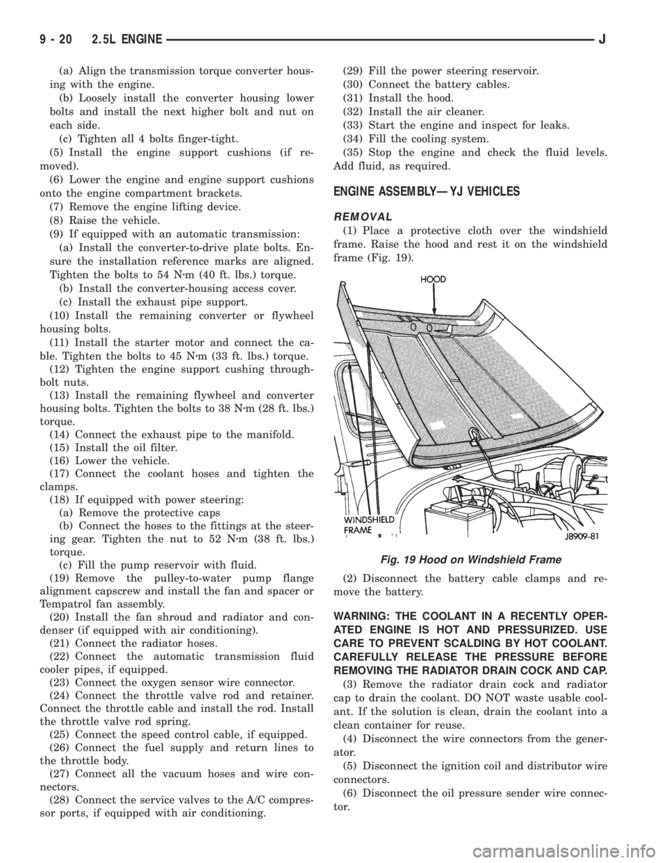
(1) Place a protective cloth over the windshield
frame. Raise the hood and rest it on the windshield
frame (Fig. 19).
(2) Disconnect the battery cable clamps and re-
move the battery.
WARNING: THE COOLANT IN A RECENTLY OPER-
ATED ENGINE IS HOT AND PRESSURIZED. USE
CARE TO PREVENT SCALDING BY HOT COOLANT.
CAREFULLY RELEASE THE PRESSURE BEFORE
REMOVING THE RADIATOR DRAIN COCK AND CAP.
(3) Remove the radiator drain cock and radiator
cap to drain the coolant. DO NOT waste usable cool-
ant. If the solution is clean, drain the coolant into a
clean container for reuse.
(4) Disconnect the wire connectors from the gener-
ator.
(5) Disconnect the ignition coil and distributor wire
connectors.
(6) Disconnect the oil pressure sender wire connec-
tor.
Fig. 19 Hood on Windshield Frame
9 - 20 2.5L ENGINEJ