1995 JEEP XJ INDEX
[x] Cancel search: INDEXPage 232 of 2158
CLUTCH SERVICE
INDEX
page page
Clutch Component Lubrication................ 10
Clutch Cover and Disc Installation............. 10
Clutch Cover and Disc Removal.............. 10
Clutch Fluid Level......................... 14
Clutch Housing Replacement................ 13
Clutch Hydraulic Linkage Installation........... 14
Clutch Hydraulic Linkage Removal............. 13Clutch Pedal Installation.................... 15
Clutch Pedal Removal...................... 15
Clutch Safety Precautions................... 10
Flywheel Service.......................... 16
Pilot Bearing Replacement.................. 12
Release Bearing Replacement................ 11
CLUTCH SAFETY PRECAUTIONS
WARNING: EXERCISE CARE WHEN SERVICING
CLUTCH COMPONENTS. DUST AND DIRT ON
CLUTCH PARTS USE MAY CONTAIN ASBESTOS FI-
BERS. BREATHING EXCESSIVE CONCENTRATIONS
OF THESE FIBERS CAN CAUSE SERIOUS BODILY
HARM. WEAR A RESPIRATOR DURING SERVICE
AND NEVER CLEAN CLUTCH COMPONENTS WITH
COMPRESSED AIR OR WITH A DRY BRUSH. EI-
THER CLEAN THE COMPONENTS WITH A WATER
DAMPENED RAGS OR USE A VACUUM CLEANER
SPECIFICALLY DESIGNED FOR REMOVING ASBES-
TOS FIBERS AND DUST. DO NOT CREATE DUST BY
SANDING A CLUTCH DISC. REPLACE THE DISC IF
THE FRICTION MATERIAL IS DAMAGED OR CON-
TAMINATED. DISPOSE OF ALL DUST AND DIRT
CONTAINING ASBESTOS FIBERS IN SEALED BAGS
OR CONTAINERS. THIS WILL HELP MINIMIZE EX-
POSURE TO YOURSELF AND TO OTHERS. FOL-
LOW ALL RECOMMENDED SAFETY PRACTICES
PRESCRIBED BY THE OCCUPATIONAL SAFETY
AND HEALTH ADMINISTRATION (OSHA) AND THE
ENVIRONMENTAL SAFETY AGENCY (EPA), FOR
THE HANDLING AND DISPOSAL OF PRODUCTS
CONTAINING ASBESTOS.
CLUTCH COMPONENT LUBRICATION
Proper clutch component lubrication is important
to satisfactory operation. Using the correct lubricant
and not overlubricating are equally important. Apply
recommended lubricant sparingly to avoid disc and
pressure plate contamination.
Clutch and transmission components requiring lu-
brication are:
²pilot bearing
²release lever pivot ball stud
²release lever contact surfaces
²release bearing bore
²clutch disc hub splines
²clutch pedal pivot shaft bore
²clutch pedal bushings²input shaft splines
²input shaft pilot hub
²transmission front bearing retainer slide surface
Never apply grease to any part of the clutch
cover, or disc.
Recommended Lubricants
Use Mopar multi-purpose grease for the clutch
pedal bushings and pivot shaft. Use Mopar high tem-
perature grease (or equivalent) for all other lubrica-
tion requirements. Apply recommended amounts and
do not overlubricate.
CLUTCH COVER AND DISC REMOVAL
(1) Remove transmission. Refer to procedures in
Group 21.
(2) If original clutch cover will be reinstalled, mark
position of cover on flywheel for assembly reference.
Use paint or a scriber for this purpose.
(3) If clutch cover is to be replaced, cover bolts can
be removed in any sequence. However, if original
cover will be reinstalled, loosen cover bolts evenly
and in rotation to relieve spring tension equally. This
is necessary avoid warping cover.
(4) Remove cover bolts and remove cover and disc
(Fig. 2).
CLUTCH COVER AND DISC INSTALLATION
(1) Lightly scuff sand flywheel face with 180 grit
emery cloth. Then clean surface with a wax and
grease remover.
(2) Lubricate pilot bearing with Mopar high tem-
perature bearing grease.
(3) Check runout and free operation of new clutch
disc as follows:
(a) Slide disc onto transmission input shaft
splines. Disc should slide freely on splines.
(b) Leave disc on shaft and check face runout
with dial indicator. Check runout at disc hub and
about 6 mm (1/4 in.) from outer edge of facing.
(c) Face runout should not exceed 0.5 mm (0.020
in.). Obtain another clutch disc if runout exceeds
this limit.
6 - 10 CLUTCH SERVICEJ
Page 243 of 2158
DIAGNOSIS
INDEX
page page
DRB Scan Tool............................ 5
On-Board Diagnostics (OBD).................. 4Preliminary Checks......................... 5
ON-BOARD DIAGNOSTICS (OBD)
FOR CERTAIN COOLING SYSTEM
COMPONENTS
The powertrain control module (PCM) has been
programmed to monitor the certain following cooling
system components:
²If the engine has remained cool for too long a pe-
riod, such as with a stuck open thermostat, a Diag-
nostic Trouble Code (DTC) number 17 can be
observed at the malfunction indicator lamp. This
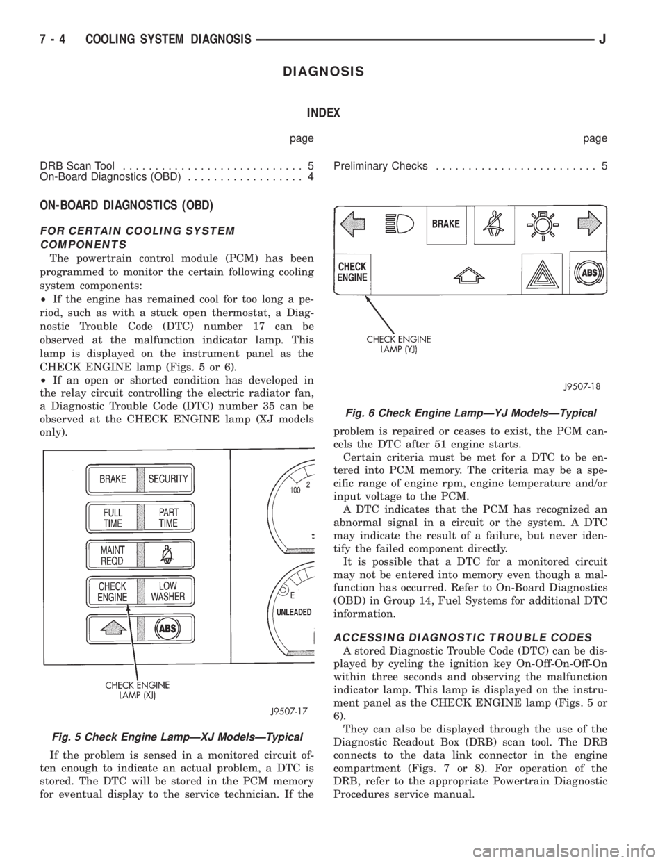
lamp is displayed on the instrument panel as the
CHECK ENGINE lamp (Figs. 5 or 6).
²If an open or shorted condition has developed in
the relay circuit controlling the electric radiator fan,
a Diagnostic Trouble Code (DTC) number 35 can be
observed at the CHECK ENGINE lamp (XJ models
only).
If the problem is sensed in a monitored circuit of-
ten enough to indicate an actual problem, a DTC is
stored. The DTC will be stored in the PCM memory
for eventual display to the service technician. If theproblem is repaired or ceases to exist, the PCM can-
cels the DTC after 51 engine starts.
Certain criteria must be met for a DTC to be en-
tered into PCM memory. The criteria may be a spe-
cific range of engine rpm, engine temperature and/or
input voltage to the PCM.
A DTC indicates that the PCM has recognized an
abnormal signal in a circuit or the system. A DTC
may indicate the result of a failure, but never iden-
tify the failed component directly.
It is possible that a DTC for a monitored circuit
may not be entered into memory even though a mal-
function has occurred. Refer to On-Board Diagnostics
(OBD) in Group 14, Fuel Systems for additional DTC
information.
ACCESSING DIAGNOSTIC TROUBLE CODES
A stored Diagnostic Trouble Code (DTC) can be dis-
played by cycling the ignition key On-Off-On-Off-On
within three seconds and observing the malfunction
indicator lamp. This lamp is displayed on the instru-
ment panel as the CHECK ENGINE lamp (Figs. 5 or
6).
They can also be displayed through the use of the
Diagnostic Readout Box (DRB) scan tool. The DRB
connects to the data link connector in the engine
compartment (Figs. 7 or 8). For operation of the
DRB, refer to the appropriate Powertrain Diagnostic
Procedures service manual.
Fig. 5 Check Engine LampÐXJ ModelsÐTypical
Fig. 6 Check Engine LampÐYJ ModelsÐTypical
7 - 4 COOLING SYSTEM DIAGNOSISJ
Page 252 of 2158
SERVICE PROCEDURES
INDEX
page page
Auxiliary Electric Cooling FanÐXJ Models with 4.0L
6-Cylinder Engine....................... 35
Coolant................................. 20
Coolant Reserve/Overflow System............. 24
Cooling System Cleaning/Reverse Flushing...... 22
Cooling System Fans...................... 32
Cooling System Hoses..................... 32
Draining Cooling System.................... 21
Radiator Pressure Cap..................... 25
Radiators............................... 26Refilling Cooling System.................... 21
Testing Cooling System for Leaks............. 22
Thermostat.............................. 17
Transmission Oil Coolers.................... 36
Viscous Fan Drive......................... 34
Water Pump Tests......................... 13
Water PumpsÐGeneral Information............ 13
Water PumpsÐRemoval/Installation........... 14
WATER PUMPSÐGENERAL INFORMATION
A centrifugal water pump circulates coolant
through the water jackets, passages, intake manifold,
radiator core, cooling system hoses and heater core.
The pump is driven from the engine crankshaft by a
drive belt on all engines.
The water pump impeller is pressed onto the rear
of a shaft that rotates in bearings pressed into the
housing. The housing has a small hole to allow seep-
age to escape. The water pump seals are lubricated
by the antifreeze in the coolant mixture. No addi-
tional lubrication is necessary.
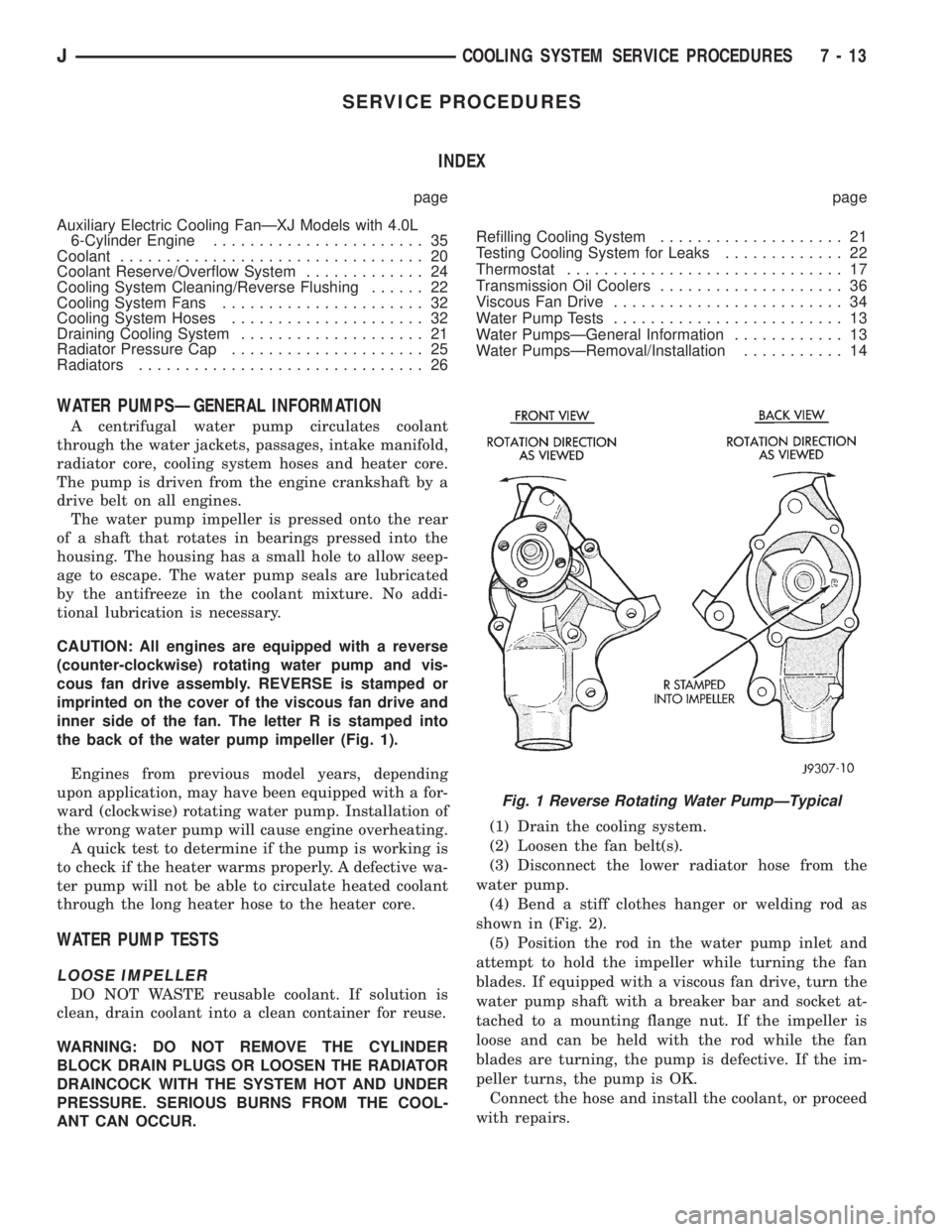
CAUTION: All engines are equipped with a reverse
(counter-clockwise) rotating water pump and vis-
cous fan drive assembly. REVERSE is stamped or
imprinted on the cover of the viscous fan drive and
inner side of the fan. The letter R is stamped into
the back of the water pump impeller (Fig. 1).
Engines from previous model years, depending
upon application, may have been equipped with a for-
ward (clockwise) rotating water pump. Installation of
the wrong water pump will cause engine overheating.
A quick test to determine if the pump is working is
to check if the heater warms properly. A defective wa-
ter pump will not be able to circulate heated coolant
through the long heater hose to the heater core.
WATER PUMP TESTS
LOOSE IMPELLER
DO NOT WASTE reusable coolant. If solution is
clean, drain coolant into a clean container for reuse.
WARNING: DO NOT REMOVE THE CYLINDER
BLOCK DRAIN PLUGS OR LOOSEN THE RADIATOR
DRAINCOCK WITH THE SYSTEM HOT AND UNDER
PRESSURE. SERIOUS BURNS FROM THE COOL-
ANT CAN OCCUR.(1) Drain the cooling system.
(2) Loosen the fan belt(s).
(3) Disconnect the lower radiator hose from the
water pump.
(4) Bend a stiff clothes hanger or welding rod as
shown in (Fig. 2).
(5) Position the rod in the water pump inlet and
attempt to hold the impeller while turning the fan
blades. If equipped with a viscous fan drive, turn the
water pump shaft with a breaker bar and socket at-
tached to a mounting flange nut. If the impeller is
loose and can be held with the rod while the fan
blades are turning, the pump is defective. If the im-
peller turns, the pump is OK.
Connect the hose and install the coolant, or proceed
with repairs.
Fig. 1 Reverse Rotating Water PumpÐTypical
JCOOLING SYSTEM SERVICE PROCEDURES 7 - 13
Page 277 of 2158
ENGINE ACCESSORY DRIVE BELTS
INDEX
page page
Automatic Belt TensionerÐXJ Models with Right
Hand Drive............................ 42
Belt Diagnosis............................ 38
Belt Schematics.......................... 38
Belt ServiceÐExcept Right Hand Drive......... 40
Belt ServiceÐXJ Models with Right Hand Drive . . . 42Belt Tension Specifications.................. 38
Belt TensionÐExcept Right Hand Drive (RHD).... 38
Belt TensionÐRight Hand Drive (RHD)......... 38
General Information....................... 38
GENERAL INFORMATION
CAUTION: When installing a serpentine accessory
drive belt, the belt MUST be routed correctly. If not,
the engine may overheat due to water pump rotat-
ing in wrong direction. Refer to the appropriate en-
gine Belt Schematic in this group for the correct
belt routing. Or, refer to the Belt Routing Label lo-
cated in the engine compartment.
BELT DIAGNOSIS
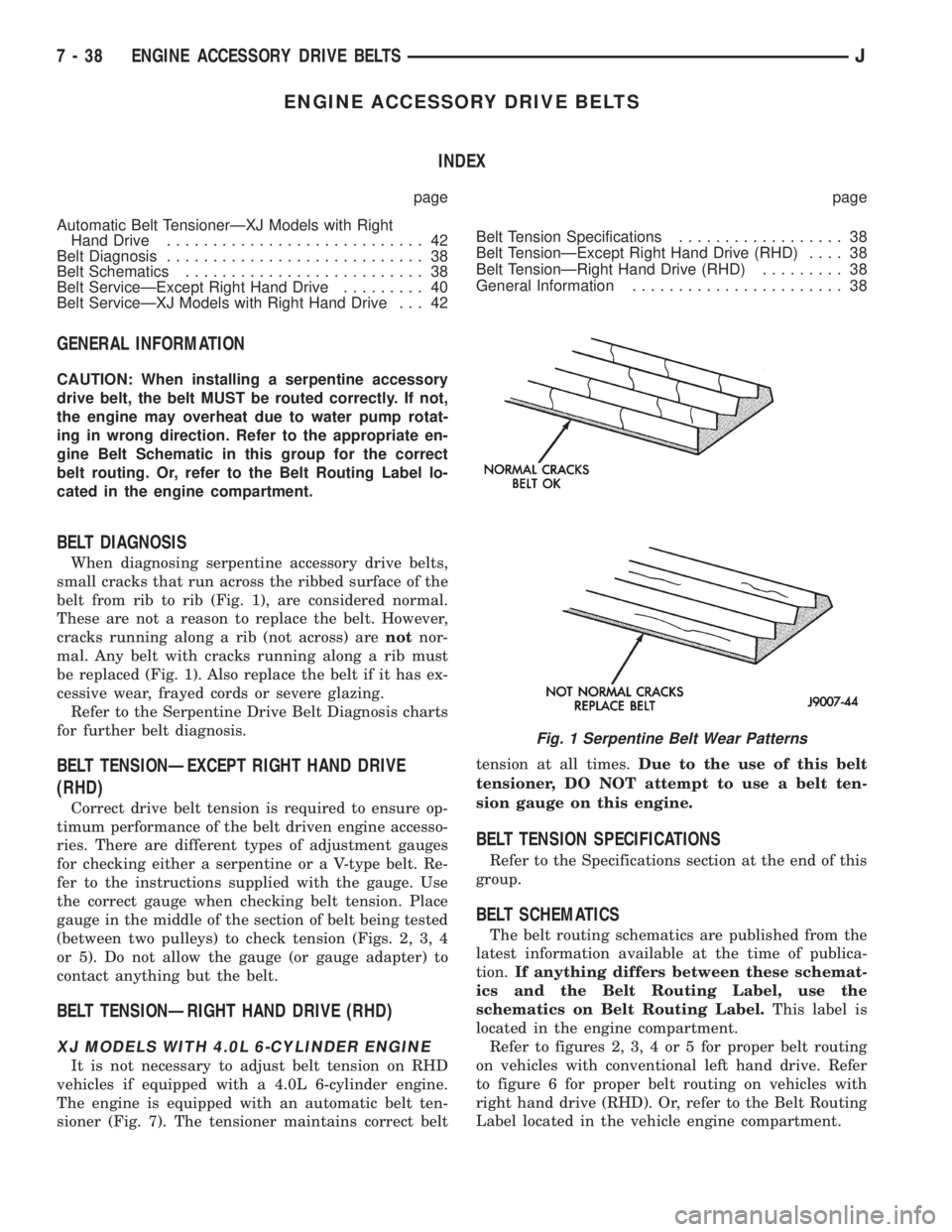
When diagnosing serpentine accessory drive belts,
small cracks that run across the ribbed surface of the
belt from rib to rib (Fig. 1), are considered normal.
These are not a reason to replace the belt. However,
cracks running along a rib (not across) arenotnor-
mal. Any belt with cracks running along a rib must
be replaced (Fig. 1). Also replace the belt if it has ex-
cessive wear, frayed cords or severe glazing.
Refer to the Serpentine Drive Belt Diagnosis charts
for further belt diagnosis.
BELT TENSIONÐEXCEPT RIGHT HAND DRIVE
(RHD)
Correct drive belt tension is required to ensure op-
timum performance of the belt driven engine accesso-
ries. There are different types of adjustment gauges
for checking either a serpentine or a V-type belt. Re-
fer to the instructions supplied with the gauge. Use
the correct gauge when checking belt tension. Place
gauge in the middle of the section of belt being tested
(between two pulleys) to check tension (Figs. 2, 3, 4
or 5). Do not allow the gauge (or gauge adapter) to
contact anything but the belt.
BELT TENSIONÐRIGHT HAND DRIVE (RHD)
XJ MODELS WITH 4.0L 6-CYLINDER ENGINE
It is not necessary to adjust belt tension on RHD
vehicles if equipped with a 4.0L 6-cylinder engine.
The engine is equipped with an automatic belt ten-
sioner (Fig. 7). The tensioner maintains correct belttension at all times.Due to the use of this belt
tensioner, DO NOT attempt to use a belt ten-
sion gauge on this engine.
BELT TENSION SPECIFICATIONS
Refer to the Specifications section at the end of this
group.
BELT SCHEMATICS
The belt routing schematics are published from the
latest information available at the time of publica-
tion.If anything differs between these schemat-
ics and the Belt Routing Label, use the
schematics on Belt Routing Label.This label is
located in the engine compartment.
Refer to figures 2, 3, 4 or 5 for proper belt routing
on vehicles with conventional left hand drive. Refer
to figure 6 for proper belt routing on vehicles with
right hand drive (RHD). Or, refer to the Belt Routing
Label located in the vehicle engine compartment.
Fig. 1 Serpentine Belt Wear Patterns
7 - 38 ENGINE ACCESSORY DRIVE BELTSJ
Page 286 of 2158
ELECTRICAL
GROUP INDEX
Group Group
AUDIO SYSTEMS........................ 8F
BATTERY/STARTER/GENERATOR SERVICE.... 8B
BATTERY/STARTING/CHARGING SYSTEMS
DIAGNOSTICS......................... 8A
CHIME/BUZZER WARNING SYSTEMS........ 8U
HORNS................................ 8G
IGNITION SYSTEMS...................... 8D
INSTRUMENT PANEL AND GAUGES......... 8E
LAMPS................................ 8L
OVERHEAD CONSOLE.................... 8C
POWER LOCKS.......................... 8P
POWER MIRRORS....................... 8TPOWER SEATS.......................... 8R
POWER WINDOWS....................... 8S
REAR WINDOW DEFOGGER............... 8N
RESTRAINT SYSTEMS................... 8M
TURN SIGNAL AND HAZARD WARNING
SYSTEMS............................. 8J
VEHICLE SPEED CONTROL SYSTEM......... 8H
WIPER AND WASHER SYSTEMS............ 8K
XJ WIRING DIAGRAMS-LEFT HAND DRIVE . . . 8W
XJ WIRING DIAGRAMS-RIGHT HAND DRIVE . 8W
YJ WIRING DIAGRAMS.................. 8W
BATTERY/STARTING/CHARGING SYSTEMS DIAGNOSTICS
CONTENTS
page page
BATTERY............................... 2
CHARGING SYSTEM..................... 17
IGNITION-OFF DRAW.................... 10SPECIFICATIONS........................ 23
STARTING SYSTEM...................... 11
USING ON-BOARD DIAGNOSTIC SYSTEM.... 22
GENERAL INFORMATION
The battery, starting, and charging systems operate
with one another; therefore, they must be tested as a
complete system. In order for the vehicle to start and
charge properly, all of the components involved in
these systems must perform within specifications.
Group 8A covers battery, starting (Fig. 1) and
charging (Fig. 2) system diagnostic procedures. These
procedures include the most basic conventional diag-
nostic methods, to On-Board Diagnostics (OBD) builtinto the Powertrain Control Module (PCM). Use of an
induction milliamp ammeter, volt/ohmmeter, battery
charger, carbon pile rheostat (load tester), and 12-
volt test lamp will be required.
All OBD-sensed systems are monitored by the
PCM. Each monitored circuit is assigned a Diagnos-
tic Trouble Code (DTC). The PCM will store a DTC in
electronic memory for any failure it detects. See Us-
ing On-Board Diagnostic System in this group for
more information.
JELECTRICAL 8A - 1
Page 325 of 2158

IGNITION SYSTEMS
CONTENTS
page page
COMPONENT IDENTIFICATION/SYSTEM
OPERATION........................... 1
COMPONENT REMOVAL/INSTALLATION...... 17
DIAGNOSTICS/SERVICE PROCEDURES....... 6IGNITION SWITCHÐXJ MODELS........... 26
IGNITION SWITCHÐYJ MODELS........... 29
SPECIFICATIONS........................ 32
COMPONENT IDENTIFICATION/SYSTEM OPERATION
INDEX
page page
Automatic Shutdown (ASD) Relay.............. 1
Camshaft Position Sensor.................... 2
Crankshaft Position Sensor................... 3
Distributors............................... 4
Engine Coolant Temperature Sensor............ 5
General Information........................ 1Ignition Coil.............................. 4
Intake Manifold Air Temperature Sensor.......... 5
Manifold Absolute Pressure (MAP) Sensor........ 5
Oxygen (O2S) Sensor....................... 5
Powertrain Control Module (PCM).............. 5
Throttle Position Sensor..................... 5
GENERAL INFORMATION
Throughout this group, references are made to par-
ticular vehicle models by alphabetical designation
(XJ or YJ) or by the particular vehicle nameplate. A
chart showing a breakdown of alphabetical designa-
tions is included in the Introduction group at the be-
ginning of this manual.
This section of the group, Component Identifica-
tion/System Operation, will discuss ignition system
operation and will identify ignition system compo-
nents.
For diagnostic procedures and adjustments, refer to
the Diagnostics/Service Procedures section of this
group.
For removal and installation of ignition system
components, refer to the Component Removal/Instal-
lation section of this group.
For other useful information, refer to On-Board Di-
agnostics in the General Diagnosis sections of Group
14, Fuel System in this manual.
For operation of the DRB Scan Tool, refer to the
appropriate Powertrain Diagnostic Procedures ser-
vice manual.
An Ignition specifications section is included at the
end of this group. A general Maintenance Schedule
(mileage intervals) for ignition related items can be
found in Group 0, Lubrication and Maintenance. This
schedule can also be found in the Owners Manual.
IGNITION SYSTEMS
A multi-port, fuel injected engine is used on all
models. The ignition system is controlled by the pow-
ertrain control module (PCM) on all engines. The
PCM was formerly referred to as the SBEC or engine
controller.
The ignition system consists of:
²Spark plugs
²Ignition coil
²Secondary ignition cables
²Distributor (contains rotor and camshaft position
sensor)
²Powertrain control module (PCM)
²Crankshaft position sensor
AUTOMATIC SHUTDOWN (ASD) RELAY
The automatic shutdown (ASD) relay is located in
the power distribution center (PDC) near the battery
(Fig. 1 or 2). As one of its functions, it will supply
battery voltage to the ignition coil.
The ground circuit for the ASD relay is controlled
by the powertrain control module (PCM). This is
done through pin/cavity number 51 of the PCM 60-
way connector. The PCM then regulates ASD relay
operation by switching this ground circuit on-and-off.
Also refer to Ignition Coil for additional informa-
tion.
JIGNITION SYSTEMS 8D - 1
Page 330 of 2158

DIAGNOSTICS/SERVICE PROCEDURES
INDEX
page page
Automatic Shutdown (ASD) Relay Test.......... 6
Camshaft Position Sensor Test................ 6
Crankshaft Position Sensor Test............... 7
Distributor Cap............................ 7
Distributor Rotor........................... 8
DRB Scan Tool............................ 8
Engine Coolant Temperature Sensor Test........ 9
General Information........................ 6
Ignition Coil.............................. 9
Ignition Secondary Circuit Diagnosis........... 10Ignition Timing............................ 11
Intake Manifold Air Temperature Sensor Test..... 11
Manifold Absolute Pressure (MAP) Sensor Test . . . 11
On-Board Diagnostics...................... 15
Oxygen (O2S) Sensor Tests................. 15
Powertrain Control Module (PCM)............. 11
Spark Plug Secondary Cables................ 14
Spark Plugs............................. 12
Throttle Position Sensor Test................. 15
GENERAL INFORMATION
This section of the group, Diagnostics/Service Pro-
cedures, will discuss basic ignition system diagnostics
and service adjustments.
For system operation and component identification,
refer to the Component Identification/System Opera-
tion section of this group.
For removal or installation of ignition system com-
ponents, refer to the Component Removal/Installa-
tion section of this group.
For other useful information, refer to the On-Board
Diagnostics section.
For operation of the DRB Scan Tool, refer to the
appropriate Powertrain Diagnostic Procedures ser-
vice manual.
AUTOMATIC SHUTDOWN (ASD) RELAY TEST
To perform a complete test of this relay and its cir-
cuitry, refer to the DRB scan tool. Also refer to the
appropriate Powertrain Diagnostics Procedures man-
ual. To test the relay only, refer to RelaysÐOpera-
tion/Testing in the Group 14, Fuel Systems section.
CAMSHAFT POSITION SENSOR TEST
To perform a complete test of this sensor and its
circuitry, refer to the DRB scan tool. Also refer to the
appropriate Powertrain Diagnostics Procedures man-
ual. To test the sensor only, refer to the following:
The camshaft position sensor is located in the dis-
tributor (Fig. 1).
To perform a complete test of this sensor and its
circuitry, refer to the DRB scan tool. Also refer to the
appropriate Powertrain Diagnostics Procedures man-
ual. To test the sensor only, refer to the following:
For this test, an analog (non-digital) voltme-
ter is needed.Do not remove the distributor connec-
tor from the distributor. Using small paper clips,
insert them into the backside of the distributor wire
harness connector to make contact with the termi-nals. Be sure that the connector is not damaged
when inserting the paper clips. Attach voltmeter
leads to these paper clips.
(1) Connect the positive (+) voltmeter lead into the
sensor output wire. This is at done the distributor
wire harness connector. For wire identification, refer
to Group 8W, Wiring Diagrams.
(2) Connect the negative (-) voltmeter lead into the
ground wire. For wire identification, refer to Group
8W, Wiring Diagrams.
(3) Set the voltmeter to the 15 Volt DC scale.
(4) Remove distributor cap from distributor (two
screws). Rotate (crank) the engine until the distribu-
tor rotor is pointed to approximately the 11 o'clock
position. The movable pulse ring should now be
within the sensor pickup.
(5) Turn ignition key to ON position. The voltmeter
should read approximately 5.0 volts.
(6) If voltage is not present, check the voltmeter
leads for a good connection.
(7) If voltage is still not present, check for voltage
at the supply wire. For wire identification, refer to
Group 8W, Wiring Diagrams.
Fig. 1 Camshaft Position SensorÐTypical
8D - 6 IGNITION SYSTEMSJ
Page 341 of 2158

COMPONENT REMOVAL/INSTALLATION
INDEX
page page
Automatic Shutdown (ASD) Relay............. 17
Camshaft Position Sensor................... 17
Crankshaft Position Sensor.................. 17
Distributor............................... 19
Engine Coolant Temperature Sensor........... 19
General Information....................... 17
Ignition Coil............................. 22Intake Manifold Air Temperature Sensor......... 23
Manifold Absolute Pressure (MAP) Sensor....... 23
Oxygen (O2S) Sensor...................... 23
Powertrain Control Module (PCM)............. 23
Spark Plug Secondary Cables................ 24
Spark Plugs............................. 23
Throttle Position Sensor (TPS)............... 25
GENERAL INFORMATION
This section of the group, Component Removal/In-
stallation, will discuss the removal and installation
of ignition system components.
For basic ignition system diagnostics and service
adjustments, refer to the Diagnostics/Service Proce-
dures section of this group.
For system operation and component identification,
refer to the Component Identification/System Opera-
tion section of this group.
AUTOMATIC SHUTDOWN (ASD) RELAY
The ASD relay is installed in the power distribu-
tion center (PDC) (Figs. 1 or 2). Relay location is
printed on the PDC cover.
REMOVAL
(1) Remove the PDC cover.
(2) Remove the relay by lifting straight up.
INSTALLATION
(1) Check the condition of relay wire terminals at
PDC before installing relay. Repair as necessary.
(2) Push the relay into the connector.
(3) Install the relay cover.
CAMSHAFT POSITION SENSOR
The camshaft position sensor is located in the dis-
tributor (Fig. 3).
REMOVAL
Distributor removal is not necessary to remove
camshaft position sensor.
(1) Disconnect negative battery cable at battery.
(2) Remove distributor cap from distributor (two
screws).
(3) Disconnect camshaft position sensor wiring
harness from main engine wiring harness.
(4) Remove distributor rotor from distributor shaft.
(5) Lift the camshaft position sensor assembly
from the distributor housing (Fig. 3).
INSTALLATION
(1) Install camshaft position sensor to distributor.
Align sensor into notch on distributor housing.
(2) Connect wiring harness.
(3) Install rotor.
(4) Install distributor cap. Tighten mounting
screws.
CRANKSHAFT POSITION SENSOR
The crankshaft position sensor is mounted in the
Fig. 1 PDCÐXJ Models
Fig. 2 PDCÐYJ Models
JIGNITION SYSTEMS 8D - 17