1995 JEEP XJ INDEX
[x] Cancel search: INDEXPage 167 of 2158
MASTER CYLINDERÐCOMBINATION VALVE
INDEX
page page
Combination Valve Replacement (Non-ABS)..... 16
General Service Information................. 15
Master Cylinder and Combination Valve Installation
(With ABS)............................. 20
Master Cylinder and Combination Valve Removal
(With ABS)............................. 17Master Cylinder Bench Bleeding.............. 21
Master Cylinder Installation (Non-ABS)......... 16
Master Cylinder Overhaul (4-Cylinder Models).... 16
Master Cylinder Removal (Non-ABS)........... 15
Reservoir Replacement (2-Piece Master Cylinder) . 19
GENERAL SERVICE INFORMATION
Master Cylinder
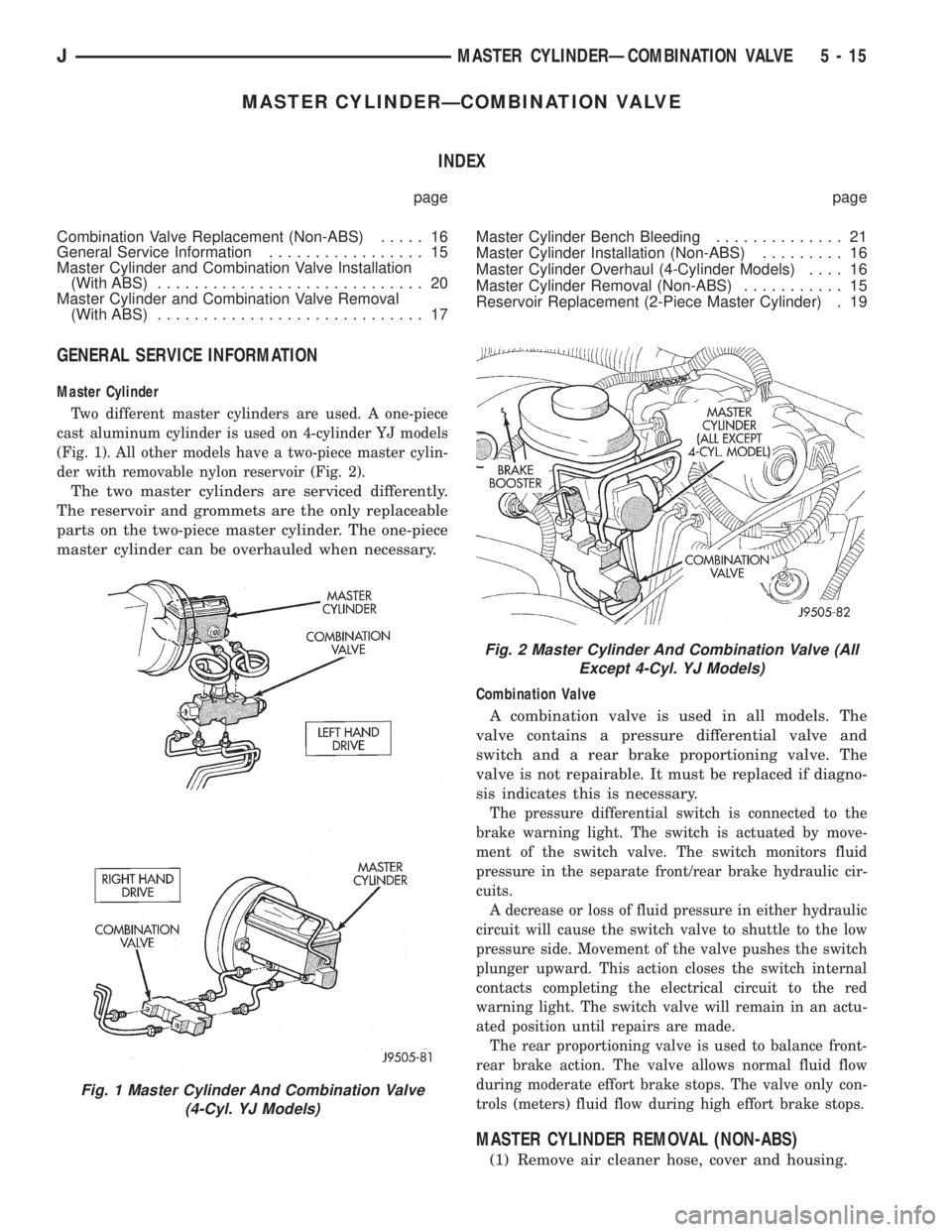
Two different master cylinders are used. A one-piece
cast aluminum cylinder is used on 4-cylinder YJ models
(Fig. 1). All other models have a two-piece master cylin-
der with removable nylon reservoir (Fig. 2).
The two master cylinders are serviced differently.
The reservoir and grommets are the only replaceable
parts on the two-piece master cylinder. The one-piece
master cylinder can be overhauled when necessary.
Combination Valve
A combination valve is used in all models. The
valve contains a pressure differential valve and
switch and a rear brake proportioning valve. The
valve is not repairable. It must be replaced if diagno-
sis indicates this is necessary.
The pressure differential switch is connected to the
brake warning light. The switch is actuated by move-
ment of the switch valve. The switch monitors fluid
pressure in the separate front/rear brake hydraulic cir-
cuits.
A decrease or loss of fluid pressure in either hydraulic
circuit will cause the switch valve to shuttle to the low
pressure side. Movement of the valve pushes the switch
plunger upward. This action closes the switch internal
contacts completing the electrical circuit to the red
warning light. The switch valve will remain in an actu-
ated position until repairs are made.
The rear proportioning valve is used to balance front-
rear brake action. The valve allows normal fluid flow
during moderate effort brake stops. The valve only con-
trols (meters) fluid flow during high effort brake stops.
MASTER CYLINDER REMOVAL (NON-ABS)
(1) Remove air cleaner hose, cover and housing.
Fig. 1 Master Cylinder And Combination Valve
(4-Cyl. YJ Models)
Fig. 2 Master Cylinder And Combination Valve (All
Except 4-Cyl. YJ Models)
JMASTER CYLINDERÐCOMBINATION VALVE 5 - 15
Page 174 of 2158
POWER BRAKE BOOSTERÐBRAKE PEDALÐBRAKELIGHT SWITCH
INDEX
page page
Brake Pedal Installation..................... 31
Brake Pedal Removal...................... 31
Brakelight Switch Adjustment................. 32
Brakelight Switch Installation................. 32
Brakelight Switch Removal.................. 32
General Information....................... 22
Power Brake Booster Installation (XJ with ABS) . . . 27
Power Brake Booster Installation (XJ Without ABS).. 30
Power Brake Booster Installation (YJ).......... 30
Power Brake Booster Operation.............. 23
Power Brake Booster Removal (XJ with ABS).... 24
Power Brake Booster Removal (XJ Without ABS) . . 29
Power Brake Booster Removal (YJ)............ 30
GENERAL INFORMATION
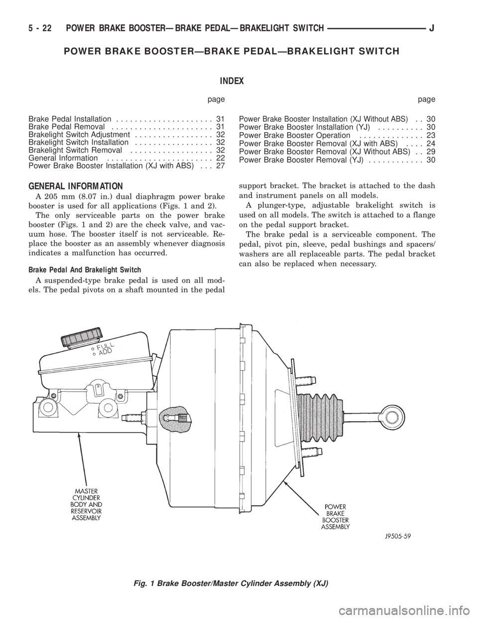
A 205 mm (8.07 in.) dual diaphragm power brake
booster is used for all applications (Figs. 1 and 2).
The only serviceable parts on the power brake
booster (Figs. 1 and 2) are the check valve, and vac-
uum hose. The booster itself is not serviceable. Re-
place the booster as an assembly whenever diagnosis
indicates a malfunction has occurred.
Brake Pedal And Brakelight Switch
A suspended-type brake pedal is used on all mod-
els. The pedal pivots on a shaft mounted in the pedalsupport bracket. The bracket is attached to the dash
and instrument panels on all models.
A plunger-type, adjustable brakelight switch is
used on all models. The switch is attached to a flange
on the pedal support bracket.
The brake pedal is a serviceable component. The
pedal, pivot pin, sleeve, pedal bushings and spacers/
washers are all replaceable parts. The pedal bracket
can also be replaced when necessary.
Fig. 1 Brake Booster/Master Cylinder Assembly (XJ)
5 - 22 POWER BRAKE BOOSTERÐBRAKE PEDALÐBRAKELIGHT SWITCHJ
Page 185 of 2158

ABS OPERATION AND SERVICE
INDEX
page page
ABS Component Serviceability............... 37
ABS Diagnostic Connector.................. 35
ABS Operation in Antilock Braking Mode........ 36
ABS Operation in Normal Braking Mode........ 35
ABS System Power-Up and Initialization........ 35
Acceleration Switch........................ 35
Acceleration Switch Installation............... 39
Acceleration Switch Operation................ 37
Acceleration Switch Removal................ 39
Combination Valve........................ 34
ECU Installation (XJ Models)................. 40
ECU Operation........................... 37
ECU Removal (XJ Models).................. 40
ECU Removal/Installation (YJ Models).......... 41
Electronic Control Unit (ECU)................ 34
Front Wheel Sensor Installation............... 38
Front Wheel Sensor Removal................ 38HCU Installation (XJ)....................... 43
HCU Installation (YJ)....................... 44
HCU Operation........................... 36
HCU Removal (XJ)........................ 41
HCU Removal (YJ)........................ 44
Hydraulic Control Unit (HCU)................. 33
Ignition Switch........................... 35
Master Cylinder/Power Brake Booster.......... 34
Rear Wheel Sensor Installation and Adjustment . . . 38
Rear Wheel Sensor Removal................ 38
Speed Sensor Air Gap..................... 37
System Description........................ 33
System Relays........................... 35
System Warning Light...................... 35
Wheel Speed Sensor Operation.............. 37
Wheel Speed Sensors..................... 34
SYSTEM DESCRIPTION
The Jeep antilock brake system (ABS) is an elec-
tronically operated, all wheel brake control system.
The system is designed to prevent wheel lockup
and maintain steering control during periods of high
wheel slip when braking. Preventing lockup is accom-
plished by modulating fluid pressure to the wheel
brake units.
The hydraulic system is a three channel design.
The front wheel brakes are controlled individually
and the rear wheel brakes in tandem (Fig. 1). The
ABS electrical system is separate from other electri-
cal circuits in the vehicle. A specially programmed
electronic control unit (ECU) operates the system
components.
ABS system major components include:
²hydraulic control unit (HCU)
²electronic control unit (ECU)
²wheel speed sensors and axle shaft tone rings
²acceleration switch
²main relay and pump motor relay
²ABS warning light
²pump motor sensor
HYDRAULIC CONTROL UNIT (HCU)
The hydraulic control unit (HCU) consists of a
valve body, pump body, accumulators, pump motor,
and wire harnesses (Fig. 2).
The pump, motor, and accumulators are combined
into an assembly attached to the valve body. The ac-
cumulators store the extra fluid released to the sys-
tem for ABS mode operation. The pump provides the
fluid volume needed and is operated by a DC type
motor. The motor is controlled by the ECU.The valve body contains the solenoid valves. The
valves modulate brake pressure during antilock brak-
ing and are controlled by the ECU.
The HCU provides three channel pressure control
to the front and rear brakes. One channel controls
the rear wheel brakes in tandem. The two remaining
channels control the front wheel brakes individually.
During antilock braking, the solenoid valves are
opened and closed as needed. The valves are not static.
They are cycled rapidly and continuously to modulate
pressure and control wheel slip and deceleration.
Fig. 1 Jeep ABS System
JABS OPERATION AND SERVICE 5 - 33
Page 197 of 2158
DISC BRAKES
INDEX
page page
Caliper Assembly......................... 50
Caliper Cleaning and Inspection.............. 50
Caliper Disassembly....................... 48
Caliper Installation........................ 51
Caliper Operation and Wear Compensation...... 45
Caliper Removal.......................... 48
Disc Brake Rotor Refinishing................. 53
Disc Brake Rotor Runout.................... 52Disc Brake Rotor Thickness................. 52
Disc Brake Rotor Thickness Variation.......... 52
Disc Brakeshoe Installation.................. 47
Disc Brakeshoe Removal................... 46
General Information....................... 45
Rotor Installation.......................... 51
Rotor Removal........................... 51
Wheel Nut Tightening...................... 54
GENERAL INFORMATION
Jeep XJ/YJ models are equipped with single piston,
floating-type disc brake calipers. Ventilated, cast ro-
tors are used for all applications.
The disc brake calipers are supported in mounting
arms that are an integral part of the steering
knuckle. The calipers slide on mounting bolts that
also attach the calipers to the steering knuckle.
CALIPER OPERATION AND WEAR COMPENSATION
Caliper Operation
The significant feature of single piston caliper op-
eration is that the calipers are free to slide laterally
on the mounting bolts. It is the freedom of lateral
movement that allows continuous compensation for
lining wear.
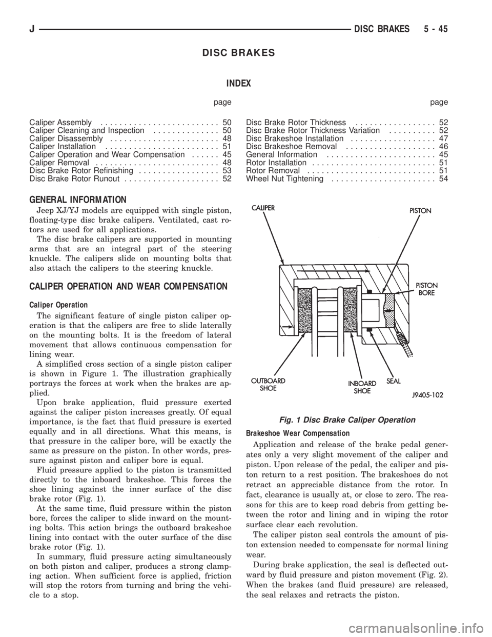
A simplified cross section of a single piston caliper
is shown in Figure 1. The illustration graphically
portrays the forces at work when the brakes are ap-
plied.
Upon brake application, fluid pressure exerted
against the caliper piston increases greatly. Of equal
importance, is the fact that fluid pressure is exerted
equally and in all directions. What this means, is
that pressure in the caliper bore, will be exactly the
same as pressure on the piston. In other words, pres-
sure against piston and caliper bore is equal.
Fluid pressure applied to the piston is transmitted
directly to the inboard brakeshoe. This forces the
shoe lining against the inner surface of the disc
brake rotor (Fig. 1).
At the same time, fluid pressure within the piston
bore, forces the caliper to slide inward on the mount-
ing bolts. This action brings the outboard brakeshoe
lining into contact with the outer surface of the disc
brake rotor (Fig. 1).
In summary, fluid pressure acting simultaneously
on both piston and caliper, produces a strong clamp-
ing action. When sufficient force is applied, friction
will stop the rotors from turning and bring the vehi-
cle to a stop.Brakeshoe Wear Compensation
Application and release of the brake pedal gener-
ates only a very slight movement of the caliper and
piston. Upon release of the pedal, the caliper and pis-
ton return to a rest position. The brakeshoes do not
retract an appreciable distance from the rotor. In
fact, clearance is usually at, or close to zero. The rea-
sons for this are to keep road debris from getting be-
tween the rotor and lining and in wiping the rotor
surface clear each revolution.
The caliper piston seal controls the amount of pis-
ton extension needed to compensate for normal lining
wear.
During brake application, the seal is deflected out-
ward by fluid pressure and piston movement (Fig. 2).
When the brakes (and fluid pressure) are released,
the seal relaxes and retracts the piston.
Fig. 1 Disc Brake Caliper Operation
JDISC BRAKES 5 - 45
Page 207 of 2158
DRUM BRAKES
INDEX
page page
Brake Drum Refinishing.................... 58
Drum Brake Adjustment.................... 57
Drum Brakeshoe Installation................. 55
Drum Brakeshoe Removal................... 55
Support Plate Replacement.................. 58Wheel Cylinder Installation.................. 58
Wheel Cylinder Overhaul.................... 57
Wheel Cylinder Removal.................... 57
Wheel Nut Tightening...................... 59
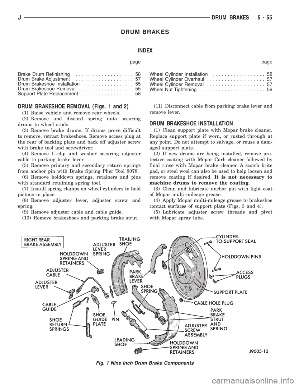
DRUM BRAKESHOE REMOVAL (Figs. 1 and 2)
(1) Raise vehicle and remove rear wheels.
(2) Remove and discard spring nuts securing
drums to wheel studs.
(3) Remove brake drums. If drums prove difficult
to remove, retract brakeshoes. Remove access plug at
the rear of backing plate and back off adjuster screw
with brake tool and screwdriver.
(4) Remove U-clip and washer securing adjuster
cable to parking brake lever.
(5) Remove primary and secondary return springs
from anchor pin with Brake Spring Plier Tool 8078.
(6) Remove holddown springs, retainers and pins
with standard retaining spring tool.
(7) Install spring clamps on wheel cylinders to hold
pistons in place.
(8) Remove adjuster lever, adjuster screw and
spring.
(9) Remove adjuster cable and cable guide.
(10) Remove brakeshoes and parking brake strut.(11) Disconnect cable from parking brake lever and
remove lever.
DRUM BRAKESHOE INSTALLATION
(1) Clean support plate with Mopar brake cleaner.
Replace support plate if worn, or rusted through at
any point. Do not attempt to salvage, or reuse a dam-
aged support plate.
(2) If new drums are being installed, remove pro-
tective coating with Mopar Carb cleaner followed by
final rinse with Mopar brake cleaner. A scotch brite
pad, or steel wool can also be used to help loosen and
remove coating if desired.It is not necessary to
machine drums to remove the coating.
(3) Clean and lubricate anchor pin with light coat
of Mopar multi-mileage grease.
(4) Apply Mopar multi-mileage grease to brakeshoe
contact surfaces of support plate (Figs. 3 and 4).
(5) Lubricate adjuster screw threads and pivot
with Mopar spray lube.
Fig. 1 Nine Inch Drum Brake Components
JDRUM BRAKES 5 - 55
Page 212 of 2158
PARKING BRAKES
INDEX
page page
General Service Information................. 60
Parking Brake Cable Tensioner Adjustment (XJ/YJ).. 68
Parking Brake Cable Tensioner Replacement (XJ) . 65
Parking Brake Front Cable Replacement (YJ).... 67
Parking Brake Lever Installation (XJ with Full
Console).............................. 64
Parking Brake Lever Installation (XJ with Mini
Console).............................. 63
Parking Brake Lever Installation (XJ Without
Console).............................. 65Parking Brake Lever Removal (XJ with Full Console).63
Parking Brake Lever Removal (XJ with Mini
Console).............................. 62
Parking Brake Lever Removal (XJ Without Console).64
Parking Brake Operation.................... 60
Parking Brake Pedal Installation (YJ)........... 66
Parking Brake Pedal Removal (YJ)............ 66
Parking Brake Rear Cable Replacement (XJ)..... 66
Parking Brake Rear Cable Replacement (YJ)..... 68
Parking Brake Switch...................... 68
GENERAL SERVICE INFORMATION
Parking brake adjustment is controlled by a cable ten-
sioner mechanism.
The cable tensioner, once adjusted at the factory,
should not need further adjustment under normal
circumstances. There are only two instances when
adjustment is required. The first is when a new ten-
sioner, or cables have been installed. And the second,
is when the tensioner and cables are disconnected for
access to other brake components.
PARKING BRAKE OPERATION
The rear brakes are utilized for the parking brake
function. They are actuated hydraulically during nor-
mal brake operation but are mechanically actuated
for parking brake operation.
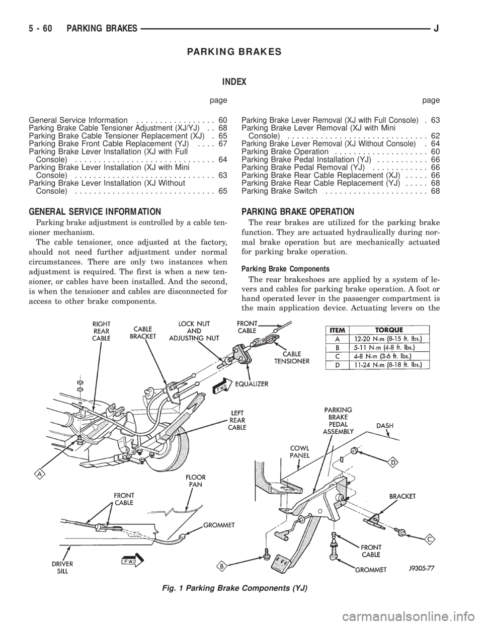
Parking Brake Components
The rear brakeshoes are applied by a system of le-
vers and cables for parking brake operation. A foot or
hand operated lever in the passenger compartment is
the main application device. Actuating levers on the
Fig. 1 Parking Brake Components (YJ)
5 - 60 PARKING BRAKESJ
Page 223 of 2158
CLUTCH
CONTENTS
page page
CLUTCH DIAGNOSIS...................... 3
CLUTCH SERVICE....................... 10GENERAL INFORMATION.................. 1
GENERAL INFORMATION
INDEX
page page
Clutch Components........................ 1
Clutch Linkage Fluid........................ 1Clutch Operation........................... 2
Hydraulic Linkage Components................ 1
CLUTCH COMPONENTS
The clutch mechanism in XJ/YJ models consists of
a single, dry-type disc and a diaphragm style clutch
cover. A hydraulic linkage is used to operate the
clutch release bearing and fork.
A needle-type pilot bearing supports the transmis-
sion input shaft in the crankshaft. A sleeve type re-
lease bearing is used to engage and disengage the
clutch cover pressure plate.
The release bearing is operated by a release fork in
the clutch housing. The fork pivots on a ball stud
mounted in the housing. The release fork is actuated
by a hydraulic slave cylinder mounted in the hous-
ing. The slave cylinder is operated by a clutch master
cylinder mounted on the dash panel. The cylinder
push rod is connected to the clutch pedal.
The clutch disc has cushion springs in the disc hub.
The clutch disc facing is riveted to the hub. The fac-
ing is made from a non-asbestos material. The clutch
cover pressure plate is a diaphragm type with a one-
piece spring and multiple release fingers. The pres-
sure plate release fingers are preset during
manufacture and are not adjustable.
HYDRAULIC LINKAGE COMPONENTS
The hydraulic linkage consists of a clutch master
cylinder with integral reservoir, a clutch slave cylin-
der and an interconnecting fluid line.The clutch master cylinder push rod is connected to
the clutch pedal. The slave cylinder push rod is con-
nected to the clutch release fork. The master cylinder
is mounted on the driver side of the dash panel ad-
jacent to the brake master cylinder and booster as-
sembly. This positioning is similar for both left and
right hand drive models.
CLUTCH LINKAGE FLUID
The integral clutch master cylinder reservoir, slave
cylinder and fluid lines are prefilled with fluid prior
to assembly operations.
The hydraulic system should not require additional
fluid under normal circumstances. In fact,the reser-
voir fluid level will actually increase as normal
clutch wear occurs. For this reason, it is impor-
tant to avoid overfilling, or removing fluid from
the reservoir. This will cause clutch release
problems.
If inspection or diagnosis indicates additional fluid
may be needed, use Mopar brake fluid, or an equiv-
alent meeting standards SAE J1703 and DOT 3. Do
not use any other type of fluid.
JCLUTCH 6 - 1
Page 225 of 2158
CLUTCH DIAGNOSIS
INDEX
page page
Clutch Contamination....................... 3
Clutch Cover and Disc Runout................ 3
Clutch Housing Misalignment................. 4
Clutch Misalignment........................ 3Flywheel Runout........................... 3
General Diagnosis Information................ 3
Inspection and Diagnosis Charts............... 4
Installation Methods and Parts Usage........... 4
GENERAL DIAGNOSIS INFORMATION
Unless the cause of a clutch problem is obvious, ac-
curate problem diagnosis will usually require a road
test to confirm a problem. Component inspection will
then be required to determine the actual problem
cause.
During a road test, drive the vehicle at normal
speeds. Shift the transmission through all gear
ranges and observe clutch action. If chatter, grab,
slip, or improper release is experienced, remove and
inspect the clutch components. However, if the prob-
lem is noise or hard shifting, further diagnosis may
be needed as the transmission or another driveline
component may be at fault. Careful observation dur-
ing the test will help narrow the problem area.
CLUTCH CONTAMINATION
Fluid contamination is a frequent cause of clutch
malfunctions. Oil, water, or clutch fluid on the clutch
disc and pressure plate surfaces will cause chatter,
slip and grab.
During inspection, note if any components are con-
taminated with oil, hydraulic fluid, or water/road
splash.
Oil contamination indicates a leak at either the
rear main seal or transmission input shaft. Oil leak-
age produces a residue of oil on the housing interior
and on the clutch cover and flywheel. Heat buildup
caused by slippage between the cover, disc and fly-
wheel, can sometimes bake the oil residue onto the
components. The glaze-like residue ranges in color
from amber to black.
Road splash contamination means dirt/water is en-
tering the clutch housing due to loose bolts, housing
cracks, or through hydraulic line openings. Driving
through deep water puddles can force water/road
splash into the housing through such openings.
Clutch fluid leaks are usually from damaged slave
cylinder push rod seals. This type of leak can only be
confirmed by visual inspection.
CLUTCH MISALIGNMENT
Clutch components must be in proper alignment
with the crankshaft and transmission input shaft.Misalignment caused by excessive runout or warpage
of any clutch component will cause grab, chatter and
improper clutch release.
FLYWHEEL RUNOUT
Check flywheel runout whenever misalignment is
suspected. Flywheel runout should not exceed 0.08
mm (0.003 in.). Measure runout at the outer edge of
the flywheel face with a dial indicator. Mount the in-
dicator on a stud installed in place of one of the fly-
wheel bolts.
Common causes of runout are:
²heat warpage
²improper machining
²incorrect bolt tightening
²improper seating on crankshaft flange shoulder
²foreign material on crankshaft flange
Flywheel machining is not recommended. The fly-
wheel clutch surface is machined to a unique contour
and machining will negate this feature. However, mi-
nor flywheel scoring can be cleaned up by hand with
180 grit emery, or with surface grinding equipment.
Remove only enough material to reduce scoring (ap-
proximately 0.001 - 0.003 in.). Heavy stock removal
isnot recommended.Replace the flywheel if scor-
ing is severe and deeper than 0.076 mm (0.003 in.).
Excessive stock removal can result in flywheel crack-
ing or warpage after installation; it can also weaken
the flywheel and interfere with proper clutch release.
Clean the crankshaft flange before mounting the
flywheel. Dirt and grease on the flange surface may
cock the flywheel causing excessive runout. Use new
bolts when remounting a flywheel and secure the
bolts with Mopar Lock And Seal. Tighten flywheel
bolts to specified torque only. Overtightening can dis-
tort the flywheel hub causing runout.
CLUTCH COVER AND DISC RUNOUT
Check the clutch disc before installation. Axial
(face) runout of anewdisc should not exceed 0.50
mm (0.020 in.). Measure runout about 6 mm (1/4 in.)
from the outer edge of the disc facing. Obtain an-
other disc if runout is excessive.
Check condition of the clutch before installation. A
warped cover or diaphragm spring will cause grab
and incomplete release or engagement. Be careful
JCLUTCH DIAGNOSIS 6 - 3