1995 JEEP XJ powertrain
[x] Cancel search: powertrainPage 243 of 2158
DIAGNOSIS
INDEX
page page
DRB Scan Tool............................ 5
On-Board Diagnostics (OBD).................. 4Preliminary Checks......................... 5
ON-BOARD DIAGNOSTICS (OBD)
FOR CERTAIN COOLING SYSTEM
COMPONENTS
The powertrain control module (PCM) has been
programmed to monitor the certain following cooling
system components:
²If the engine has remained cool for too long a pe-
riod, such as with a stuck open thermostat, a Diag-
nostic Trouble Code (DTC) number 17 can be
observed at the malfunction indicator lamp. This
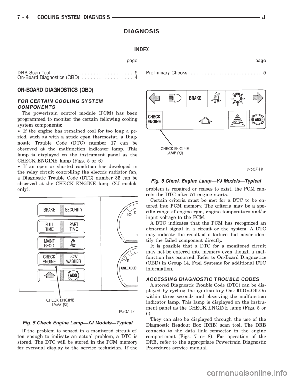
lamp is displayed on the instrument panel as the
CHECK ENGINE lamp (Figs. 5 or 6).
²If an open or shorted condition has developed in
the relay circuit controlling the electric radiator fan,
a Diagnostic Trouble Code (DTC) number 35 can be
observed at the CHECK ENGINE lamp (XJ models
only).
If the problem is sensed in a monitored circuit of-
ten enough to indicate an actual problem, a DTC is
stored. The DTC will be stored in the PCM memory
for eventual display to the service technician. If theproblem is repaired or ceases to exist, the PCM can-
cels the DTC after 51 engine starts.
Certain criteria must be met for a DTC to be en-
tered into PCM memory. The criteria may be a spe-
cific range of engine rpm, engine temperature and/or
input voltage to the PCM.
A DTC indicates that the PCM has recognized an
abnormal signal in a circuit or the system. A DTC
may indicate the result of a failure, but never iden-
tify the failed component directly.
It is possible that a DTC for a monitored circuit
may not be entered into memory even though a mal-
function has occurred. Refer to On-Board Diagnostics
(OBD) in Group 14, Fuel Systems for additional DTC
information.
ACCESSING DIAGNOSTIC TROUBLE CODES
A stored Diagnostic Trouble Code (DTC) can be dis-
played by cycling the ignition key On-Off-On-Off-On
within three seconds and observing the malfunction
indicator lamp. This lamp is displayed on the instru-
ment panel as the CHECK ENGINE lamp (Figs. 5 or
6).
They can also be displayed through the use of the
Diagnostic Readout Box (DRB) scan tool. The DRB
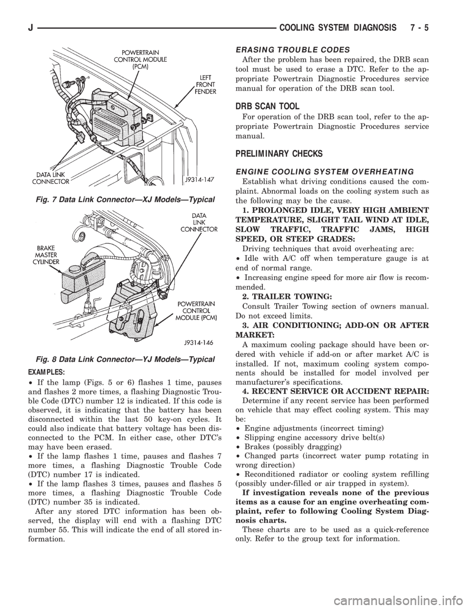
connects to the data link connector in the engine
compartment (Figs. 7 or 8). For operation of the
DRB, refer to the appropriate Powertrain Diagnostic
Procedures service manual.
Fig. 5 Check Engine LampÐXJ ModelsÐTypical
Fig. 6 Check Engine LampÐYJ ModelsÐTypical
7 - 4 COOLING SYSTEM DIAGNOSISJ
Page 244 of 2158
EXAMPLES:
²If the lamp (Figs. 5 or 6) flashes 1 time, pauses
and flashes 2 more times, a flashing Diagnostic Trou-
ble Code (DTC) number 12 is indicated. If this code is
observed, it is indicating that the battery has been
disconnected within the last 50 key-on cycles. It
could also indicate that battery voltage has been dis-
connected to the PCM. In either case, other DTC's
may have been erased.
²If the lamp flashes 1 time, pauses and flashes 7
more times, a flashing Diagnostic Trouble Code
(DTC) number 17 is indicated.
²If the lamp flashes 3 times, pauses and flashes 5
more times, a flashing Diagnostic Trouble Code
(DTC) number 35 is indicated.
After any stored DTC information has been ob-
served, the display will end with a flashing DTC
number 55. This will indicate the end of all stored in-
formation.
ERASING TROUBLE CODES
After the problem has been repaired, the DRB scan
tool must be used to erase a DTC. Refer to the ap-
propriate Powertrain Diagnostic Procedures service
manual for operation of the DRB scan tool.
DRB SCAN TOOL
For operation of the DRB scan tool, refer to the ap-
propriate Powertrain Diagnostic Procedures service
manual.
PRELIMINARY CHECKS
ENGINE COOLING SYSTEM OVERHEATING
Establish what driving conditions caused the com-
plaint. Abnormal loads on the cooling system such as
the following may be the cause.
1. PROLONGED IDLE, VERY HIGH AMBIENT
TEMPERATURE, SLIGHT TAIL WIND AT IDLE,
SLOW TRAFFIC, TRAFFIC JAMS, HIGH
SPEED, OR STEEP GRADES:
Driving techniques that avoid overheating are:
²Idle with A/C off when temperature gauge is at
end of normal range.
²Increasing engine speed for more air flow is recom-
mended.
2. TRAILER TOWING:
Consult Trailer Towing section of owners manual.
Do not exceed limits.
3. AIR CONDITIONING; ADD-ON OR AFTER
MARKET:
A maximum cooling package should have been or-
dered with vehicle if add-on or after market A/C is
installed. If not, maximum cooling system compo-
nents should be installed for model involved per
manufacturer's specifications.
4. RECENT SERVICE OR ACCIDENT REPAIR:
Determine if any recent service has been performed
on vehicle that may effect cooling system. This may
be:
²Engine adjustments (incorrect timing)
²Slipping engine accessory drive belt(s)
²Brakes (possibly dragging)
²Changed parts (incorrect water pump rotating in
wrong direction)
²Reconditioned radiator or cooling system refilling
(possibly under-filled or air trapped in system).
If investigation reveals none of the previous
items as a cause for an engine overheating com-
plaint, refer to following Cooling System Diag-
nosis charts.
These charts are to be used as a quick-reference
only. Refer to the group text for information.
Fig. 7 Data Link ConnectorÐXJ ModelsÐTypical
Fig. 8 Data Link ConnectorÐYJ ModelsÐTypical
JCOOLING SYSTEM DIAGNOSIS 7 - 5
Page 257 of 2158
temperature, coolant is allowed to flow to the radia-
tor. This provides quick engine warmup and overall
temperature control.
An arrow plus the wordUPis stamped on the
front flange next to the air bleed. The wordsTO
RADare stamped on one arm of the thermostat.
They indicate the proper installed position.
The same thermostat is used for winter and sum-
mer seasons. An engine should not be operated with-
out a thermostat, except for servicing or testing.
Operating without a thermostat causes other prob-
lems. These are: longer engine warmup time, unreli-
able warmup performance, increased exhaust
emissions and crankcase condensation. This conden-
sation can result in sludge formation.
CAUTION: Do not operate an engine without a ther-
mostat, except for servicing or testing.
ON-BOARD DIAGNOSTICS
XJ and YJ models are equipped with On-Board Di-
agnostics for certain cooling system components. Re-
fer to On-Board Diagnostics (OBD) in the Diagnosis
section of this group for additional information. If the
powertrain control module (PCM) detects low engine
coolant temperature, it will record a Diagnostic Trou-
ble Code (DTC) in the PCM memory. The DTC num-
ber for low coolant temperature is 17. Do not change
a thermostat for lack of heat as indicated by the in-
strument panel gauge or heater performance unless a
DTC number 17 is present. Refer to the Diagnosis
section of this group for other probable causes. For
other DTC numbers, refer to On-Board Diagnostics
in the General Diagnosis section of Group 14, Fuel
Systems.
The DTC can also be accessed through the DRB
scan tool. Refer to the appropriate Powertrain Diag-
nostic Procedures manual for diagnostic information
and operation of the DRB scan tool.
REMOVAL
WARNING: DO NOT LOOSEN THE RADIATOR
DRAINCOCK WITH THE SYSTEM HOT AND PRES-
SURIZED. SERIOUS BURNS FROM THE COOLANT
CAN OCCUR.
DO NOT WASTE reusable coolant. If the solution
is clean, drain the coolant into a clean container for
reuse.
(1) Drain the coolant from the radiator until the
level is below the thermostat housing.
WARNING: CONSTANT TENSION HOSE CLAMPS
ARE USED ON MOST COOLING SYSTEM HOSES.
WHEN REMOVING OR INSTALLING, USE ONLY
TOOLS DESIGNED FOR SERVICING THIS TYPE OF
CLAMP, SUCH AS SPECIAL CLAMP TOOL (NUMBER
6094) (FIG. 15). SNAP-ON CLAMP TOOL (NUMBER
HPC-20) MAY BE USED FOR LARGER CLAMPS. AL-
WAYS WEAR SAFETY GLASSES WHEN SERVICING
CONSTANT TENSION CLAMPS.
CAUTION: A number or letter is stamped into the
tongue of constant tension clamps (Fig. 16). If re-
placement is necessary, use only an original equip-
ment clamp with matching number or letter.
(2) Remove radiator upper hose and heater hose at
thermostat housing.
(3) Disconnect wiring connector at engine coolant
temperature sensor.
(4) Remove thermostat housing mounting bolts,
thermostat housing, gasket and thermostat (Fig. 17).
Discard old gasket.
(5) Clean the gasket mating surfaces.
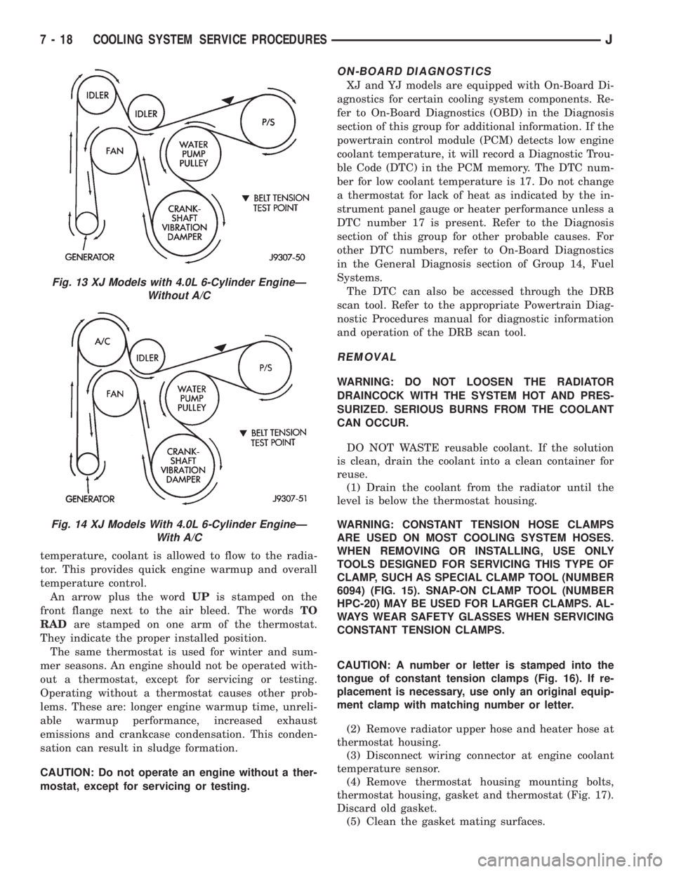
Fig. 13 XJ Models with 4.0L 6-Cylinder EngineÐ
Without A/C
Fig. 14 XJ Models With 4.0L 6-Cylinder EngineÐ
With A/C
7 - 18 COOLING SYSTEM SERVICE PROCEDURESJ
Page 274 of 2158
(5) Be sure that the air conditioner (if equipped) is
turned off.
WARNING: USE EXTREME CAUTION WHEN THE
ENGINE IS OPERATING. DO NOT STAND IN A DI-
RECT LINE WITH THE FAN. DO NOT PUT YOUR
HANDS NEAR THE PULLEYS, BELTS OR FAN. DO
NOT WEAR LOOSE CLOTHING.
(6) Start the engine and operate at 2400 rpm.
Within ten minutes the air temperature (indicated on
the dial thermometer) should be up to 88É C (190É F).
Fan driveengagementshould have started to occur
at between 74É to 82É C (165É to 180É F). Engage-
ment is distinguishable by a definiteincreasein fan
flow noise (roaring). The timing light also will indi-
cate an increase in the speed of the fan.
(7) When the air temperature reaches 88É C (190É
F), remove the plastic sheet. Fan drivedisengage-
mentshould have started to occur at between 57É to
79É C (135É to 175É F). A definitedecreaseof fan
flow noise (roaring) should be noticed. If not, replace
the defective viscous fan drive unit.
VISCOUS FAN DRIVE REMOVAL/INSTALLATION
Refer to the previous section on Cooling System
Fan for removal and installation procedures of the
viscous drive unit.
Viscous Fan Drive Fluid Pump Out Require-
ment:After installing anewviscous fan drive, bring
the engine speed up to approximately 2000 rpm and
hold for approximately two minutes. This will ensure
proper fluid distribution within the drive.
AUXILIARY ELECTRIC COOLING FANÐXJ MODELS
WITH 4.0L 6-CYLINDER ENGINE
OPERATION
XJ models equipped with a 4.0L 6-cylinder engine
may also have an auxiliary electrical cooling fan.
This is with models that have air conditioning and/or
heavy duty cooling. The fan is controlled by the cool-
ing fan relay, which is located in the power distribu-
tion center (PDC). For the location of relay within
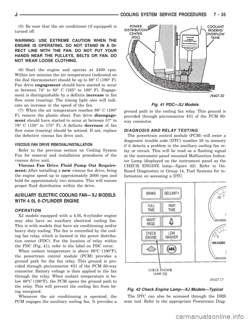
the PDC (Fig. 41), refer to the label on PDC cover.
When coolant temperature is above 88ÉC (190ÉF),
the powertrain control module (PCM) provides a
ground path for the fan relay. This ground is pro-
vided through pin/connector #31 of the PCM 60-way
connector. Battery voltage is then applied to the fan
through the relay. When coolant temperature is be-
low 88ÉC (190ÉF), the PCM opens the ground path to
the relay. This will prevent the cooling fan from be-
ing energized.
Whenever the air conditioning is operated, the
PCM engages the auxiliary cooling fan. It provides aground path to the cooling fan relay. This ground is
provided through pin/connector #31 of the PCM 60-
way connector.
DIAGNOSIS AND RELAY TESTING
The powertrain control module (PCM) will enter a
diagnostic trouble code (DTC) number 35 in memory
if it detects a problem in the auxiliary cooling fan re-
lay or circuit. This will be read as a flashing signal
at the instrument panel mounted Malfunction Indica-
tor Lamp (displayed on the instrument panel as the
CHECK ENGINE lampÐfigure 42). Refer to On-
Board Diagnostics in Group 14, Fuel Systems for in-
formation on accessing a DTC.
The DTC can also be accessed through the DRB
scan tool. Refer to the appropriate Powertrain Diag-
Fig. 41 PDCÐXJ Models
Fig. 42 Check Engine LampÐXJ ModelsÐTypical
JCOOLING SYSTEM SERVICE PROCEDURES 7 - 35
Page 286 of 2158
ELECTRICAL
GROUP INDEX
Group Group
AUDIO SYSTEMS........................ 8F
BATTERY/STARTER/GENERATOR SERVICE.... 8B
BATTERY/STARTING/CHARGING SYSTEMS
DIAGNOSTICS......................... 8A
CHIME/BUZZER WARNING SYSTEMS........ 8U
HORNS................................ 8G
IGNITION SYSTEMS...................... 8D
INSTRUMENT PANEL AND GAUGES......... 8E
LAMPS................................ 8L
OVERHEAD CONSOLE.................... 8C
POWER LOCKS.......................... 8P
POWER MIRRORS....................... 8TPOWER SEATS.......................... 8R
POWER WINDOWS....................... 8S
REAR WINDOW DEFOGGER............... 8N
RESTRAINT SYSTEMS................... 8M
TURN SIGNAL AND HAZARD WARNING
SYSTEMS............................. 8J
VEHICLE SPEED CONTROL SYSTEM......... 8H
WIPER AND WASHER SYSTEMS............ 8K
XJ WIRING DIAGRAMS-LEFT HAND DRIVE . . . 8W
XJ WIRING DIAGRAMS-RIGHT HAND DRIVE . 8W
YJ WIRING DIAGRAMS.................. 8W
BATTERY/STARTING/CHARGING SYSTEMS DIAGNOSTICS
CONTENTS
page page
BATTERY............................... 2
CHARGING SYSTEM..................... 17
IGNITION-OFF DRAW.................... 10SPECIFICATIONS........................ 23
STARTING SYSTEM...................... 11
USING ON-BOARD DIAGNOSTIC SYSTEM.... 22
GENERAL INFORMATION
The battery, starting, and charging systems operate
with one another; therefore, they must be tested as a
complete system. In order for the vehicle to start and
charge properly, all of the components involved in
these systems must perform within specifications.
Group 8A covers battery, starting (Fig. 1) and
charging (Fig. 2) system diagnostic procedures. These
procedures include the most basic conventional diag-
nostic methods, to On-Board Diagnostics (OBD) builtinto the Powertrain Control Module (PCM). Use of an
induction milliamp ammeter, volt/ohmmeter, battery
charger, carbon pile rheostat (load tester), and 12-
volt test lamp will be required.
All OBD-sensed systems are monitored by the
PCM. Each monitored circuit is assigned a Diagnos-
tic Trouble Code (DTC). The PCM will store a DTC in
electronic memory for any failure it detects. See Us-
ing On-Board Diagnostic System in this group for
more information.
JELECTRICAL 8A - 1
Page 307 of 2158
USING ON-BOARD DIAGNOSTIC SYSTEM
GENERAL INFORMATION
The Powertrain Control Module (PCM) monitors
critical input and output circuits of the charging sys-
tem, making sure they are operational. A Diagnostic
Trouble Code (DTC) is assigned to each input and
output circuit monitored by the OBD system. Some
circuits are checked continuously and some are
checked only under certain conditions.
If the OBD system senses that a monitored circuit
is bad, it will put a DTC into electronic memory. The
DTC will stay in electronic memory as long as the
circuit continues to be bad. The PCM is programmed
to clear the memory after 50 engine starts, if the
problem does not occur again.
DIAGNOSTIC TROUBLE CODES
Diagnostic Trouble Codes (DTC) are two-digit num-
bers flashed on the malfunction indicator (Check En-
gine) lamp that identify which circuit is bad. A DTC
description can also be read using the DRB scan tool.
Refer to Group 14 - Fuel Systems for more informa-
tion.
A DTC does not identify which component in a cir-
cuit is bad. Thus, a DTC should be treated as a
symptom, not as the cause for the problem. In some
cases, because of the design of the diagnostic test
procedure, a DTC can be the reason for another DTCto be set. Therefore, it is important that the test pro-
cedures be followed in sequence, to understand what
caused a DTC to be set.
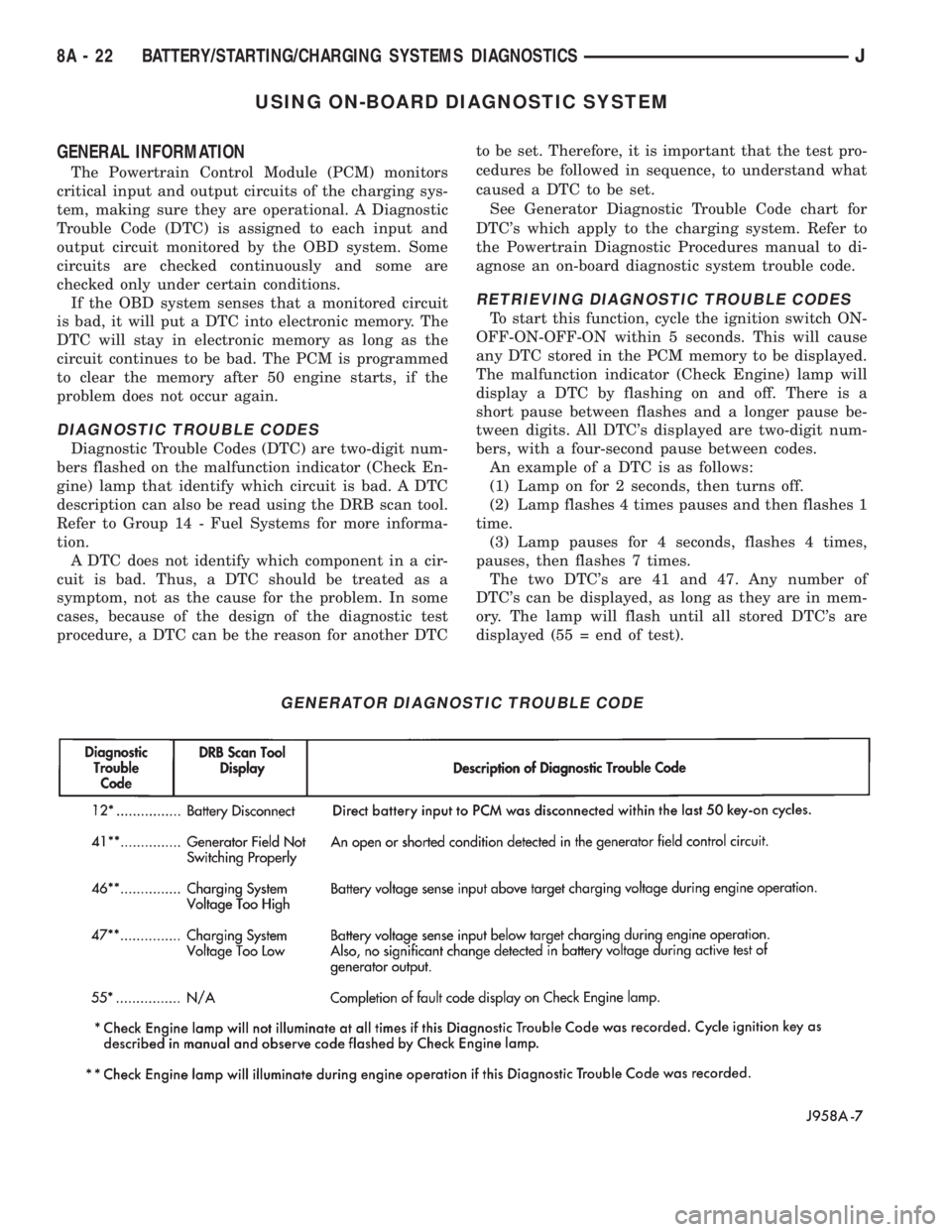
See Generator Diagnostic Trouble Code chart for
DTC's which apply to the charging system. Refer to
the Powertrain Diagnostic Procedures manual to di-
agnose an on-board diagnostic system trouble code.
RETRIEVING DIAGNOSTIC TROUBLE CODES
To start this function, cycle the ignition switch ON-
OFF-ON-OFF-ON within 5 seconds. This will cause
any DTC stored in the PCM memory to be displayed.
The malfunction indicator (Check Engine) lamp will
display a DTC by flashing on and off. There is a
short pause between flashes and a longer pause be-
tween digits. All DTC's displayed are two-digit num-
bers, with a four-second pause between codes.
An example of a DTC is as follows:
(1) Lamp on for 2 seconds, then turns off.
(2) Lamp flashes 4 times pauses and then flashes 1
time.
(3) Lamp pauses for 4 seconds, flashes 4 times,
pauses, then flashes 7 times.
The two DTC's are 41 and 47. Any number of
DTC's can be displayed, as long as they are in mem-
ory. The lamp will flash until all stored DTC's are
displayed (55 = end of test).
GENERATOR DIAGNOSTIC TROUBLE CODE
8A - 22 BATTERY/STARTING/CHARGING SYSTEMS DIAGNOSTICSJ
Page 314 of 2158
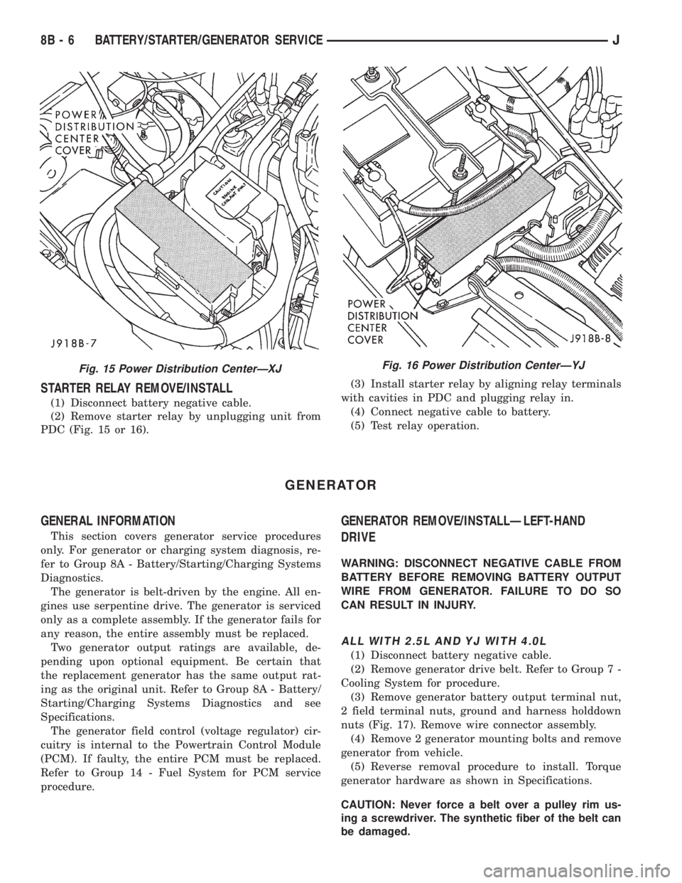
STARTER RELAY REMOVE/INSTALL
(1) Disconnect battery negative cable.
(2) Remove starter relay by unplugging unit from
PDC (Fig. 15 or 16).(3) Install starter relay by aligning relay terminals
with cavities in PDC and plugging relay in.
(4) Connect negative cable to battery.
(5) Test relay operation.
GENERATOR
GENERAL INFORMATION
This section covers generator service procedures
only. For generator or charging system diagnosis, re-
fer to Group 8A - Battery/Starting/Charging Systems
Diagnostics.
The generator is belt-driven by the engine. All en-
gines use serpentine drive. The generator is serviced
only as a complete assembly. If the generator fails for
any reason, the entire assembly must be replaced.
Two generator output ratings are available, de-
pending upon optional equipment. Be certain that
the replacement generator has the same output rat-
ing as the original unit. Refer to Group 8A - Battery/
Starting/Charging Systems Diagnostics and see
Specifications.
The generator field control (voltage regulator) cir-
cuitry is internal to the Powertrain Control Module
(PCM). If faulty, the entire PCM must be replaced.
Refer to Group 14 - Fuel System for PCM service
procedure.
GENERATOR REMOVE/INSTALLÐLEFT-HAND
DRIVE
WARNING: DISCONNECT NEGATIVE CABLE FROM
BATTERY BEFORE REMOVING BATTERY OUTPUT
WIRE FROM GENERATOR. FAILURE TO DO SO
CAN RESULT IN INJURY.
ALL WITH 2.5L AND YJ WITH 4.0L
(1) Disconnect battery negative cable.
(2) Remove generator drive belt. Refer to Group 7 -
Cooling System for procedure.
(3) Remove generator battery output terminal nut,
2 field terminal nuts, ground and harness holddown
nuts (Fig. 17). Remove wire connector assembly.
(4) Remove 2 generator mounting bolts and remove
generator from vehicle.
(5) Reverse removal procedure to install. Torque
generator hardware as shown in Specifications.
CAUTION: Never force a belt over a pulley rim us-
ing a screwdriver. The synthetic fiber of the belt can
be damaged.
Fig. 15 Power Distribution CenterÐXJFig. 16 Power Distribution CenterÐYJ
8B - 6 BATTERY/STARTER/GENERATOR SERVICEJ
Page 325 of 2158

IGNITION SYSTEMS
CONTENTS
page page
COMPONENT IDENTIFICATION/SYSTEM
OPERATION........................... 1
COMPONENT REMOVAL/INSTALLATION...... 17
DIAGNOSTICS/SERVICE PROCEDURES....... 6IGNITION SWITCHÐXJ MODELS........... 26
IGNITION SWITCHÐYJ MODELS........... 29
SPECIFICATIONS........................ 32
COMPONENT IDENTIFICATION/SYSTEM OPERATION
INDEX
page page
Automatic Shutdown (ASD) Relay.............. 1
Camshaft Position Sensor.................... 2
Crankshaft Position Sensor................... 3
Distributors............................... 4
Engine Coolant Temperature Sensor............ 5
General Information........................ 1Ignition Coil.............................. 4
Intake Manifold Air Temperature Sensor.......... 5
Manifold Absolute Pressure (MAP) Sensor........ 5
Oxygen (O2S) Sensor....................... 5
Powertrain Control Module (PCM).............. 5
Throttle Position Sensor..................... 5
GENERAL INFORMATION
Throughout this group, references are made to par-
ticular vehicle models by alphabetical designation
(XJ or YJ) or by the particular vehicle nameplate. A
chart showing a breakdown of alphabetical designa-
tions is included in the Introduction group at the be-
ginning of this manual.
This section of the group, Component Identifica-
tion/System Operation, will discuss ignition system
operation and will identify ignition system compo-
nents.
For diagnostic procedures and adjustments, refer to
the Diagnostics/Service Procedures section of this
group.
For removal and installation of ignition system
components, refer to the Component Removal/Instal-
lation section of this group.
For other useful information, refer to On-Board Di-
agnostics in the General Diagnosis sections of Group
14, Fuel System in this manual.
For operation of the DRB Scan Tool, refer to the
appropriate Powertrain Diagnostic Procedures ser-
vice manual.
An Ignition specifications section is included at the
end of this group. A general Maintenance Schedule
(mileage intervals) for ignition related items can be
found in Group 0, Lubrication and Maintenance. This
schedule can also be found in the Owners Manual.
IGNITION SYSTEMS
A multi-port, fuel injected engine is used on all
models. The ignition system is controlled by the pow-
ertrain control module (PCM) on all engines. The
PCM was formerly referred to as the SBEC or engine
controller.
The ignition system consists of:
²Spark plugs
²Ignition coil
²Secondary ignition cables
²Distributor (contains rotor and camshaft position
sensor)
²Powertrain control module (PCM)
²Crankshaft position sensor
AUTOMATIC SHUTDOWN (ASD) RELAY
The automatic shutdown (ASD) relay is located in
the power distribution center (PDC) near the battery
(Fig. 1 or 2). As one of its functions, it will supply
battery voltage to the ignition coil.
The ground circuit for the ASD relay is controlled
by the powertrain control module (PCM). This is
done through pin/cavity number 51 of the PCM 60-
way connector. The PCM then regulates ASD relay
operation by switching this ground circuit on-and-off.
Also refer to Ignition Coil for additional informa-
tion.
JIGNITION SYSTEMS 8D - 1