1995 JEEP XJ air condition
[x] Cancel search: air conditionPage 164 of 2158

connect scan tool and proceed to next step.
(7)Repeatconventional bleed procedure described
in steps (4) and (5).
(8) Top off master cylinder fluid level and verify
proper brake operation before moving vehicle.
BRAKELINES AND HOSES
Metal brakelines and rubber brake hoses should be
inspected periodically and replaced if damaged.
Rubber brake hoses should be replaced if cut,
cracked, swollen, or leaking. Rubber hoses must be
replaced as they are not repairable.
Steel brakelines should be inspected any time the
vehicle is in for normal maintenance. This is impor-
tant on high mileage vehicles. It is especially impor-
tant when the vehicle is operated on roads that are
salted during winter months.
Heavily rusted/corroded brake rotors, drums,
support plates, and brakelines should be
cleaned and carefully inspected. Heavy rust
buildup can hide severe damage to a compo-
nent. Severely rusted parts should be replaced
if condition is suspect.
BRAKELINE CHARTS
Brakeline routing and connections are displayed in
Figures 4 through 10. Routing for both right hand drive
(RHD) and left hand drive (LHD) models is provided.
Fig. 4 Brakeline Routing (YJ With ABS)
Fig. 5 Front Brake Hose And Sensor Wire Routing
(RHD XJ With ABS)
5 - 12 BRAKE FLUIDÐBRAKE BLEEDINGÐBRAKELINES AND HOSESJ
Page 168 of 2158
(2) Disconnect brake lines at master cylinder and
combination valve.
(3) Remove nuts attaching master cylinder to
booster studs.
(4) Remove master cylinder.
(5) Remove cylinder cover and drain fluid.
(6) If two-piece master cylinder reservoir requires
service, refer to reservoir replacement procedure in
this section.
MASTER CYLINDER INSTALLATION (NON-ABS)
(1) Bleed master cylinder on bench before installa-
tion. Refer to procedure in this section.
(2) If new two-piece master cylinder is being in-
stalled, remove plastic protective sleeve from primary
piston shank. Also check condition of seal at rear of
cylinder body. Reposition seal if dislodged. Replace
seal if cut, or torn.
(3) Clean cylinder mounting surface of brake booster.
Use shop towel wetted with brake cleaner for this pur-
pose. Dirt, grease, or similar materials will prevent
proper cylinder seating and could result in vacuum leak.
(4) Slide master cylinder onto brake booster studs.
(5) Install nuts attaching master cylinder to booster
studs. Tighten nuts to 25 Nzm (220 in. lbs.) torque.
(6) Connect brakelines to master cylinder and com-
bination valve (Figs. 1 and 2).
(7) Fill and bleed brake system.
COMBINATION VALVE REPLACEMENT (NON-ABS)
The combination valve is not a repairable compo-
nent. The valve is serviced as an assembly whenever
diagnosis indicates replacement is necessary.
(1) Remove air cleaner cover and hose for access to
valve, if necessary.
(2) Disconnect differential pressure switch wire at
combination valve. Do not pull switch wire to discon-
nect. Unsnap connecter lock tabs to remove.
(3) Disconnect brakelines at combination valve and
remove valve.
(4) Connect brakelines to replacement valve. Start
line fittings by hand to avoid cross threading.
Tighten fittings snug but not to required torque at
this time.
(5) Connect wire to pressure differential switch.
(6) Bleed brakes.
(7) Tighten brakeline fittings to 18-24 Nzm
(160-210 in. lbs.) torque after bleeding.
MASTER CYLINDER OVERHAUL (4-CYLINDER
MODELS)
CYLINDER DISASSEMBLY
(1) Examine cylinder cover seal. Discard seal if
torn or distorted.
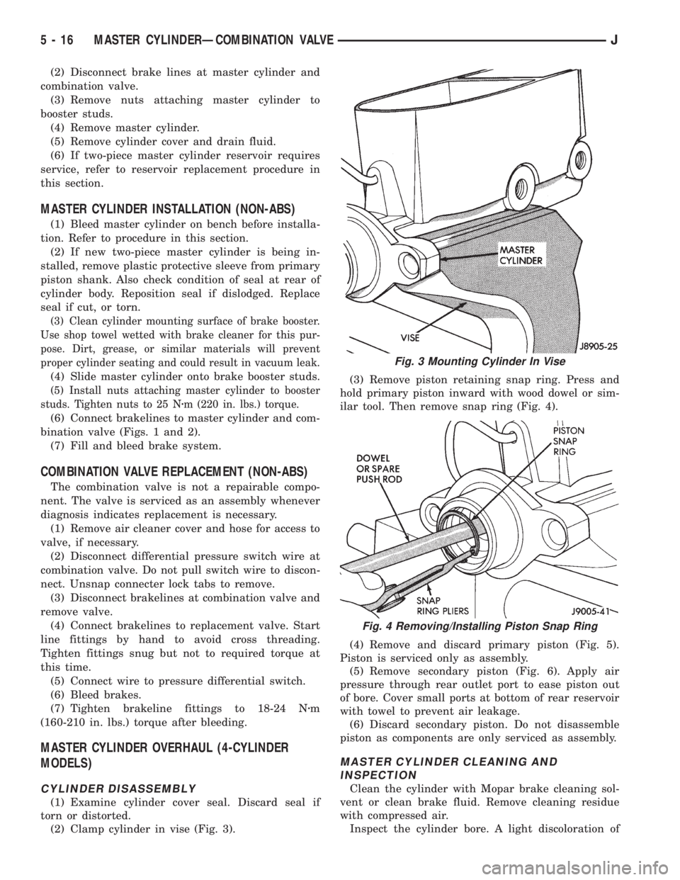
(2) Clamp cylinder in vise (Fig. 3).(3) Remove piston retaining snap ring. Press and
hold primary piston inward with wood dowel or sim-
ilar tool. Then remove snap ring (Fig. 4).
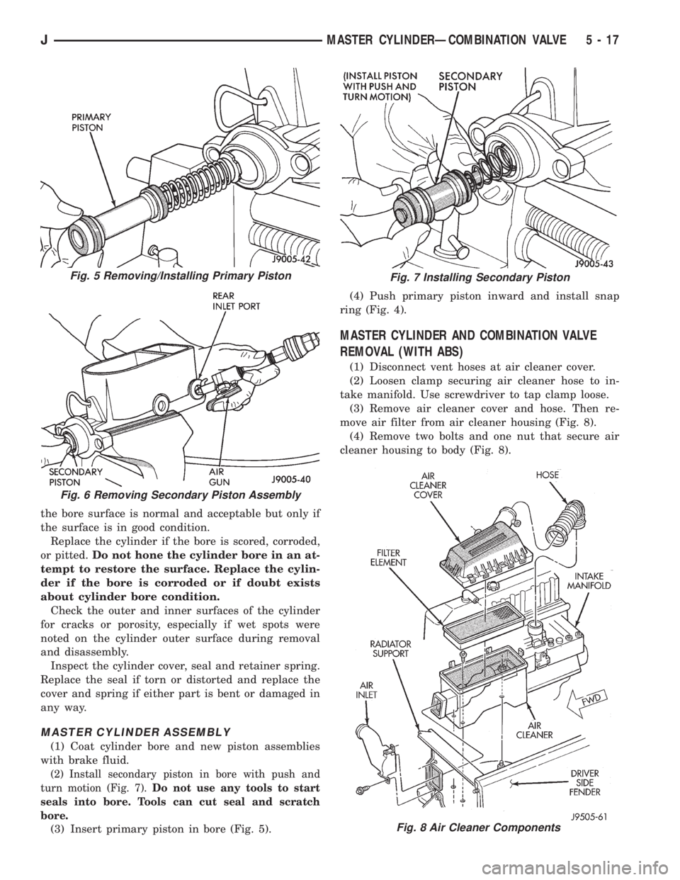
(4) Remove and discard primary piston (Fig. 5).
Piston is serviced only as assembly.
(5) Remove secondary piston (Fig. 6). Apply air
pressure through rear outlet port to ease piston out
of bore. Cover small ports at bottom of rear reservoir
with towel to prevent air leakage.
(6) Discard secondary piston. Do not disassemble
piston as components are only serviced as assembly.
MASTER CYLINDER CLEANING AND
INSPECTION
Clean the cylinder with Mopar brake cleaning sol-
vent or clean brake fluid. Remove cleaning residue
with compressed air.
Inspect the cylinder bore. A light discoloration of
Fig. 3 Mounting Cylinder In Vise
Fig. 4 Removing/Installing Piston Snap Ring
5 - 16 MASTER CYLINDERÐCOMBINATION VALVEJ
Page 169 of 2158
the bore surface is normal and acceptable but only if
the surface is in good condition.
Replace the cylinder if the bore is scored, corroded,
or pitted.Do not hone the cylinder bore in an at-
tempt to restore the surface. Replace the cylin-
der if the bore is corroded or if doubt exists
about cylinder bore condition.
Check the outer and inner surfaces of the cylinder
for cracks or porosity, especially if wet spots were
noted on the cylinder outer surface during removal
and disassembly.
Inspect the cylinder cover, seal and retainer spring.
Replace the seal if torn or distorted and replace the
cover and spring if either part is bent or damaged in
any way.
MASTER CYLINDER ASSEMBLY
(1) Coat cylinder bore and new piston assemblies
with brake fluid.
(2) Install secondary piston in bore with push and
turn motion (Fig. 7).Do not use any tools to start
seals into bore. Tools can cut seal and scratch
bore.
(3) Insert primary piston in bore (Fig. 5).(4) Push primary piston inward and install snap
ring (Fig. 4).
MASTER CYLINDER AND COMBINATION VALVE
REMOVAL (WITH ABS)
(1) Disconnect vent hoses at air cleaner cover.
(2) Loosen clamp securing air cleaner hose to in-
take manifold. Use screwdriver to tap clamp loose.
(3) Remove air cleaner cover and hose. Then re-
move air filter from air cleaner housing (Fig. 8).
(4) Remove two bolts and one nut that secure air
cleaner housing to body (Fig. 8).
Fig. 8 Air Cleaner Components
Fig. 5 Removing/Installing Primary Piston
Fig. 6 Removing Secondary Piston Assembly
Fig. 7 Installing Secondary Piston
JMASTER CYLINDERÐCOMBINATION VALVE 5 - 17
Page 182 of 2158
(11) Remove nuts attaching booster to passenger
compartment side of dash panel.
(12) In engine compartment, slide booster studs
out of dash panel, tilt booster upward, and remove
booster from engine compartment.
(13) Remove dash seal from booster.
(14) If booster is only being removed for access to
other components, cover booster front opening with
clean shop towel.
POWER BRAKE BOOSTER INSTALLATION (XJ
WITHOUT ABS)
(1) If original booster is being installed, test check
valve with vacuum tool before booster installation.
Replace check valve if it will not hold vacuum.
(2) Install dash seal on booster.
(3) Align and position booster on dash panel (Fig.
17).
(4) In passenger compartment, install nuts that at-
tach booster to dash panel. Tighten nuts just enough
to hold booster in place.
(5) Slide booster push rod onto brake pedal. Then
secure push rod to pedal pin with retaining clip.
(6) Tighten booster attaching nuts to 41 Nzm (30 ft.
lbs.) on XJ and 34 Nzm (25 ft. lbs.) on YJ.
(7) Install instrument panel lower trim cover.
(8) If original master cylinder is being installed,
check condition of seal at rear of master cylinder
(Fig. 18). Clean and reposition seal if dislodged. Re-
place seal if cut, or torn.
(9) Clean cylinder mounting surface of brake
booster. Use shop towel wetted with brake cleaner for
this purpose. Dirt, grease, or similar materials will
prevent proper cylinder seating and could result in
vacuum leak.
(10) Align and install master cylinder on booster
studs. Tighten cylinder attaching nuts to 13-25 Nzm
(115-220 in. lbs.) torque.
(11) Connect vacuum hose to booster check valve.
(12) Connect and secure brakelines to combination
valve and master cylinder. Start all brakeline fittings
by hand to avoid cross threading.
(13) If combination valve has integral bracket, po-
sition bracket on booster studs. Then install and
tighten bracket attaching nuts to 13-25 Nzm (115-220
in. lbs.) torque.
(14) Connect wire to combination valve switch.
(15) Top off master cylinder fluid level.
(16) Bleed brakes. Refer to procedures in section
on brake bleeding.
(17) Install engine air cleaner and hoses.
(18) Verify proper brake operation before moving
vehicle.
POWER BRAKE BOOSTER REMOVAL (YJ)
(1) Disconnect brakelines at master cylinder. Then
loosen lines at combination valve and move lines
away from cylinder.
(2) Remove nuts master cylinder to booster studs.
(3) If combination valve has integral bracket, slide
bracket off studs and move valve aside.
(4) Remove master cylinder. Slide cylinder off
studs and remove it from engine compartment.
(5) Working under instrument panel, remove re-
tainer clip that secures booster push rod to brake
pedal.
(6) Disconnect vacuum hose at booster check valve.
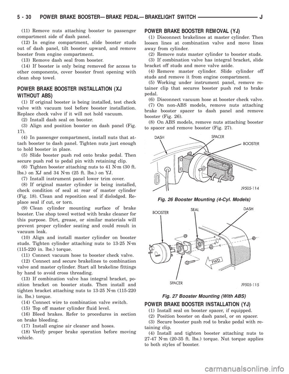
(7) On non-ABS models, remove nuts attaching
brake booster spacer to dash panel and remove
booster (Fig. 26).
(8) On ABS models, remove nuts attaching booster
to spacer and remove booster (Fig. 27).
POWER BRAKE BOOSTER INSTALLATION (YJ)
(1) Install seal on booster spacer, if equipped.
(2) Position booster on dash panel, or on spacer.
(3) Secure booster push rod to brake pedal with re-
taining clip.
(4) Install and tighten booster attaching nuts to
27-47 Nzm (20-35 ft. lbs.) torque. Nut torque applies
to both styles of booster.
Fig. 26 Booster Mounting (4-Cyl. Models)
Fig. 27 Booster Mounting (With ABS)
5 - 30 POWER BRAKE BOOSTERÐBRAKE PEDALÐBRAKELIGHT SWITCHJ
Page 188 of 2158

During normal braking, the master cylinder, power
booster and wheel brake units all function as they
would in a vehicle without ABS. The HCU compo-
nents are not activated.
ABS OPERATION IN ANTILOCK BRAKING MODE
The purpose of the antilock system is to prevent
wheel lockup during periods of high wheel slip. Pre-
venting lockup helps maintain vehicle braking action
and steering control.
The antilock ECU activates the system whenever
sensor signals indicate periods of high wheel slip.
High wheel slip can be described as the point where
wheel rotation begins approaching zero (or lockup)
during braking. Periods of high wheel slip may occur
when brake stops involve high pedal pressure and
rate of deceleration.
The antilock system prevents lockup during high
slip conditions by modulating fluid apply pressure to
the wheel brake units.
Brake fluid apply pressure is modulated according
to wheel speed, degree of slip and rate of decelera-
tion. A sensor at each wheel converts wheel speed
into electrical signals. These signals are transmitted
to the ECU for processing and determination of
wheel slip and deceleration rate.
The ABS system has three fluid pressure control
channels. The front brakes are controlled separately
and the rear brakes in tandem (Fig. 1). A speed sen-
sor input signal indicating a high slip condition acti-
vates the ECU antilock program.
Two solenoid valves are used in each antilock con-
trol channel. The valves are all located within the
HCU valve body and work in pairs to either increase,
hold, or decrease apply pressure as needed in the in-
dividual control channels.
The solenoid valves are not static during antilock
braking. They are cycled continuously to modulate
pressure. Solenoid cycle time in antilock mode can be
measured in milliseconds.
HCU OPERATION
Normal Braking
During normal braking, the HCU solenoid valves
and pump are not activated. The master cylinder and
power booster operate the same as a vehicle without
an ABS brake system.
Antilock Pressure Modulation
Solenoid valve pressure modulation occurs in three
stages which are: pressure increase, pressure hold,
and pressure decrease. The valves are all contained
in the valve body portion of the HCU.
Pressure Decrease
The outlet valve is opened and the inlet valve is
closed during the pressure decrease cycle (Fig. 6).A pressure decrease cycle is initiated when speed
sensor signals indicate high wheel slip at one or
more wheels. At this point, the ECU opens the outlet
valve, which also opens the return circuit to the ac-
cumulators. Fluid pressure is allowed to bleed off (de-
crease) as needed to prevent wheel lock.
Once the period of high wheel slip has ended, the
ECU closes the outlet valve and begins a pressure in-
crease or hold cycle as needed.
Pressure Hold
Both solenoid valves are closed in the pressure hold
cycle (Fig. 7). Fluid apply pressure in the control
channel is maintained at a constant rate. The ECU
maintains the hold cycle until sensor inputs indicate
a pressure change is necessary.
Pressure Increase
The inlet valve is open and the outlet valve is
closed during the pressure increase cycle (Fig. 8). The
pressure increase cycle is used to counteract unequal
wheel speeds. This cycle controls re-application of
fluid apply pressure due to changing road surfaces or
wheel speed.
Fig. 6 Pressure Decrease Cycle
5 - 36 ABS OPERATION AND SERVICEJ
Page 189 of 2158

WHEEL SPEED SENSOR OPERATION
Wheel speed input signals are generated by a sen-
sor and tone ring at each wheel. The sensors, which
are connected directly to the ECU, are mounted on
brackets attached to the front steering knuckles and
rear brake support plates.
The sensor triggering devices are the tone rings
which are similar in appearance to gears. The tone
rings are located on the outboard end of each front/rear axle shaft. The speed sensors generate a signal
whenever a tone ring tooth rotates past the sensor
pickup face.
The wheel speed sensors provide the input signal
to the ECU. If input signals indicate ABS mode brak-
ing, the ECU causes the HCU solenoids to decrease,
hold, or increase fluid apply pressure as needed.
The HCU solenoid valves are activated only when
wheel speed input signals indicate that a wheel is
approaching a high slip, or lockup condition. At this
point, the ECU will cycle the appropriate wheel con-
trol channel solenoid valves to prevent lockup.
The wheel sensors provide speed signals whenever
the vehicle wheels are rotating. The ECU examines
these signals for degree of deceleration and wheel
slip. If signals indicate normal braking, the solenoid
valves are not activated. However, when incoming
signals indicate the approach of wheel slip, or lockup,
the ECU cycles the solenoid valves as needed.
ACCELERATION SWITCH OPERATION
The ECU monitors the acceleration switch at all
times. The switch assembly contains three mercury
switches that monitor vehicle ride height and decel-
eration rates (G-force). Sudden, rapid changes in ve-
hicle and wheel deceleration rate, triggers the switch
sending a signal to the ECU. The switch assembly
provides three deceleration rates; two for forward
braking and one for rearward braking.
ECU OPERATION
The antilock ECU controls all phases of antilock
operation. It monitors and processes input signals
from the system sensors.
It is the ECU that activates the solenoid valves to
modulate apply pressure during antilock braking.
The ECU program is able to determine which wheel
control channel requires modulation and which fluid
pressure modulation cycle to use. The ECU cycles the
solenoid valves through the pressure decrease, hold
and increase phases.
ABS COMPONENT SERVICEABILITY
The ECU, acceleration sensor, wheel sensors, and
wire harnesses are serviced as assemblies only. The
axle shaft tone wheels are also not serviceable. If a
tone wheel becomes damaged, it will be necessary to
replace the axle shaft, or disc brake rotor and hub
assembly.
SPEED SENSOR AIR GAP
Front sensor air gap is fixed and not adjustable.
Only rear sensor air gap is adjustable.
Although front air gap is not adjustable, it can be
checked if diagnosis indicates this is necessary. Front
Fig. 7 Pressure Hold Cycle
Fig. 8 Pressure Increase Cycle
JABS OPERATION AND SERVICE 5 - 37
Page 193 of 2158
(2) Align and attach harness connector to ECU.
Slide connector into engagement with tangs on ECU.
Then tilt connector downward and into engagement
with ECU pin terminals. Exercise care as pin termi-
nals can be damaged if connector is forced into place.
(3) Connect harness to security alarm module, if
equipped.
(4) Position ECU bracket under instrument panel.
(5) Install and tighten ECU mounting bracket
bolts/nuts to 8-14 Nzm (75- 125 in. lbs.) torque.
(6) Install trim panel on instrument panel, if re-
moved.
ECU REMOVAL/INSTALLATION (YJ MODELS)
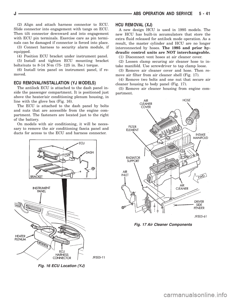
The antilock ECU is attached to the dash panel in-
side the passenger compartment. It is positioned just
above the heater/air conditioning plenum housing, in
line with the glove box (Fig. 16).
The ECU is attached to the dash panel by bolts
and nuts that are accessible from the engine com-
partment. The fasteners are located just to the right
of the battery.
On models with air conditioning, it will be neces-
sary to remove the air conditioning fascia panel and
ducts for access to the ECU and harness connecter.
HCU REMOVAL (XJ)
A new design HCU is used in 1995 models. The
new HCU has built-in accumulators that store the
extra fluid released for antilock mode operation. As a
result, the master cylinder and HCU are no longer
interconnected by hoses.The 1995 and prior hy-
draulic control units are NOT interchangeable.
(1) Disconnect vent hoses at air cleaner cover.
(2) Loosen clamp securing air cleaner hose to in-
take manifold. Use screwdriver to tap clamp loose.
(3) Remove air cleaner cover and hose. Then re-
move air filter from air cleaner shell (Fig. 17).
(4) Remove two bolts and one nut that secure air
cleaner housing to body panel (Fig. 17).
(5) Remove air cleaner housing from engine com-
partment.
Fig. 16 ECU Location (YJ)
Fig. 17 Air Cleaner Components
JABS OPERATION AND SERVICE 5 - 41
Page 199 of 2158
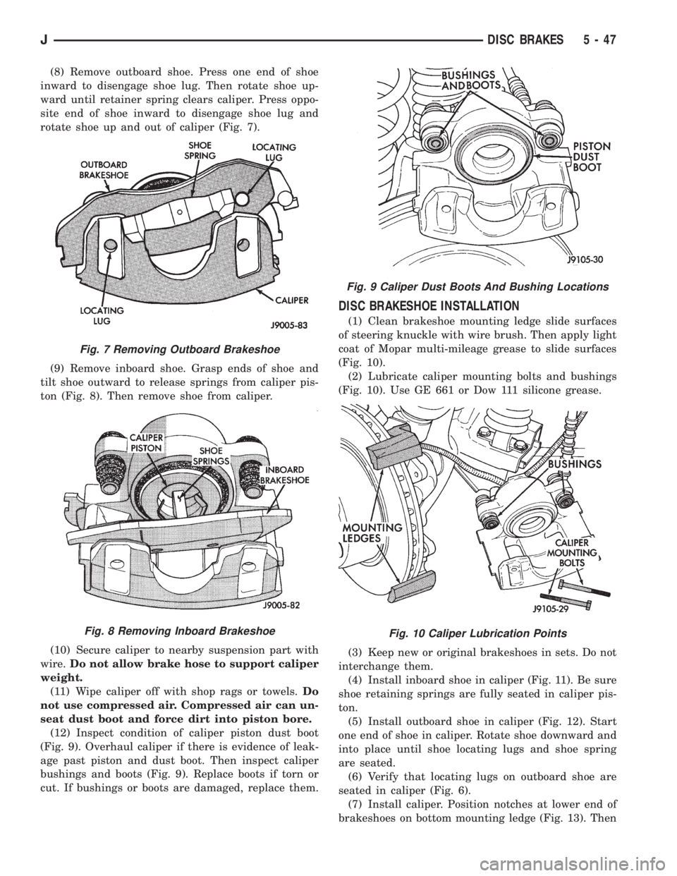
(8) Remove outboard shoe. Press one end of shoe
inward to disengage shoe lug. Then rotate shoe up-
ward until retainer spring clears caliper. Press oppo-
site end of shoe inward to disengage shoe lug and
rotate shoe up and out of caliper (Fig. 7).
(9) Remove inboard shoe. Grasp ends of shoe and
tilt shoe outward to release springs from caliper pis-
ton (Fig. 8). Then remove shoe from caliper.
(10) Secure caliper to nearby suspension part with
wire.Do not allow brake hose to support caliper
weight.
(11) Wipe caliper off with shop rags or towels.Do
not use compressed air. Compressed air can un-
seat dust boot and force dirt into piston bore.
(12) Inspect condition of caliper piston dust boot
(Fig. 9). Overhaul caliper if there is evidence of leak-
age past piston and dust boot. Then inspect caliper
bushings and boots (Fig. 9). Replace boots if torn or
cut. If bushings or boots are damaged, replace them.
DISC BRAKESHOE INSTALLATION
(1) Clean brakeshoe mounting ledge slide surfaces
of steering knuckle with wire brush. Then apply light
coat of Mopar multi-mileage grease to slide surfaces
(Fig. 10).
(2) Lubricate caliper mounting bolts and bushings
(Fig. 10). Use GE 661 or Dow 111 silicone grease.
(3) Keep new or original brakeshoes in sets. Do not
interchange them.
(4) Install inboard shoe in caliper (Fig. 11). Be sure
shoe retaining springs are fully seated in caliper pis-
ton.
(5) Install outboard shoe in caliper (Fig. 12). Start
one end of shoe in caliper. Rotate shoe downward and
into place until shoe locating lugs and shoe spring
are seated.
(6) Verify that locating lugs on outboard shoe are
seated in caliper (Fig. 6).
(7) Install caliper. Position notches at lower end of
brakeshoes on bottom mounting ledge (Fig. 13). Then
Fig. 7 Removing Outboard Brakeshoe
Fig. 8 Removing Inboard Brakeshoe
Fig. 9 Caliper Dust Boots And Bushing Locations
Fig. 10 Caliper Lubrication Points
JDISC BRAKES 5 - 47