1995 JEEP XJ air condition
[x] Cancel search: air conditionPage 281 of 2158

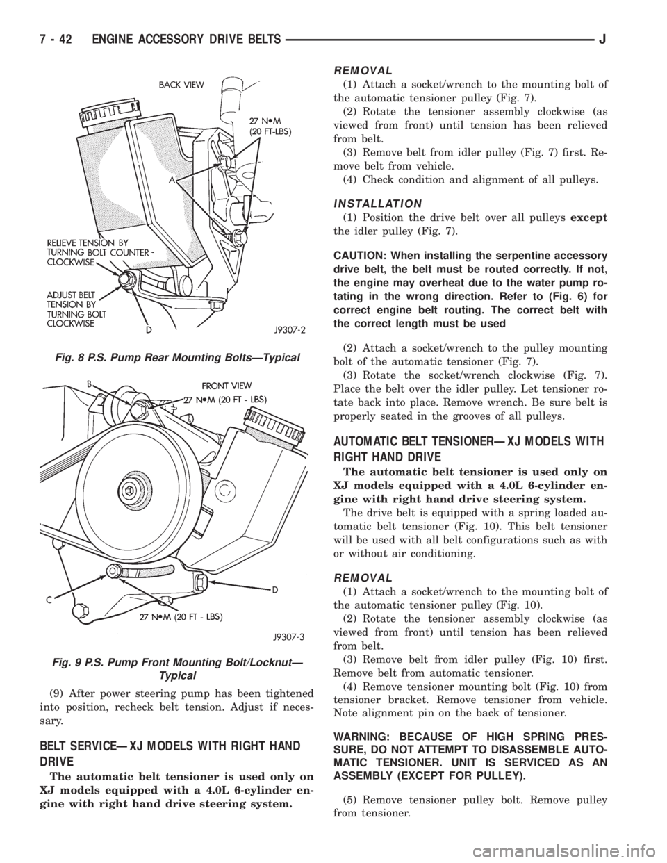
(9) After power steering pump has been tightened
into position, recheck belt tension. Adjust if neces-
sary.
BELT SERVICEÐXJ MODELS WITH RIGHT HAND
DRIVE
The automatic belt tensioner is used only on
XJ models equipped with a 4.0L 6-cylinder en-
gine with right hand drive steering system.
REMOVAL
(1) Attach a socket/wrench to the mounting bolt of
the automatic tensioner pulley (Fig. 7).
(2) Rotate the tensioner assembly clockwise (as
viewed from front) until tension has been relieved
from belt.
(3) Remove belt from idler pulley (Fig. 7) first. Re-
move belt from vehicle.
(4) Check condition and alignment of all pulleys.
INSTALLATION
(1) Position the drive belt over all pulleysexcept
the idler pulley (Fig. 7).
CAUTION: When installing the serpentine accessory
drive belt, the belt must be routed correctly. If not,
the engine may overheat due to the water pump ro-
tating in the wrong direction. Refer to (Fig. 6) for
correct engine belt routing. The correct belt with
the correct length must be used
(2) Attach a socket/wrench to the pulley mounting
bolt of the automatic tensioner (Fig. 7).
(3) Rotate the socket/wrench clockwise (Fig. 7).
Place the belt over the idler pulley. Let tensioner ro-
tate back into place. Remove wrench. Be sure belt is
properly seated in the grooves of all pulleys.
AUTOMATIC BELT TENSIONERÐXJ MODELS WITH
RIGHT HAND DRIVE
The automatic belt tensioner is used only on
XJ models equipped with a 4.0L 6-cylinder en-
gine with right hand drive steering system.
The drive belt is equipped with a spring loaded au-
tomatic belt tensioner (Fig. 10). This belt tensioner
will be used with all belt configurations such as with
or without air conditioning.
REMOVAL
(1) Attach a socket/wrench to the mounting bolt of
the automatic tensioner pulley (Fig. 10).
(2) Rotate the tensioner assembly clockwise (as
viewed from front) until tension has been relieved
from belt.
(3) Remove belt from idler pulley (Fig. 10) first.
Remove belt from automatic tensioner.
(4) Remove tensioner mounting bolt (Fig. 10) from
tensioner bracket. Remove tensioner from vehicle.
Note alignment pin on the back of tensioner.
WARNING: BECAUSE OF HIGH SPRING PRES-
SURE, DO NOT ATTEMPT TO DISASSEMBLE AUTO-
MATIC TENSIONER. UNIT IS SERVICED AS AN
ASSEMBLY (EXCEPT FOR PULLEY).
(5) Remove tensioner pulley bolt. Remove pulley
from tensioner.
Fig. 8 P.S. Pump Rear Mounting BoltsÐTypical
Fig. 9 P.S. Pump Front Mounting Bolt/LocknutÐ
Typical
7 - 42 ENGINE ACCESSORY DRIVE BELTSJ
Page 296 of 2158

STARTING SYSTEM
GENERAL INFORMATION
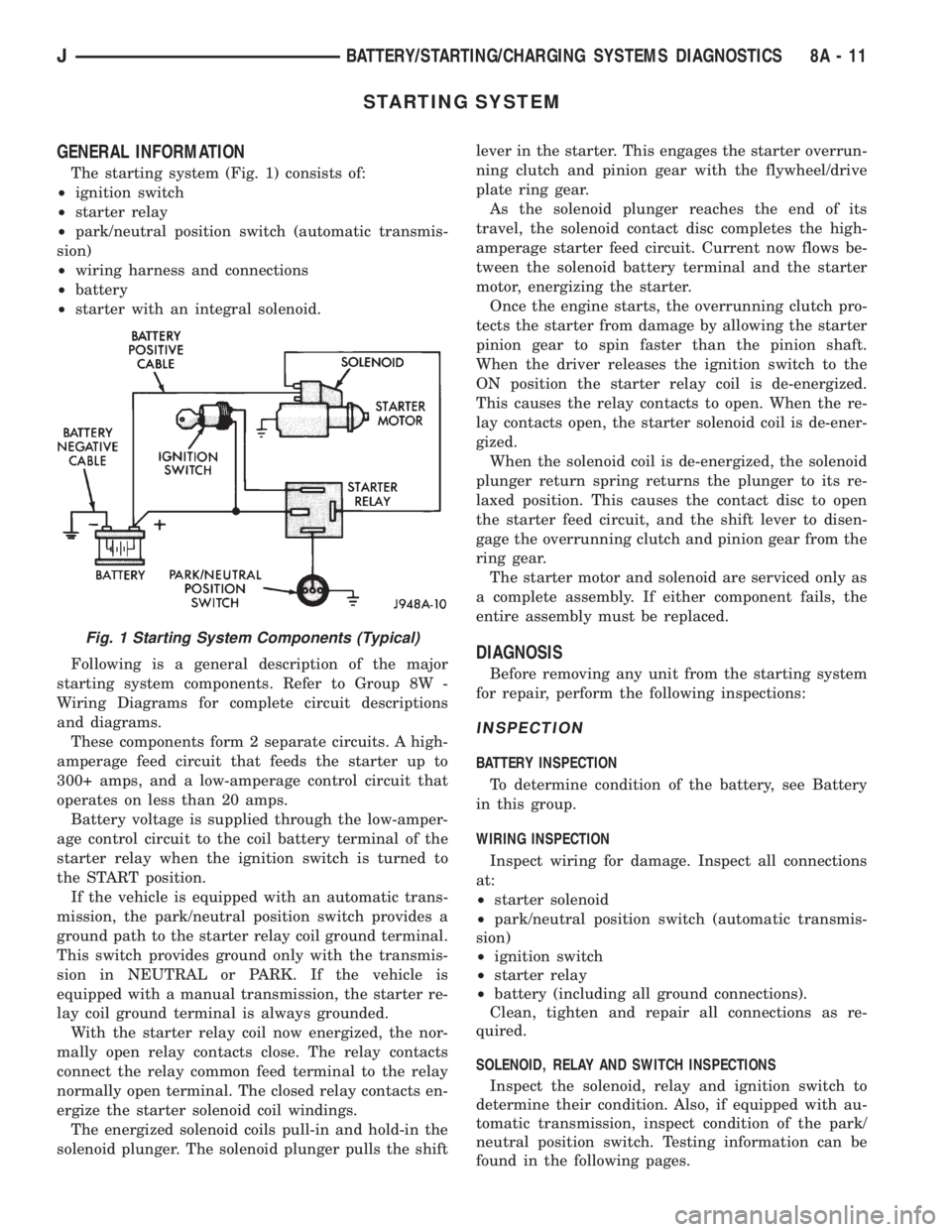
The starting system (Fig. 1) consists of:
²ignition switch
²starter relay
²park/neutral position switch (automatic transmis-
sion)
²wiring harness and connections
²battery
²starter with an integral solenoid.
Following is a general description of the major
starting system components. Refer to Group 8W -
Wiring Diagrams for complete circuit descriptions
and diagrams.
These components form 2 separate circuits. A high-
amperage feed circuit that feeds the starter up to
300+ amps, and a low-amperage control circuit that
operates on less than 20 amps.
Battery voltage is supplied through the low-amper-
age control circuit to the coil battery terminal of the
starter relay when the ignition switch is turned to
the START position.
If the vehicle is equipped with an automatic trans-
mission, the park/neutral position switch provides a
ground path to the starter relay coil ground terminal.
This switch provides ground only with the transmis-
sion in NEUTRAL or PARK. If the vehicle is
equipped with a manual transmission, the starter re-
lay coil ground terminal is always grounded.
With the starter relay coil now energized, the nor-
mally open relay contacts close. The relay contacts
connect the relay common feed terminal to the relay
normally open terminal. The closed relay contacts en-
ergize the starter solenoid coil windings.
The energized solenoid coils pull-in and hold-in the
solenoid plunger. The solenoid plunger pulls the shiftlever in the starter. This engages the starter overrun-
ning clutch and pinion gear with the flywheel/drive
plate ring gear.
As the solenoid plunger reaches the end of its
travel, the solenoid contact disc completes the high-
amperage starter feed circuit. Current now flows be-
tween the solenoid battery terminal and the starter
motor, energizing the starter.
Once the engine starts, the overrunning clutch pro-
tects the starter from damage by allowing the starter
pinion gear to spin faster than the pinion shaft.
When the driver releases the ignition switch to the
ON position the starter relay coil is de-energized.
This causes the relay contacts to open. When the re-
lay contacts open, the starter solenoid coil is de-ener-
gized.
When the solenoid coil is de-energized, the solenoid
plunger return spring returns the plunger to its re-
laxed position. This causes the contact disc to open
the starter feed circuit, and the shift lever to disen-
gage the overrunning clutch and pinion gear from the
ring gear.
The starter motor and solenoid are serviced only as
a complete assembly. If either component fails, the
entire assembly must be replaced.
DIAGNOSIS
Before removing any unit from the starting system
for repair, perform the following inspections:
INSPECTION
BATTERY INSPECTION
To determine condition of the battery, see Battery
in this group.
WIRING INSPECTION
Inspect wiring for damage. Inspect all connections
at:
²starter solenoid
²park/neutral position switch (automatic transmis-
sion)
²ignition switch
²starter relay
²battery (including all ground connections).
Clean, tighten and repair all connections as re-
quired.
SOLENOID, RELAY AND SWITCH INSPECTIONS
Inspect the solenoid, relay and ignition switch to
determine their condition. Also, if equipped with au-
tomatic transmission, inspect condition of the park/
neutral position switch. Testing information can be
found in the following pages.
Fig. 1 Starting System Components (Typical)
JBATTERY/STARTING/CHARGING SYSTEMS DIAGNOSTICS 8A - 11
Page 303 of 2158

²accessories being left on with the engine not run-
ning
²a faulty or improperly adjusted switch that allows
a lamp to stay on (see Ignition-Off Draw, in this
group).
INSPECTION
(1) Inspect condition of battery cable terminals,
battery posts, connections at engine block, starter so-
lenoid and relay. They should be clean and tight. Re-
pair as required.
(2) Inspect all fuses in the fuseblock module and
Power Distribution Center (PDC) for tightness in re-
ceptacles. They should be properly installed and
tight. Repair or replace as required.
(3) Inspect the electrolyte level in the battery. If
cell caps are removable, add water if required. If cell
caps are not removable, replace battery if electrolyte
level is low.
(4) Inspect generator mounting bolts for tightness.
Replace or tighten bolts, if required. Refer to Group
8B - Battery/Starter/Generator Service for torque
specifications.
(5) Inspect generator drive belt condition and ten-
sion. Tighten or replace belt as required. Refer to
Belt Tension Specifications in Group 7 - Cooling Sys-
tem.
(6) Inspect connections at generator field, battery
output, and ground terminals. Also check ground con-
nection at engine. They should all be clean and tight.
Repair as required.
OUTPUT WIRE RESISTANCE TEST
This test will show the amount of voltage drop
across the generator output wire, from the generator
battery terminal to the battery positive post.
PREPARATION
(1) Before starting test make sure vehicle has a
fully-charged battery. See Battery in this group for
more information.
(2) Turn ignition switch to OFF.
(3) Disconnect negative cable from battery.
(4) Disconnect generator output wire from genera-
tor battery output terminal.
(5) Connect a 0-150 ampere scale DC ammeter
(Fig. 2). Install in series between generator battery
output terminal and disconnected generator output
wire. Connect positive lead to generator battery out-
put terminal and negative lead to disconnected gen-
erator output wire.
(6) Connect positive lead of a test voltmeter (range
0-18 volts minimum) to disconnected generator out-
put wire. Connect negative lead of test voltmeter to
battery positive cable at positive post.
(7) Connect one end of a jumper wire to ground
and with other end probe green K20 field wire at
back of generator (Fig. 2). This will generate a DTC.CAUTION: Do not connect green/orange A142 field
wire to ground. Refer to Group 8W - Wiring Dia-
grams for more information.
(8) Connect an engine tachometer, then connect
battery negative cable to battery.
(9) Connect a variable carbon pile rheostat be-
tween battery terminals. Be sure carbon pile is in
OPEN or OFF position before connecting leads. See
Load Test in this group for instructions.
TEST
(1) Start engine. Immediately after starting, re-
duce engine speed to idle.
(2) Adjust engine speed and carbon pile to main-
tain 20 amperes flowing in circuit. Observe voltmeter
reading. Voltmeter reading should not exceed 0.5
volts.
RESULTS
If a higher voltage drop is indicated, inspect, clean
and tighten all connections. This includes any con-
nection between generator battery output terminal
and battery positive post. A voltage drop test may be
performed at each connection to locate the connection
with excessive resistance. If resistance tests satisfac-
torily, reduce engine speed, turn OFF carbon pile and
turn OFF ignition switch.
(1) Disconnect negative cable from battery.
(2) Remove test ammeter, voltmeter, carbon pile,
and tachometer.
(3) Remove jumper wire.
(4) Connect generator output wire to generator
battery output terminal. Tighten nut to 8.561.5 Nzm
(75615 in. lbs.).
(5) Connect negative cable to battery.
(6) Use DRB scan tool to erase DTC.
CURRENT OUTPUT TEST
The generator current output test determines
whether generator can deliver its rated current out-
put.
PREPARATION
(1) Before starting test make sure vehicle has a
fully-charged battery. See Battery in this group for
more information.
(2) Disconnect negative cable from battery.
(3) Disconnect generator output wire at the gener-
ator battery output terminal.
(4) Connect a 0-150 ampere scale DC ammeter
(Fig. 3). Install in series between generator battery
output terminal and disconnected generator output
wire. Connect positive lead to generator battery out-
put terminal and negative lead to disconnected gen-
erator output wire.
8A - 18 BATTERY/STARTING/CHARGING SYSTEMS DIAGNOSTICSJ
Page 317 of 2158

OVERHEAD CONSOLE
CONTENTS
page page
DIAGNOSIS............................. 2
GENERAL INFORMATION.................. 1SERVICE PROCEDURES................... 5
GENERAL INFORMATION
An overhead console featuring an electronic com-
pass and thermometer is an available option for XJ
(Cherokee) models. Following are general descrip-
tions of major components used in the overhead con-
sole. Refer to Group 8W - Wiring Diagrams for
complete circuit descriptions and diagrams.
COMPASS
The compass will display the direction in which the
vehicle is pointed using the eight major compass
headings (Examples: north is N, northeast is NE). It
does not display the headings in actual degrees. The
display is turned on or off using the COMP/TEMP
button to the left of the display.
The self-calibrating compass unit requires no ad-
justing in normal use. The only calibration that may
prove necessary is to drive the vehicle in 3 complete
circles, on level ground, in not less than 48 seconds.
This will reorient the unit to its vehicle.
The unit also will compensate for magnetism the
body of the vehicle may acquire during normal use.
However, avoid placing anything magnetic directly on
the roof of the vehicle. Magnetic mounts for an an-
tenna, a repair order hat or a funeral procession flag
can exceed the compensating ability of the compass
unit if placed on the roof panel. Magnetic bit drivers
used on the fasteners that hold the assembly to the
roof header can also affect compass operation.
If the vehicle roof should become magnetized, the
demagnetizing and calibration procedures may be re-
quired to restore proper operation.
THERMOMETER
The thermometer displays the outside ambient
temperature. The temperature displayed can be
changed from Fahrenheit to Celsius using the US/
METRIC button. The displayed temperature is not
an instant reading of conditions, but an average tem-
perature. It may take the unit several minutes to re-
act to a major temperature change such as driving
out of a heated garage into winter temperatures.
When the ignition switch is turned OFF, the lastdisplayed temperature reading stays in memory.
When the ignition switch is turned ON again, the
thermometer will display the memory temperature
for one minute; then update the display to the cur-
rent average temperature reading within five min-
utes.
READING AND COURTESY LAMPS
All reading and courtesy lamps in the overhead
console are activated by the door jamb switches.
When all doors and the liftgate are closed, the lamps
can be individually activated by depressing the corre-
sponding lens. When a door and/or the liftgate is
open, depressing the lamp lens switches will not turn
the lamps off. Refer to Group 8L - Lamps, for diag-
nosis and service of these lamps.
KEYLESS ENTRY RECEIVER
The overhead console houses the keyless entry re-
ceiver. Refer to Group 8P - Power Locks, for diagno-
sis and service of this component.
REMOTE GARAGE DOOR OPENER STORAGE
A compartment in the overhead console is designed
to hold most remote garage door opener transmitters.
The transmitter is mounted within the compartment
with an adhesive-backed hook and loop fastener
patch. Then one to three pegs are selected and
mounted on a post on the inside of the storage com-
partment door. The pegs may be stacked, if neces-
sary. The peg(s) selected must be long enough to
activate the button of the transmitter each time the
storage compartment door is depressed.
SUNGLASSES STORAGE
A flocked storage compartment for sunglasses is in-
cluded in the overhead console. This compartment
features a push/push-type latch and a viscous damp-
ening system for a fluid opening motion.
JOVERHEAD CONSOLE 8C - 1
Page 329 of 2158

On the 4.0L 6-cylinder engine, the ignition coil is
mounted to a bracket on the side of the engine (to
the front of the distributor) (Fig. 11).
For component testing, refer to the Diagnostics/Ser-
vice Procedures section of this group.
For removal and installation of this component, re-
fer to the Component Removal/Installation section of
this group.
ENGINE COOLANT TEMPERATURE SENSOR
For an operational description, diagnosis and re-
moval/installation procedures, refer to Group 14,
Fuel System.
INTAKE MANIFOLD AIR TEMPERATURE SENSOR
For an operational description, diagnosis or remov-
al/ installation procedures, refer to Group 14, Fuel
Systems.
MANIFOLD ABSOLUTE PRESSURE (MAP) SENSOR
For an operational description, diagnosis and re-
moval/installation procedures, refer to Group 14,
Fuel System.
POWERTRAIN CONTROL MODULE (PCM)
The PCM was formerly referred to as the SBEC or
engine controller. On XJ models, the PCM is located
in the engine compartment next to the air cleaner
(Fig. 12). On YJ models, the PCM is located in the
engine compartment behind the windshield washer
fluid reservoir (Fig. 13).
The ignition system is controlled by the PCM.
Base ignition timing by rotation of distributor
is not adjustable.The PCM opens and closes the ig-
nition coil ground circuit to operate the ignition coil.
This is done to adjust ignition timing, both initial
(base) and advance, for changing engine operating
conditions.The amount of electronic spark advance provided
by the PCM is determined by five input factors: En-
gine coolant temperature, engine rpm, intake mani-
fold air temperature, intake manifold absolute
pressure and throttle position.
For removal and installation of this component, re-
fer to the Component Removal/Installation section of
this group.
For PCM diagnostics, refer to the appropriate Pow-
ertrain Diagnostic Procedures service manual for op-
eration of the DRB scan tool.
THROTTLE POSITION SENSOR
For an operational description, diagnosis and re-
moval/installation procedures, refer to Group 14,
Fuel System.
OXYGEN (O2S) SENSOR
For an operational description, diagnosis and re-
moval/installation procedures, refer to Group 14,
Fuel System.
Fig. 11 Ignition CoilÐTypical
Fig. 12 PCM LocationÐXJ Models
Fig. 13 PCM LocationÐYJ Models
JIGNITION SYSTEMS 8D - 5
Page 335 of 2158

(4) Crank the engine for 5 seconds while monitor-
ing the voltage at the coil positive terminal:
²If the voltage remains near zero during the entire
period of cranking, refer to On-Board Diagnostics in
Group 14, Fuel Systems. Check the powertrain con-
trol module (PCM) and auto shutdown relay.
²If voltage is at or near battery voltage and drops
to zero after 1-2 seconds of cranking, check the cam-
shaft position sensor-to-PCM circuit. Refer to On-
Board Diagnostics in Group 14, Fuel Systems.
²If voltage remains at or near battery voltage dur-
ing the entire 5 seconds, turn the key off. Remove
the 60-way connector (Fig. 15) from the PCM. Check
60-way connector for any spread terminals.
(5) Remove test lead from the coil positive termi-
nal. Connect an 18 gauge jumper wire between the
battery positive terminal and the coil positive termi-
nal.
(6) Make the special jumper shown in figure 16.
Using the jumper,momentarilyground pin/cavity
number 19 of the PCM 60-way connector. A spark
should be generated at the coil cable when the
ground is removed.
(7) If spark is generated, replace the powertrain
control module (PCM).
(8) If spark is not seen, use the special jumper to
ground the coil negative terminal directly.
(9) If spark is produced, repair wiring harness for
an open condition.
(10) If spark is not produced, replace the ignition
coil.IGNITION TIMING
Base (initial) ignition timing is NOT adjust-
able on any of the 2.5L 4-cylinder or 4.0L 6-cyl-
inder engines. Do not attempt to adjust ignition
timing by rotating the distributor.
Do not attempt to modify the distributor
housing to get distributor rotation. Distributor
position will have no effect on ignition timing.
All ignition timing functions are controlled by the
powertrain control module (PCM). Refer to On-Board
Diagnostics in the Multi-Port Fuel InjectionÐGen-
eral Diagnosis section of Group 14, Fuel Systems for
more information. Also refer to the appropriate Pow-
ertrain Diagnostics Procedures service manual for op-
eration of the DRB Scan Tool.
INTAKE MANIFOLD AIR TEMPERATURE SENSOR
TEST
For an operational description, diagnosis or remov-
al/ installation procedures, refer to Group 14, Fuel
Systems.
MANIFOLD ABSOLUTE PRESSURE (MAP) SENSOR
TEST
For an operational description, diagnosis and re-
moval/installation procedures, refer to Group 14,
Fuel System.
POWERTRAIN CONTROL MODULE (PCM)
The PCM (formerly referred to as the SBEC or en-
gine controller) is located in the engine compartment
behind the windshield washer fluid tank on YJ mod-
els (Fig. 17). It is located in the engine compartment
next to the air cleaner on XJ models (Fig. 18).
The ignition system is controlled by the PCM.
For removal and installation of this component, re-
fer to the Component Removal/Installation section of
this group.
Fig. 15 PCM 60-Way Connector
Fig. 16 Special Jumper Ground-to-Coil Negative
Terminal
Fig. 17 PCM LocationÐYJ Models
JIGNITION SYSTEMS 8D - 11
Page 336 of 2158

For diagnostics, refer to the appropriate Powertrain
Diagnostic Procedures service manual for operation
of the DRB scan tool.
SPARK PLUGS
For spark plug removal, cleaning, gap adjustment
and installation, refer to the Component Removal/In-
stallation section of this group.
Faulty carbon and/or gas fouled plugs generally
cause hard starting, but they will clean up at higher
engine speeds. Faulty plugs can be identified in a
number of ways: poor fuel economy, power loss, de-
crease in engine speed, hard starting and, in general,
poor engine performance.
Remove the spark plugs and examine them for
burned electrodes and fouled, cracked or broken por-
celain insulators. For identification, keep plugs ar-
ranged in the order in which they were removed from
the engine. An isolated plug displaying an abnormal
condition indicates that a problem exists in the cor-
responding cylinder. Replace spark plugs at the inter-
vals recommended in the maintenance chart in
Group 0, Lubrication and Maintenance.
Spark plugs that have low mileage may be cleaned
and reused if not otherwise defective. Refer to the
following Spark Plug Condition section of this group.
CONDITION
NORMAL OPERATING
The few deposits present on the spark plug will
probably be light tan or slightly gray in color. This is
evident with most grades of commercial gasoline
(Fig. 19). There will not be evidence of electrode
burning. Gap growth will not average more than ap-
proximately 0.025 mm (.001 in) per 1600 km (1000
miles) of operation. Spark plugs that have normal
wear can usually be cleaned, have the electrodes
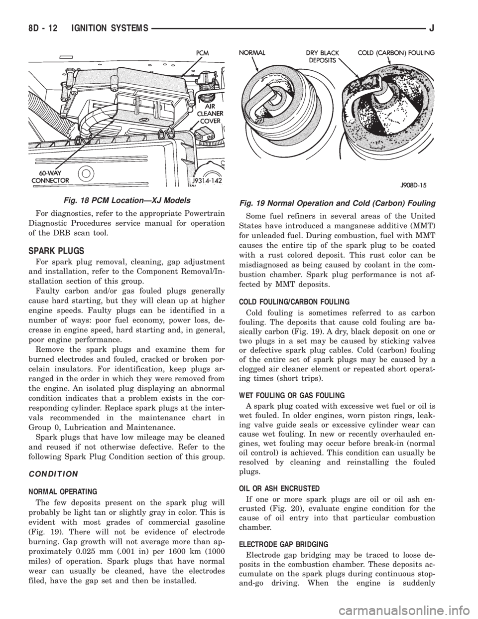
filed, have the gap set and then be installed.Some fuel refiners in several areas of the United
States have introduced a manganese additive (MMT)
for unleaded fuel. During combustion, fuel with MMT
causes the entire tip of the spark plug to be coated
with a rust colored deposit. This rust color can be
misdiagnosed as being caused by coolant in the com-
bustion chamber. Spark plug performance is not af-
fected by MMT deposits.
COLD FOULING/CARBON FOULING
Cold fouling is sometimes referred to as carbon
fouling. The deposits that cause cold fouling are ba-
sically carbon (Fig. 19). A dry, black deposit on one or
two plugs in a set may be caused by sticking valves
or defective spark plug cables. Cold (carbon) fouling
of the entire set of spark plugs may be caused by a
clogged air cleaner element or repeated short operat-
ing times (short trips).
WET FOULING OR GAS FOULING
A spark plug coated with excessive wet fuel or oil is
wet fouled. In older engines, worn piston rings, leak-
ing valve guide seals or excessive cylinder wear can
cause wet fouling. In new or recently overhauled en-
gines, wet fouling may occur before break-in (normal
oil control) is achieved. This condition can usually be
resolved by cleaning and reinstalling the fouled
plugs.
OIL OR ASH ENCRUSTED
If one or more spark plugs are oil or oil ash en-
crusted (Fig. 20), evaluate engine condition for the
cause of oil entry into that particular combustion
chamber.
ELECTRODE GAP BRIDGING
Electrode gap bridging may be traced to loose de-
posits in the combustion chamber. These deposits ac-
cumulate on the spark plugs during continuous stop-
and-go driving. When the engine is suddenly
Fig. 18 PCM LocationÐXJ ModelsFig. 19 Normal Operation and Cold (Carbon) Fouling
8D - 12 IGNITION SYSTEMSJ
Page 341 of 2158

COMPONENT REMOVAL/INSTALLATION
INDEX
page page
Automatic Shutdown (ASD) Relay............. 17
Camshaft Position Sensor................... 17
Crankshaft Position Sensor.................. 17
Distributor............................... 19
Engine Coolant Temperature Sensor........... 19
General Information....................... 17
Ignition Coil............................. 22Intake Manifold Air Temperature Sensor......... 23
Manifold Absolute Pressure (MAP) Sensor....... 23
Oxygen (O2S) Sensor...................... 23
Powertrain Control Module (PCM)............. 23
Spark Plug Secondary Cables................ 24
Spark Plugs............................. 23
Throttle Position Sensor (TPS)............... 25
GENERAL INFORMATION
This section of the group, Component Removal/In-
stallation, will discuss the removal and installation
of ignition system components.
For basic ignition system diagnostics and service
adjustments, refer to the Diagnostics/Service Proce-
dures section of this group.
For system operation and component identification,
refer to the Component Identification/System Opera-
tion section of this group.
AUTOMATIC SHUTDOWN (ASD) RELAY
The ASD relay is installed in the power distribu-
tion center (PDC) (Figs. 1 or 2). Relay location is
printed on the PDC cover.
REMOVAL
(1) Remove the PDC cover.
(2) Remove the relay by lifting straight up.
INSTALLATION
(1) Check the condition of relay wire terminals at
PDC before installing relay. Repair as necessary.
(2) Push the relay into the connector.
(3) Install the relay cover.
CAMSHAFT POSITION SENSOR
The camshaft position sensor is located in the dis-
tributor (Fig. 3).
REMOVAL
Distributor removal is not necessary to remove
camshaft position sensor.
(1) Disconnect negative battery cable at battery.
(2) Remove distributor cap from distributor (two
screws).
(3) Disconnect camshaft position sensor wiring
harness from main engine wiring harness.
(4) Remove distributor rotor from distributor shaft.
(5) Lift the camshaft position sensor assembly
from the distributor housing (Fig. 3).
INSTALLATION
(1) Install camshaft position sensor to distributor.
Align sensor into notch on distributor housing.
(2) Connect wiring harness.
(3) Install rotor.
(4) Install distributor cap. Tighten mounting
screws.
CRANKSHAFT POSITION SENSOR
The crankshaft position sensor is mounted in the
Fig. 1 PDCÐXJ Models
Fig. 2 PDCÐYJ Models
JIGNITION SYSTEMS 8D - 17