1995 JEEP XJ air condition
[x] Cancel search: air conditionPage 67 of 2158
YJ FRONT SUSPENSION
INDEX
page page
Leaf Spring.............................. 16
Leaf Spring Eye Bushing Replacement......... 17
Service Information........................ 15
Shock Absorber.......................... 16Spring and Shock Diagnosis................. 15
Stabilizer Bar............................ 15
Track Bar............................... 15
SERVICE INFORMATION
Periodic lubrication of the steering system and sus-
pension components is required. Refer to Group 0,
Lubrication And Maintenance for the service inter-
val.
CAUTION: Suspension components with rubber
bushings should be tightened with the vehicle at
normal height. It is important to have the springs
supporting the weight of the vehicle when the fas-
teners are torqued. If springs are not at their normal
ride position, vehicle ride comfort could be affected
and premature bushing wear may occur. Rubber
bushings must never be lubricated.
TRACK BAR
REMOVAL
(1) Raise and support the vehicle.
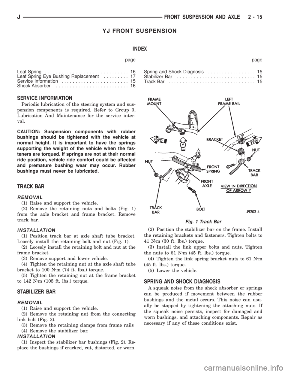
(2) Remove the retaining nuts and bolts (Fig. 1)
from the axle bracket and frame bracket. Remove
track bar.
INSTALLATION
(1) Position track bar at axle shaft tube bracket.
Loosely install the retaining bolt and nut (Fig. 1).
(2) Loosely install the retaining bolt and nut at the
frame bracket.
(3) Remove support and lower vehicle.
(4) Tighten the retaining nut at the axle shaft tube
bracket to 100 Nzm (74 ft. lbs.) torque.
(5) Tighten the retaining nut at the frame bracket
to 142 Nzm (105 ft. lbs.) torque.
STABILIZER BAR
REMOVAL
(1) Raise and support the vehicle.
(2) Remove the retaining nut from the connecting
link bolt (Fig. 2).
(3) Remove the retaining clamps from frame rails
(4) Remove the stabilizer bar.
INSTALLATION
(1) Inspect the stabilizer bar bushings (Fig. 2). Re-
place the bushings if cracked, cut, distorted, or worn.(2) Position the stabilizer bar on the frame. Install
the retaining brackets and fasteners. Tighten bolts to
41 Nzm (30 ft. lbs.) torque.
(3) Install the link upper bolts and nuts. Tighten
the nuts to 61 Nzm (45 ft. lbs.) torque.
(4) Tighten the link spring bracket nuts to 61 Nzm
(45 ft. lbs.) torque.
(5) Lower the vehicle.
SPRING AND SHOCK DIAGNOSIS
A squeak noise from the shock absorber or springs
can be produced if movement between the rubber
bushings and the metal occurs. This noise can usu-
ally be stopped by tightening the attaching nuts. If
the squeak noise persists, inspect for damaged and
worn bushings, and attaching components. Repair as
necessary if any of these conditions exist.
Fig. 1 Track Bar
JFRONT SUSPENSION AND AXLE 2 - 15
Page 70 of 2158

AXLE NOISE/VIBRATION DIAGNOSIS
INDEX
page page
Driveline Snap........................... 19
Gear and Bearing Noise.................... 18
General Information....................... 18Low Speed Knock......................... 19
Vibration................................ 19
GENERAL INFORMATION
Axle bearing problem conditions are usually caused
by:
²Insufficient or incorrect lubricant
²Foreign matter/water contamination
²Incorrect bearing preload torque adjustment
²Incorrect backlash (to tight)
When serviced, the bearings must be cleaned thor-
oughly. They should be dried with lint-free shop tow-
els.Never dry bearings with compressed air.
This will overheat them and brinell the bearing
surfaces. This will result in noisy operation af-
ter repair.
Axle gear problem conditions are usually the result
of:
²Insufficient lubrication
²Incorrect or contaminated lubricant
²Overloading (excessive engine torque) or exceeding
vehicle weight capacity
²Incorrect clearance or backlash adjustment
Insufficient lubrication is usually the result of a
housing cover leak. It can also be from worn axle
shaft or pinion gear seals. Check for cracks or porous
areas in the housing or tubes.
Using the wrong lubricant will cause overheating
and gear failure. Gear tooth cracking and bearing
spalling are indicators of this.
Axle component breakage is most often the result
of:
²Severe overloading
²Insufficient lubricant
²Incorrect lubricant
²Improperly tightened components
Overloading occurs when towing heavier than rec-
ommended loads. Component breakage can occur
when the wheels are spun excessively. Incorrect lu-
bricant quantity contributes to breakage. Loose dif-
ferential components can also cause breakage.
Incorrect bearing preload or gear backlash will not
result in component breakage. Mis-adjustment will
produce enough noise to cause service repair before a
failure occurs. If a mis-adjustment condition is not
corrected, component failure can result.
Excessive bearing preload may not be noisy. This
condition will cause high temperature which can re-
sult in bearing failure.
GEAR AND BEARING NOISE
GEAR NOISE
Axle gear noise can be caused by insufficient lubri-
cant. Incorrect backlash, tooth contact, or worn/dam-
aged gears can cause noise.
Gear noise usually happens at a specific speed
range. The range is 30 to 40 mph, or above 50 mph.
The noise can also occur during a specific type of
driving condition. These conditions are acceleration,
deceleration, coast, or constant load.
When road testing, accelerate the vehicle to the
speed range where the noise is the greatest. Shift
out-of-gear and coast through the peak-noise range.
If the noise stops or changes greatly, check for insuf-
ficient lubricant. Incorrect ring gear backlash, or
gear damage can cause noise changes.
Differential side and pinion gears can be checked
by turning the vehicle. They usually do not cause
noise in straight-ahead driving. These gears are
loaded during vehicle turns. If noise does occur dur-
ing vehicle turns, the side or pinion gears could be
worn or damaged. A worn pinion gear mate shaft can
also cause a snapping or a knocking noise.
BEARING NOISE
The axle shaft, differential and pinion gear bear-
ings can all produce noise when worn or damaged.
Bearing noise can be either a whining, or a growling
sound.
Pinion gear bearings have a constant-pitch noise.
This noise changes only with vehicle speed. Pinion
bearing noise will be higher because it rotates at a
faster rate. Drive the vehicle and load the differen-
tial. If bearing noise occurs the pinion rear bearing is
the source of the noise. If the bearing noise is heard
during a coast, front bearing is the source.
Worn, damaged differential bearings usually pro-
duce a low pitch noise. Differential bearing noise is
similar to pinion bearing. The pitch of differential
bearing noise is also constant and varies only with
vehicle speed.
2 - 18 FRONT SUSPENSION AND AXLEJ
Page 110 of 2158
AXLE NOISE/VIBRATION DIAGNOSIS
INDEX
page page
Driveline Snap........................... 10
Gear and Bearing Noise..................... 9
General Information........................ 9
Limited Slip Differential..................... 10Low Speed Knock......................... 10
Rear Axle Alignment....................... 10
Vibration................................ 10
GENERAL INFORMATION
Axle bearing problem conditions are usually caused
by:
²Insufficient or incorrect lubricant
²Foreign matter/water contamination
²Incorrect bearing preload torque adjustment
²Incorrect backlash (to tight)
When serviced, the bearings must be cleaned thor-
oughly. They should be dried with lint-free shop tow-
els.Never dry bearings with compressed air.
This will overheat them and brinell the bearing
surfaces. This will result in noisy operation af-
ter repair.
Axle gear problem conditions are usually the result of:
²Insufficient lubrication
²Incorrect or contaminated lubricant
²Overloading (excessive engine torque) or exceeding
vehicle weight capacity
²Incorrect clearance or backlash adjustment
Insufficient lubrication is usually the result of a
housing cover leak. It can also be from worn axle
shaft or pinion gear seals. Check for cracks or porous
areas in the housing or tubes.
Using the wrong lubricant will cause overheating
and gear failure. Gear tooth cracking and bearing
spalling are indicators of this.
Axle component breakage is most often the result of:
²Severe overloading
²Insufficient lubricant
²Incorrect lubricant
²Improperly tightened components
Overloading occurs when towing heavier than rec-
ommended loads. Component breakage can occur
when the wheels are spun excessively. Incorrect lu-
bricant quantity contributes to breakage. Loose dif-
ferential components can also cause breakage.
Incorrect bearing preload or gear backlash will not
result in component breakage. Mis-adjustment will
produce enough noise to cause service repair before a
failure occurs. If a mis-adjustment condition is not
corrected, component failure can result.
Excessive bearing preload may not be noisy. This
condition will cause high temperature which can re-
sult in bearing failure.
GEAR AND BEARING NOISE
GEAR NOISE
Axle gear noise can be caused by insufficient lubri-
cant. Incorrect backlash, tooth contact, or worn/dam-
aged gears can cause noise.
Gear noise usually happens at a specific speed
range. The range is 30 to 40 mph, or above 50 mph.
The noise can also occur during a specific type of
driving condition. These conditions are acceleration,
deceleration, coast, or constant load.
When road testing, accelerate the vehicle to the
speed range where the noise is the greatest. Shift
out-of-gear and coast through the peak-noise range.
If the noise stops or changes greatly, check for insuf-
ficient lubricant. Incorrect ring gear backlash, or
gear damage can cause noise changes.
Differential side and pinion gears can be checked
by turning the vehicle. They usually do not cause
noise in straight-ahead driving. These gears are
loaded during vehicle turns. If noise does occur dur-
ing vehicle turns, the side or pinion gears could be
worn or damaged. A worn pinion gear mate shaft can
also cause a snapping or a knocking noise.
BEARING NOISE
The axle shaft, differential and pinion gear bear-
ings can all produce noise when worn or damaged.
Bearing noise can be either a whining, or a growling
sound.
Pinion gear bearings have a constant-pitch noise.
This noise changes only with vehicle speed. Pinion
bearing noise will be higher because it rotates at a
faster rate. Drive the vehicle and load the differen-
tial. If bearing noise occurs the pinion rear bearing is
the source of the noise. If the bearing noise is heard
during a coast, front bearing is the source.
Worn, damaged differential bearings usually pro-
duce a low pitch noise. Differential bearing noise is
similar to pinion bearing. The pitch of differential
bearing noise is also constant and varies only with
vehicle speed.
Axle shaft bearings produce noise and vibration
when worn or damaged. The noise generally changes
when the bearings are loaded. Road test the vehicle.
Turn the vehicle sharply to the left and to the right.
JREAR SUSPENSION AND AXLES 3 - 9
Page 111 of 2158
This will load the bearings and change the noise
level. Where axle bearing damage is slight, the noise
is usually not noticeable at speeds above 30 mph.
LOW SPEED KNOCK
Low speed knock is generally caused by a worn
U-joint or by worn side-gear thrust washers. A worn
pinion gear shaft bore will also cause low speed knock.
VIBRATION
Vibration at the rear of the vehicle is usually
caused by a:
²Damaged drive shaft
²Missing drive shaft balance weight
²Worn, out-of-balance wheels
²Loose wheel lug nuts
²Worn U-joint
²Loose spring U-bolts
²Loose/broken springs
²Damaged axle shaft bearings
²Loose pinion gear nut
²Excessive pinion yoke run out
²Bent axle shaft
Check for loose or damaged front-end components
or engine/transmission mounts. These components
can contribute to what appears to be a rear-end vi-
bration. Do not overlook engine accessories, brackets
and drive belts.
All driveline components should be examined be-
fore starting any repair.
Refer to Group 22, Wheels and Tires for additional
information.
DRIVELINE SNAP
A snap or clunk noise when the vehicle is shifted
into gear (or the clutch engaged), can be caused by:
²High engine idle speed
²Loose engine/transmission/transfer case mounts
²Worn U-joints
²Loose spring mounts
²Loose pinion gear nut and yoke
²Excessive ring gear backlash
²Excessive side gear\ase clearance
The source of a snap or a clunk noise can be deter-
mined with the assistance of a helper. Raise the ve-
hicle on a hoist with the wheels free to rotate.
Instruct the helper to shift the transmission into
gear. Listen for the noise, a mechanics stethoscope is
helpful in isolating the source of a noise.
REAR AXLE ALIGNMENT
MEASUREMENT
The following procedure can be used to determine
if abnormal rear tire tread wear is the result of a
bent or deformed rear axle shaft.
(1) Raise both rear wheels off the surface with a
frame contact hoist.
(2) Attach a one-inch long piece of masking tape at
the center of each tire tread for use as reference marks.
(3) Rotate the rear wheels until both reference
marks face the front of the vehicle. Measure the dis-
tance between the outside edges of the two pieces of
tape. Record this measurement as the front of tire
(FTR) measurement.
(4) Rotate the rear wheels until both reference
marks face the rear of the vehicle. Measure the dis-
tance between the outside edges of the two pieces of
tape. Record this measurement as the rear of tire
(RTR) measurement.
(5) Subtract the (RTR) measurement from the
(FTR) measurement to obtain the amount of wheel
toe. The acceptable rear wheel toe-in position is 1/16
inch (1.6 mm) to 3/16 inch (4.8 mm) toe-out.
(6) Rotate the rear wheels until the reference
marks are facing downward. Measure the distance
between the outside edges of the two pieces of tape.
Record this measurement as the bottom of tire (BTR)
measurement.
(7) Average the (FTR) and the (RTR) distance mea-
surements. Subtract the (BTR) measurement from
this average distance to obtain the camber. The ac-
ceptable amount of camber is 1/16 inch to 3/32 inch
(1.6 to 2.4 mm).
(FTR + RTR) DIVIDED BY 2 (TWO) MINUS
BTR EQUALS CAMBER
If the (BTR) distance measurement is less
than the average FTR and RTR distance mea-
surement, the camber will be positive(+).If
the (BTR) distance measurement is greater
than the average FTR and RTR distance, the
camber will be negative(-).
If the toe position or camber is not acceptable, a bent
or deformed rear axle shaft is most likely the cause.
LIMITED SLIP DIFFERENTIAL
Under normal traction conditions, engine torque is di-
vided evenly. With low-traction surfaces, engine torque
is transferred to the wheel with the most tire traction.
When diagnosing a limited-slip differential the wheel
with the least traction can continue spinning.
The most common problem is a chatter noise when
turning corners. Check for incorrect or contaminated
lubricant. Replace the gear lubricant if necessary.
²With Trac-LokŸ differentials add a container of
MOPAR Trac-Lok Lubricant.
This will correct the condition in most instances. If
the chatter persists, clutch damage could have oc-
curred.
After changing the lubricant, drive the vehicle and
make 10 to 12 slow, figure-eight turns. This maneu-
ver will pump lubricant through the clutches.
3 - 10 REAR SUSPENSION AND AXLESJ
Page 135 of 2158
INSTALLATION
(1) Examine the splines on the pinion shaft for
burrs or wear.
(2) Remove any burrs and clean the shaft.
(3) Inspect the pinion yoke for cracks, worn splines
and a worn seal contact surface. Repair or replace
the yoke as necessary.
The outer perimeter of the seal is pre-coated
with a special sealant. An additional applica-
tion of sealant is not required.
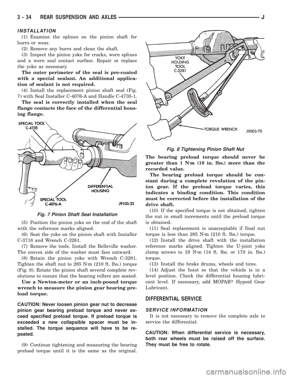
(4) Install the replacement pinion shaft seal (Fig.
7) with Seal Installer C-4076-A and Handle C-4735-1.
The seal is correctly installed when the seal
flange contacts the face of the differential hous-
ing flange.
(5) Position the pinion yoke on the end of the shaft
with the reference marks aligned.
(6) Seat the yoke on the pinion shaft with Installer
C-3718 and Wrench C-3281.
(7) Remove the tools. Install the Belleville washer.
The convex side of the washer must face outward.
(8) Retain the pinion yoke with Wrench C-3281.
Tighten the shaft nut to 285 Nzm (210 ft. lbs.) torque
(Fig. 8). Rotate the pinion shaft several complete rev-
olutions to ensure that the bearing rollers are seated.
Use a Newton-meter or an inch-pound torque
wrench to measure the pinion gear bearing pre-
load torque.
CAUTION: Never loosen pinion gear nut to decrease
pinion gear bearing preload torque and never ex-
ceed specified preload torque. If preload torque is
exceeded a new collapsible spacer must be in-
stalled. The torque sequence will have to be re-
peated.
(9) Continue tightening and measuring the bearing
preload torque until it is the same as the original.The bearing preload torque should never be
greater than 1 Nzm (10 in. lbs.) more than the
recorded value.
The bearing preload torque should be con-
stant during a complete revolution of the pin-
ion gear. If the preload torque varies, this
indicates a binding condition. This condition
must be corrected before the installation of the
drive shaft.
(10) If the specified torque is not obtained, tighten
the nut in small increments until the preload torque
is obtained.
(11) Seal replacement is unacceptable if final nut
torque is less than 285 Nzm (210 ft. lbs.) torque.
(12) Install the drive shaft with the installation
reference marks aligned. Tighten the U-joint yoke
clamp screws to 19 Nzm (14 ft. lbs. or 170 in. lbs.)
torque.
(13) Install the brake drums, wheels and tires.
(14) Adjust the hoist so that the vehicle is in a
level position. Check the differential housing lubri-
cant level. If necessary, add MOPARtHypoid Gear
Lubricant.
DIFFERENTIAL SERVICE
SERVICE INFORMATION
It is not necessary to remove the complete axle to
service the differential.
CAUTION: When differential service is necessary,
both rear wheels must be raised off the surface.
They must be free to rotate.
Fig. 7 Pinion Shaft Seal Installation
Fig. 8 Tightening Pinion Shaft Nut
3 - 34 REAR SUSPENSION AND AXLESJ
Page 155 of 2158

ABS BRAKE DIAGNOSIS
INDEX
page page
ABS Diagnostic Connector................... 3
ABS Warning Light Display................... 3
Antilock ECU and Hcu Diagnosis............... 3
DRB Scan Tool............................ 3General Information........................ 3
Normal Operating Conditions.................. 3
Wheel/Tire Size and Input Signals.............. 3
GENERAL INFORMATION
The DRB scan tool is required for ABS diagnosis.
The scan tool is used to identify ABS circuit faults.
Once a faulty circuit has been identified, refer to
the appropriate chassis/body diagnostic manual for
individual component testing.
ABS WARNING LIGHT DISPLAY
The amber antilock light illuminates at startup as
part of the system self check feature. The light illu-
minates for 2-3 seconds then goes off as part of the
normal check routine.
An ABS circuit fault is indicated when the amber
light remains on after startup, or illuminates during
vehicle operation.
Verify that a fault is actually related to the ABS
system before making repairs. For example, if the
red warning illuminates but the ABS light does not,
the problem is related to a service brake component
and not the ABS system. Or, if neither light illumi-
nates but a brake problem is noted, again, the prob-
lem is with a service brake component and not with
the ABS system.
ABS DIAGNOSTIC CONNECTOR
The ABS diagnostic connector is inside the vehicle.
The connector is the access point for the DRB scan tool.
On XJ models, the connector is located under the
instrument panel to the right of the steering column.
On some models, the connecter may be tucked under
the carpeting on the transmission tunnel. The con-
necter is a black, 6-way type.
On YJ models, the connector is under the instru-
ment panel by the the driver side kick panel. The
connecter is a black, 6 or 8-way type.
The DRB scan tool kit contains adapter cords for
both types of connecter. Use the appropriate cord for
test hookup.
DRB SCAN TOOL
ABS diagnosis is performed with the DRB scan tool.
Refer to the DRB scan tool manual for test hookup and
procedures. Diagnosis information is provided in the ap-
propriate chassis/body diagnostic manual.
WHEEL/TIRE SIZE AND INPUT SIGNALS
Antilock system operation is dependant on accurate
signals from the wheel speed sensors. Ideally, the ve-
hicle wheels and tires should all be the same size
and type. However, the Jeep ABS system is designed
to operate with a compact spare tire installed.
NORMAL OPERATING CONDITIONS
Sound Levels
The hydraulic control unit pump and solenoid valves
may produce some sound as they cycle on and off. This
is a normal condition and should not be mistaken for
faulty operation. Under most conditions, pump and so-
lenoid valve operating sounds will not be audible.
Vehicle Response In Antilock Mode
During antilock braking, the hydraulic control unit
solenoid valves cycle rapidly in response to antilock
electronic control unit signals.
The driver will experience a pulsing sensation
within the vehicle as the solenoids decrease, hold, or
increase pressure as needed. Brake pedal pulsing will
also be noted and is anormal condition.
Steering Response
A modest amount of steering input is required dur-
ing extremely high deceleration braking, or when
braking on differing traction surfaces. An example of
differing traction surfaces would be when the left
side wheels are on ice and the right side wheels are
on dry pavement.
Owner Induced Faults
Driving away with the parking brakes still applied
will cause warning light illumination. Pumping the
brake pedal will also generate a system fault and in-
terfere with ABS system operation.
ANTILOCK ECU AND HCU DIAGNOSIS
An ECU or HCU fault can only be determined
through testing with the DRB scan tool. Do not re-
place either component unless a fault is actually in-
dicated.
JABS BRAKE DIAGNOSIS 5 - 3
Page 157 of 2158
hand lever. Also note if vehicle was being operated
with parking brake partially applied (this will cause
red light to remain on).
(7) Check brake pedal operation. Verify that pedal
does not bind and has adequate free play. If pedal
lacks free play, check pedal and power booster for be-
ing loose or for bind condition. Do not road test until
condition is corrected.
(8) If components inspected look OK, road test ve-
hicle.
ROAD TESTING
(1) If amber warning light is on, problem is with
antilock system component. Refer to antilock diagno-
sis section.
(2) If red warning light is not on, proceed to step
(4).
(3) If red warning light is on, proceed as follows:
(a) See if parking brakes are applied. If brakes
are applied, release them and proceed to step (4).
(b) Note if brake pedal is abnormally low. If
pedal is definitely low and red light is still on,
check front/rear hydraulic circuits for leak.Do not
road test. Inspect and repair as needed.
(4) Check brake pedal response with transmission
in Neutral and engine running. Pedal should remain
firm under steady foot pressure. If pedal falls away,
do not road test as problem is in master cylinder, or
HCU on ABS models. If pedal holds firm, proceed to
next step.
(5) During road test, make normal and firm brake
stops in 25-35 mph range. Note faulty brake opera-
tion such as hard pedal, pull, grab, drag, noise, fade,
etc.
(6) Return to shop and inspect brake components.
Refer to inspection and diagnosis information.
COMPONENT INSPECTION
Fluid leak points and dragging brake units can
usually be located without removing any components.
The area around a leak point will be wet with fluid.
The components at a dragging brake unit (wheel,
tire, rotor) will be quite warm or hot to the touch.
Other brake problem conditions will require compo-
nent removal for proper inspection. Raise the vehicle
and remove the necessary wheels for better visual ac-
cess.
During component inspection, pay particular atten-
tion to heavily rusted/corroded brake components
(e.g. rotors, caliper pistons, brake return/holddown
springs, support plates, etc.).
Heavy accumulations of rust may be covering se-
vere damage to a brake component. It is wise to re-
move surface rust in order to accurately determine
the depth of rust penetration and damage. Light sur-
face rust is fairly normal and not a major concern (as
long as it is removed). However, heavy rust buildup,especially on high mileage vehicles may cover struc-
tural damage to such important components as
brakelines, rotors, support plates, and brake boost-
ers. Refer to the wheel brake service procedures in
this group for more information.
BRAKE WARNING LIGHT OPERATION
The red brake warning light will illuminate under
the following conditions:
²for 2-3 seconds at startup as part of normal bulb
check
²when parking brakes are applied
²low pedal caused by leak in front/rear brake hy-
draulic circuit
If the red light remains on after startup, first ver-
ify that the parking brakes are fully released. Then
check pedal action and fluid level. A red light plus
low pedal indicates the pressure differential switch
and valve have been actuated due to a system leak.
On models with ABS brakes, the amber warning
light only illuminates when an ABS malfunction has
occurred. The ABS light operates independently of
the red warning light.
PEDAL FALLS AWAY
A brake pedal that falls away under steady foot
pressure is generally the result of a system leak. The
leak point could be at a brakeline, fitting, hose,
wheel cylinder, or caliper. Internal leakage in the
master cylinder caused by worn or damaged piston
cups, may also be the problem cause.
If leakage is severe, fluid will be evident at or
around the leaking component. However internal
leakage in the master cylinder will not be physically
evident. Refer to the cylinder test procedure at the
end of this section.
LOW PEDAL
If a low pedal is experienced, pump the pedal sev-
eral times. If the pedal comes back up, worn lining
and worn rotors or drums are the most likely causes.
However, if the pedal remains low and the red warn-
ing light is on, the likely cause is a leak in the hy-
draulic system.
A decrease in master cylinder fluid level may only
be the result of normal lining wear. Fluid level will
drop somewhat as lining wear occurs. It is a result of
the outward movement of caliper and wheel cylinder
pistons to compensate for normal wear.
SPONGY PEDAL
Air in the system is the usual cause of a spongy
pedal. Brake drums machined way beyond allowable
limits (too thin), or substandard brake lines and
hoses can also cause a condition similar to a spongy
JSERVICE BRAKE DIAGNOSIS 5 - 5
Page 159 of 2158
fied. This causes pull to switch direction in favor of
the brake unit that is functioning normally.
When diagnosing a change in pull condition, re-
member that pull will return to the original direction
if the dragging brake unit is allowed to cool down
(and is not seriously damaged).
REAR BRAKE GRAB
Rear grab (or pull) is usually caused by contami-
nated lining, bent or binding shoes and support
plates, or improperly assembled components. This is
particularly true when only one rear wheel is in-
volved. However, when both rear wheels are affected,
the master cylinder could be at fault.
BRAKES DO NOT HOLD AFTER DRIVING THROUGH
DEEP WATER PUDDLES
This condition is caused by water soaked lining. If
the lining is only wet, it can be dried by driving with
the brakes lightly applied for a mile or two. However,
if the lining is both wet and dirty, disassembly and
cleaning will be necessary.
CONTAMINATED BRAKELINING
Brakelining contaminated by water is salvageable.
The lining can either be air dried or dried using heat.
In cases where brakelining is contaminated by oil,
grease, or brake fluid, the lining should be replaced.
Replacement is especially necessary when fluids/lu-
bricants have actually soaked into the lining mate-
rial. However, grease or dirt that gets onto the lining
surface (from handling) during brake repairs, can be
cleaned off. Spray the lining surface clean with Mo-
par brake cleaner.
BRAKE FLUID CONTAMINATION
There are two basic causes of brake fluid contami-
nation. The first involves allowing dirt, debris, or
other materials to enter the cylinder reservoirs when
the cover is off. The second involves adding non-rec-
ommended fluids to the cylinder reservoirs.
Brake fluid contaminated with only dirt, or debris
usually retains a normal appearance. In some cases,
the foreign material will remain suspended in the
fluid and be visible. The fluid and foreign material
can be removed from the reservoir with a suction gun
but only if the brakes have not been applied. If the
brakes are applied after contamination, system flush-
ing will be required. The master cylinder may also
have to be disassembled, cleaned and the piston seals
replaced. Foreign material lodged in the reservoir
compensator/return ports can cause brake drag by re-
stricting fluid return after brake application.
Brake fluid contaminated by a non-recommended
fluid may appear discolored, milky, oily looking, or
foamy. However, remember that brake fluid will
darken in time and occasionally be cloudy in appear-ance. These are normal conditions and should not be
mistaken for contamination.
If some type of oil has been added to the system,
the fluid will separate into distinct layers. To verify
this, drain off a sample with a clean suction gun.
Then pour the sample into a glass container and ob-
serve fluid action. If the fluid separates into distinct
layers, it is definitely contaminated.
The only real correction for contamination by non-
recommended fluid is to flush the entire hydraulic
system and replace all the seals.
BRAKE NOISE
Squeak/Squeal
Factory installed brakelining is made from as-
bestos free materials. These materials have dif-
ferent operating characteristics than previous
lining material. Under certain conditions, as-
bestos free lining may generate some squeak,
groan or chirp noise. This noise is considered
normal and does not indicate a problem. The
only time inspection is necessary, is when noise
becomes constant or when grinding, scraping
noises occur.
Constant brake squeak or squeal may be due to lin-
ings that are wet or contaminated with brake fluid,
grease, or oil. Glazed linings, rotors/drums with hard
spots, and dirt/foreign material embedded in the
brake lining also cause squeak. Loud squeak, squeal,
scraping, or grinding sounds are a sign of severely
worn brake lining. If the lining has worn completely
through in spots, metal-to-metal contact occurs.
Thump/Clunk
Thumping or clunk noises during braking are fre-
quentlynotcaused by brake components. In many
cases, such noises are caused by loose or damaged
steering, suspension, or engine components. However,
calipers that bind on the slide surfaces can generate
a thump or clunk noise. In addition, worn out, im-
properly adjusted, or improperly assembled rear
brakeshoes can also produce a thump noise.
Chatter/Shudder
Brake chatter, or shudder is usually caused by
loose or worn components, or glazed/burnt lining. Ro-
tors with hard spots can also contribute to chatter.
Additional causes of chatter are out of tolerance ro-
tors, brake lining not securely attached to the shoes,
loose wheel bearings and contaminated brake lining.
WHEEL AND TIRE PROBLEMS
Some conditions attributed to brake components
may actually be caused by a wheel or tire problem.
A damaged wheel can cause shudder, vibration and
pull. A worn or damaged tire can also cause pull.
Severely worn tires with very little tread left can
JSERVICE BRAKE DIAGNOSIS 5 - 7