Page 1752 of 2158

(4) Inspect pistons, springs and piston bores. Re-
place worn damaged pistons. Replace broken, col-
lapsed or distorted springs. Replace case if piston
bores are damaged.
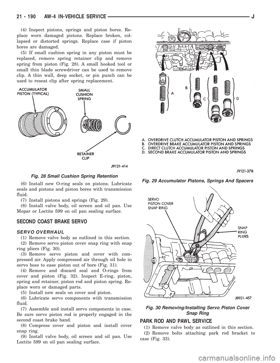
(5) If small cushion spring in any piston must be
replaced, remove spring retainer clip and remove
spring from piston (Fig. 28). A small hooked tool or
small thin blade screwdriver can be used to remove
clip. A thin wall, deep socket, or pin punch can be
used to reseat clip after spring replacement.
(6) Install new O-ring seals on pistons. Lubricate
seals and pistons and piston bores with transmission
fluid.
(7) Install pistons and springs (Fig. 29).
(8) Install valve body, oil screen and oil pan. Use
Mopar or Loctite 599 on oil pan sealing surface.
SECOND COAST BRAKE SERVO
SERVO OVERHAUL
(1) Remove valve body as outlined in this section.
(2) Remove servo piston cover snap ring with snap
ring pliers (Fig. 30).
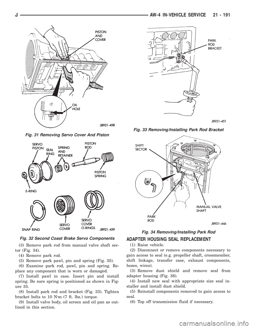
(3) Remove servo piston and cover with com-
pressed air. Apply compressed air through oil hole in
servo boss to ease piston out of bore (Fig. 31).
(4) Remove and discard seal and O-rings from
cover and piston (Fig. 32). Inspect E-ring, piston,
spring and retainer, piston rod and piston spring. Re-
place worn or damaged parts.
(5) Install new seals on cover and piston.
(6) Lubricate servo components with transmission
fluid.
(7) Assemble and install servo components in case.
Be sure servo piston rod is properly engaged in the
second coast brake band.
(8) Compress cover and piston and install cover
snap ring.
(9) Install valve body, oil screen and oil pan. Use
Loctite 599 on oil pan sealing surface.
PARK ROD AND PAWL SERVICE
(1) Remove valve body as outlined in this section.
(2) Remove bolts attaching park rod bracket to
case (Fig. 33).
Fig. 29 Accumulator Pistons, Springs And Spacers
Fig. 30 Removing/Installing Servo Piston Cover
Snap Ring
Fig. 28 Small Cushion Spring Retention
21 - 190 AW-4 IN-VEHICLE SERVICEJ
Page 1753 of 2158

(3) Remove park rod from manual valve shaft sec-
tor (Fig. 34).
(4) Remove park rod.
(5) Remove park pawl, pin and spring (Fig. 35).
(6) Examine park rod, pawl, pin and spring. Re-
place any component that is worn or damaged.
(7) Install pawl in case. Insert pin and install
spring. Be sure spring is positioned as shown in Fig-
ure 35.
(8) Install park rod and bracket (Fig. 33). Tighten
bracket bolts to 10 Nzm (7 ft. lbs.) torque.
(9) Install valve body, oil screen and oil pan as out-
lined in this section.
ADAPTER HOUSING SEAL REPLACEMENT
(1) Raise vehicle.
(2) Disconnect or remove components necessary to
gain access to seal (e.g. propeller shaft, crossmember,
shift linkage, transfer case, exhaust components,
hoses, wires).
(3) Remove dust shield and remove seal from
adapter housing (Fig. 36).
(4) Install new seal with appropriate size seal in-
staller and install dust shield.
(5) Reinstall components removed to gain access to
seal.
(6) Top off transmission fluid if necessary.
Fig. 31 Removing Servo Cover And Piston
Fig. 32 Second Coast Brake Servo Components
Fig. 33 Removing/Installing Park Rod Bracket
Fig. 34 Removing/Installing Park Rod
JAW-4 IN-VEHICLE SERVICE 21 - 191
Page 1759 of 2158

the front bumper and radiator support be removed
for access to the cooler lines and attaching bracket.
REVERSE FLUSHING MAIN AND AUXILIARY
COOLERS AND COOLER LINES
Reverse flushing the cooler and lines will prevent
sludge and particles from flowing back into the
transmission after repair. The flushing procedure ap-
plies to standard (in-radiator) coolers and auxiliary
coolers equally.
Pressure equipment is preferred for reverse flush-
ing. However, reverse flushing can be performed us-
ing hand operated equipment as described in the
following procedure.
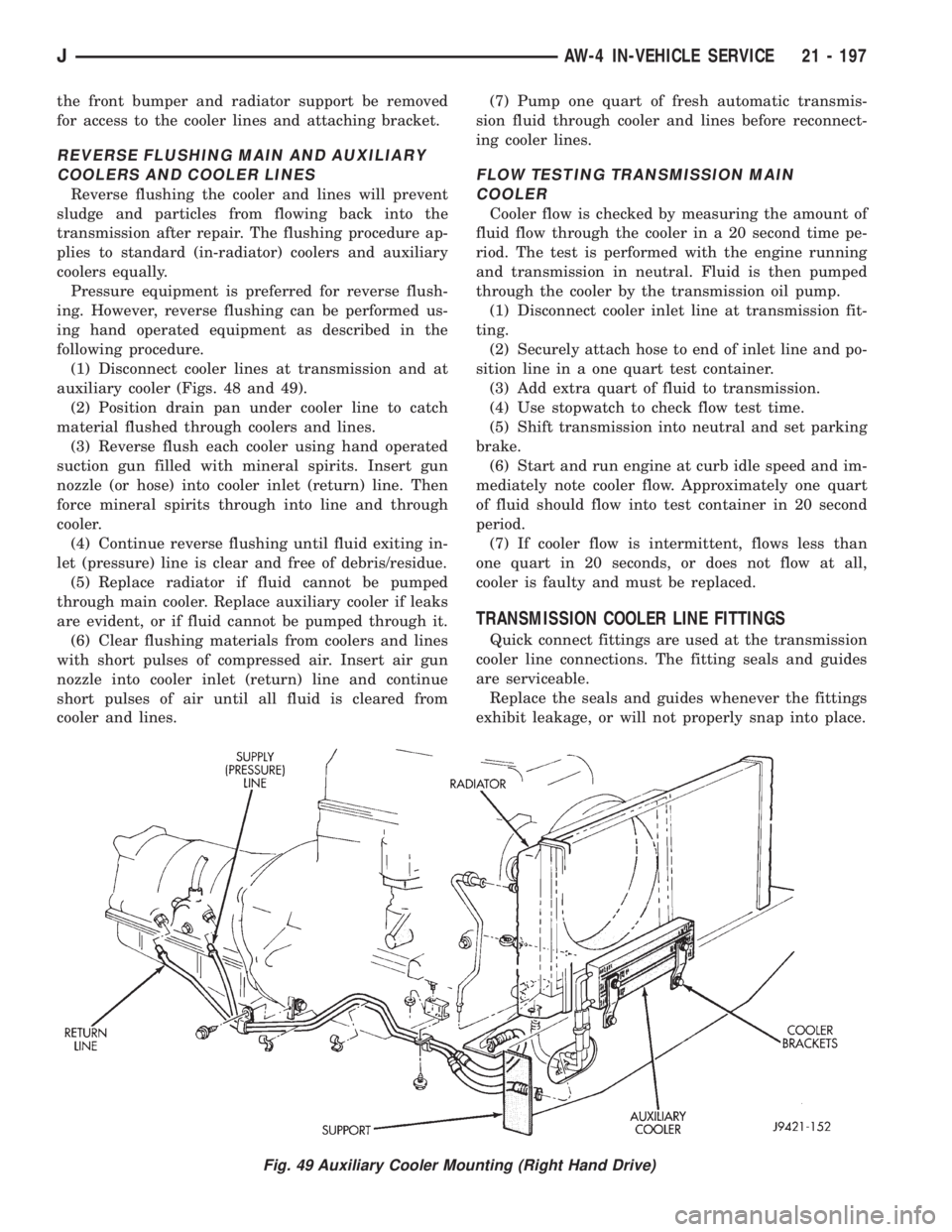
(1) Disconnect cooler lines at transmission and at
auxiliary cooler (Figs. 48 and 49).
(2) Position drain pan under cooler line to catch
material flushed through coolers and lines.
(3) Reverse flush each cooler using hand operated
suction gun filled with mineral spirits. Insert gun
nozzle (or hose) into cooler inlet (return) line. Then
force mineral spirits through into line and through
cooler.
(4) Continue reverse flushing until fluid exiting in-
let (pressure) line is clear and free of debris/residue.
(5) Replace radiator if fluid cannot be pumped
through main cooler. Replace auxiliary cooler if leaks
are evident, or if fluid cannot be pumped through it.
(6) Clear flushing materials from coolers and lines
with short pulses of compressed air. Insert air gun
nozzle into cooler inlet (return) line and continue
short pulses of air until all fluid is cleared from
cooler and lines.(7) Pump one quart of fresh automatic transmis-
sion fluid through cooler and lines before reconnect-
ing cooler lines.
FLOW TESTING TRANSMISSION MAIN
COOLER
Cooler flow is checked by measuring the amount of
fluid flow through the cooler in a 20 second time pe-
riod. The test is performed with the engine running
and transmission in neutral. Fluid is then pumped
through the cooler by the transmission oil pump.
(1) Disconnect cooler inlet line at transmission fit-
ting.
(2) Securely attach hose to end of inlet line and po-
sition line in a one quart test container.
(3) Add extra quart of fluid to transmission.
(4) Use stopwatch to check flow test time.
(5) Shift transmission into neutral and set parking
brake.
(6) Start and run engine at curb idle speed and im-
mediately note cooler flow. Approximately one quart
of fluid should flow into test container in 20 second
period.
(7) If cooler flow is intermittent, flows less than
one quart in 20 seconds, or does not flow at all,
cooler is faulty and must be replaced.
TRANSMISSION COOLER LINE FITTINGS
Quick connect fittings are used at the transmission
cooler line connections. The fitting seals and guides
are serviceable.
Replace the seals and guides whenever the fittings
exhibit leakage, or will not properly snap into place.
Fig. 49 Auxiliary Cooler Mounting (Right Hand Drive)
JAW-4 IN-VEHICLE SERVICE 21 - 197
Page 1763 of 2158

AW-4 TRANSMISSION OVERHAUL
INDEX
page page
Cleaning and Inspection................... 214
Direct Clutch Overhaul.................... 228
First-Reverse Brake Piston and Transmission Case
Overhaul............................. 247
Forward Clutch Overhaul................... 232
Front Planetary Gear Overhaul.............. 237
Manual Valve Shaft Overhaul............... 215
Oil Pump Overhaul....................... 216
Overdrive Planetary Gear and Clutch Overhaul . . 218Overdrive Support Overhaul................ 226
Overhaul Service Tools.................... 201
Rear Planetary, No. 2 One-Way Clutch and Output
Shaft Overhaul......................... 244
Second Brake Overhaul................... 241
Sun Gear and No. 1 One-Way Clutch Overhaul . . 238
Transmission Assembly and Adjustment........ 265
Transmission Disassembly................. 201
Transmission Valve Body Overhaul........... 250
OVERHAUL SERVICE TOOLS
The special tools needed to overhaul the AW-4
transmission are provided in Tool Kit 6294. However,
Pressure Test Port Adapter 7554 is not included in
this kit and must be ordered separately. The over-
haul tool kit and test port adapter are available
through the parts division and dealer special tool
program.
TRANSMISSION DISASSEMBLY
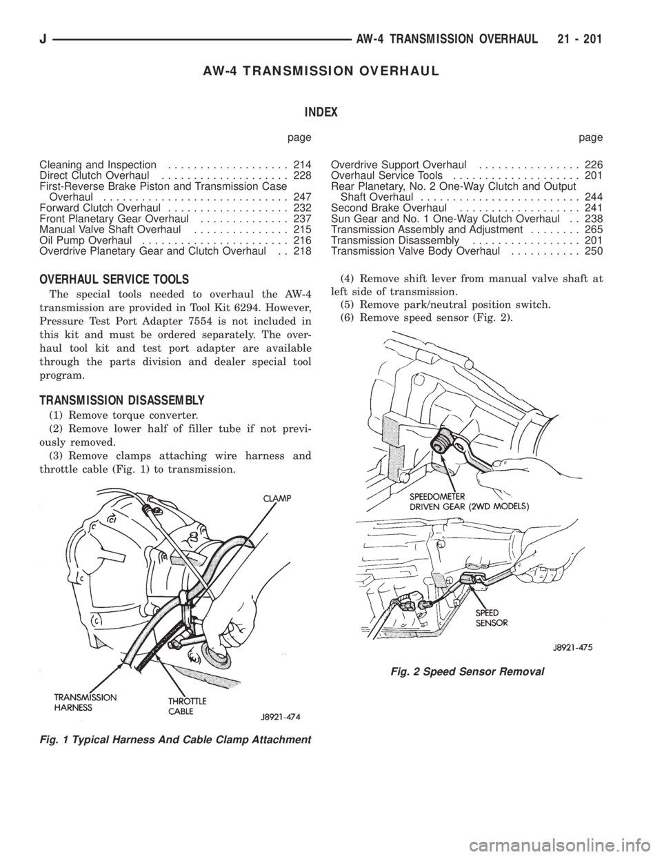
(1) Remove torque converter.
(2) Remove lower half of filler tube if not previ-
ously removed.
(3) Remove clamps attaching wire harness and
throttle cable (Fig. 1) to transmission.(4) Remove shift lever from manual valve shaft at
left side of transmission.
(5) Remove park/neutral position switch.
(6) Remove speed sensor (Fig. 2).
Fig. 1 Typical Harness And Cable Clamp Attachment
Fig. 2 Speed Sensor Removal
JAW-4 TRANSMISSION OVERHAUL 21 - 201
Page 1766 of 2158
(17) Remove valve body from case. Then remove ac-
cumulator springs, spacers and check ball and spring
(Fig. 12).
(18) Remove second brake and clutch accumulator
pistons with compressed air (Fig. 13). Apply air pres-
sure through feed port and ease the pistons out of
the bore.
(19) Remove overdrive brake accumulator piston
with compressed air (Fig. 13).
(20) Remove overdrive clutch accumulator piston
with compressed air (Fig. 13).
(21) Remove throttle cable.
Fig. 12 Removing Accumulator Springs, Spacers
And Check Ball
Fig. 13 Accumulator Piston Removal
21 - 204 AW-4 TRANSMISSION OVERHAULJ
Page 1768 of 2158
(26) Remove thrust bearing, race and overdrive
planetary ring gear (Fig. 18).
(27) Measure stroke length of overdrive brake pis-
ton as follows:
(a) Mount dial indicator on case (Fig. 19).
(b) Mount Gauge Tool 7546 so it contacts piston
(Fig. 19).(c) Apply 57-114 psi air pressure through piston ap-
ply port and note piston stroke on dial indicator. Stroke
length should be: 1.40 - 1.70 mm (0.055 - 0.0699 in.).
(d) If stroke is not within limits, replace piston
and retainer.
(28) Remove overdrive brake snap ring (Fig. 20).
Fig. 18 Removing Bearing, Race And
Planetary Ring Gear
Fig. 19 Measuring Overdrive Brake Piston Stroke
Fig. 20 Removing Overdrive Brake Snap Ring
21 - 206 AW-4 TRANSMISSION OVERHAULJ
Page 1769 of 2158
(29) Remove overdrive brake clutch pack (Fig. 21).
Then measure disc thickness with a micrometer.
Minimum disc thickness is 1.84 mm (0.0724 in.). Re-
place clutch pack if necessary.
(30) Remove overdrive support lower race and up-
per bearing and race assembly (Fig. 22).(31) Remove overdrive support bolts (Fig. 23).
(32) Remove overdrive support snap ring with
Snap Ring Plier Tool 7540 (Fig. 24).
Fig. 21 Removing/Measuring Overdrive Brake Disc
Thickness
Fig. 22 Overdrive Support Bearing/Race Removal
Fig. 23 Overdrive Support Bolt Removal
Fig. 24 Removing/Installing Overdrive Support Snap
Ring
JAW-4 TRANSMISSION OVERHAUL 21 - 207
Page 1770 of 2158
(33) Remove overdrive support (Fig. 25) with
bridge-type Puller 7536.
(34) Remove race from hub of overdrive support
(Fig. 26).(35) Measure stroke length of second coast brake
piston rod as follows:
(a) Make reference mark on piston rod (Fig. 27)
as shown.
(b) Apply 57-114 psi air pressure through piston
feed hole and check stroke length with Gauge Tool
7552 (Fig. 27).
(c) Stroke length should be 1.5 - 3.0 mm (0.059 -
0.118 in.).
(d) If stroke length is incorrect, install new pis-
ton rod and recheck stroke. If stroke is still incor-
rect, replace second coast brake band.
(e) Replacement piston rods are available in two
different lengths which are: 71.4 mm (2.811 in.)
and 72.9 mm (2.870 in.).
Fig. 25 Removing Overdrive Support
Fig. 26 Remove Overdrive Support Race
Fig. 27 Measuring Second Coast Brake Piston Rod
Stroke
21 - 208 AW-4 TRANSMISSION OVERHAULJ