Page 1771 of 2158
(36) Remove second coast brake piston snap ring
with Snap Ring Plier Tool 7540. Then remove piston
cover and piston assembly with compressed air ap-
plied through piston feed hole (Fig. 28).
(37) Disassemble second coast brake piston (Fig.
29).(38) Remove direct and forward clutch assembly
(Fig. 30).
(39) Remove thrust bearing and race from clutch
hub (Fig. 31).
Fig. 28 Removing Second Coast Brake Cover And
Piston
Fig. 29 Second Coast Brake Piston Components
Fig. 30 Removing Direct And Forward Clutch
Assembly
Fig. 31 Bearing And Race Removal From Clutch
Hub
JAW-4 TRANSMISSION OVERHAUL 21 - 209
Page 1772 of 2158
(40) Remove second coast brake band E-ring from
band pin and remove brake band (Fig. 32).
(41) Remove front planetary ring gear front bearing
race and remove front planetary ring gear (Fig. 33).
(42) Remove thrust bearing and rear race from
ring gear (Fig. 34).
Fig. 32 Second Coast Brake Band Removal
Fig. 33 Front Planetary Ring Gear Removal
Fig. 34 Removing Ring Gear Bearing And Rear Race
21 - 210 AW-4 TRANSMISSION OVERHAULJ
Page 1774 of 2158
(47) Measure second brake clutch pack clearance
(Fig. 38). Clearance should be 0.62 - 1.98 mm (0.0244
- 0.0780 in.). Replace discs if clearance is not within
specifications.
(48) Remove second brake clutch pack snap ring
(Fig. 39).
(49) Remove second brake clutch pack (Fig. 40).
Measure disc thickness with micrometer. Minimum
thickness should be 1.84 mm (0.0724 in.). Replace
discs if not within specifications.
(50) Remove bolts attaching park rod bracket to
case. Then disconnect park rod from manual shaft le-
ver and remove rod and bracket (Fig. 41).
Fig. 40 Removing/Measuring Second Brake Clutch
Disc Thickness
Fig. 41 Removing Park Rod And Bracket
Fig. 38 Checking Second Brake Clutch Pack
Clearance
Fig. 39 Removing Second Brake Clutch Pack Snap
Ring
21 - 212 AW-4 TRANSMISSION OVERHAULJ
Page 1775 of 2158
(51) Remove park pawl spring, pin and pawl (Fig.
42).
(52) Measure clearance of first-reverse brake
clutch pack (Fig. 43). Clearance should be: 0.70 - 1.2
mm (0.028 - 0.047 in.). Replace discs if clearance is
not as specified.(53) Remove second brake piston sleeve (Fig. 44).
Cover remover tool with tape to avoid damaging case.
(54) Remove rear planetary gear, second brake
drum and output shaft as an assembly (Fig. 45).
Fig. 42 Removing Park Pawl, Pin And Spring
Fig. 43 Checking First-Reverse Brake Clutch Pack
Clearance
Fig. 44 Removing Second Brake Piston Sleeve
Fig. 45 Removing Rear Planetary, Second Brake
Drum And Output Shaft
JAW-4 TRANSMISSION OVERHAUL 21 - 213
Page 1776 of 2158

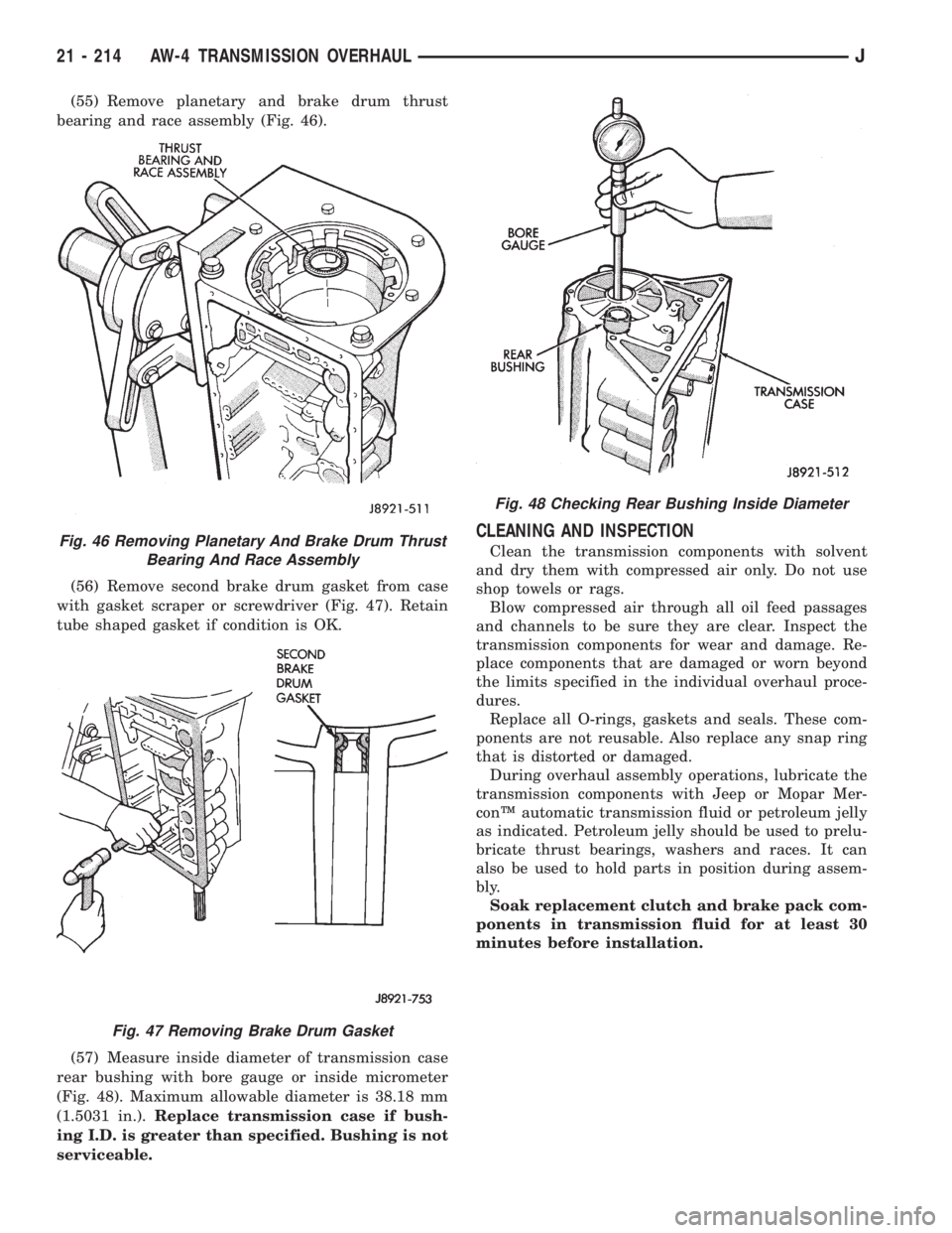
(55) Remove planetary and brake drum thrust
bearing and race assembly (Fig. 46).
(56) Remove second brake drum gasket from case
with gasket scraper or screwdriver (Fig. 47). Retain
tube shaped gasket if condition is OK.
(57) Measure inside diameter of transmission case
rear bushing with bore gauge or inside micrometer
(Fig. 48). Maximum allowable diameter is 38.18 mm
(1.5031 in.).Replace transmission case if bush-
ing I.D. is greater than specified. Bushing is not
serviceable.
CLEANING AND INSPECTION
Clean the transmission components with solvent
and dry them with compressed air only. Do not use
shop towels or rags.
Blow compressed air through all oil feed passages
and channels to be sure they are clear. Inspect the
transmission components for wear and damage. Re-
place components that are damaged or worn beyond
the limits specified in the individual overhaul proce-
dures.
Replace all O-rings, gaskets and seals. These com-
ponents are not reusable. Also replace any snap ring
that is distorted or damaged.
During overhaul assembly operations, lubricate the
transmission components with Jeep or Mopar Mer-
conŸ automatic transmission fluid or petroleum jelly
as indicated. Petroleum jelly should be used to prelu-
bricate thrust bearings, washers and races. It can
also be used to hold parts in position during assem-
bly.
Soak replacement clutch and brake pack com-
ponents in transmission fluid for at least 30
minutes before installation.Fig. 46 Removing Planetary And Brake Drum Thrust
Bearing And Race Assembly
Fig. 47 Removing Brake Drum Gasket
Fig. 48 Checking Rear Bushing Inside Diameter
21 - 214 AW-4 TRANSMISSION OVERHAULJ
Page 1780 of 2158
(13) Install pump in torque converter and check
pump gear rotation. Gears must rotate smoothly
when turned clockwise and counterclockwise.
(14) Lubricate pump O-ring and seal rings with pe-
troleum jelly.
OVERDRIVE PLANETARY GEAR AND CLUTCH
OVERHAUL
GEAR AND CLUTCH DISASSEMBLY
(1) Check operation of one-way clutch in clutch
drum. Hold drum and turn planetary shaft clockwise
and counterclockwise. Shaft should turn clockwise
freely but lock when turned counterclockwise. Re-
place one-way clutch if necessary.(2) Replace overdrive brake clutch pack if discs are
worn below thickness of 1.84 mm (0.0724 in.). This is
clutch pack that fits on clutch drum and in case.
Fig. 1 Overdrive Planetary Gear And Clutch Components
21 - 218 AW-4 TRANSMISSION OVERHAULJ
Page 1788 of 2158

OVERDRIVE SUPPORT OVERHAUL
SUPPORT DISASSEMBLY
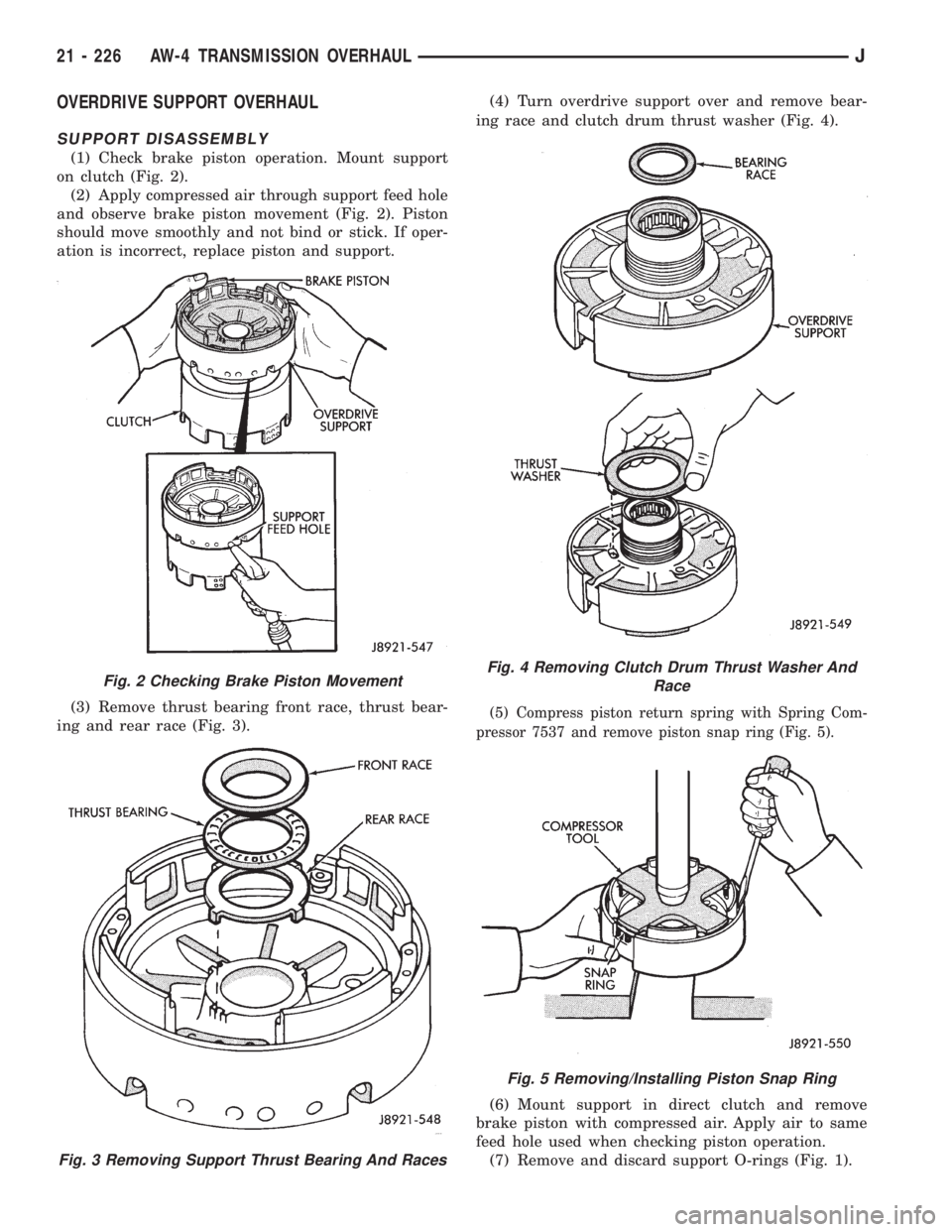
(1) Check brake piston operation. Mount support
on clutch (Fig. 2).
(2) Apply compressed air through support feed hole
and observe brake piston movement (Fig. 2). Piston
should move smoothly and not bind or stick. If oper-
ation is incorrect, replace piston and support.
(3) Remove thrust bearing front race, thrust bear-
ing and rear race (Fig. 3).(4) Turn overdrive support over and remove bear-
ing race and clutch drum thrust washer (Fig. 4).
(5) Compress piston return spring with Spring Com-
pressor 7537 and remove piston snap ring (Fig. 5).
(6) Mount support in direct clutch and remove
brake piston with compressed air. Apply air to same
feed hole used when checking piston operation.
(7) Remove and discard support O-rings (Fig. 1).
Fig. 2 Checking Brake Piston Movement
Fig. 3 Removing Support Thrust Bearing And Races
Fig. 4 Removing Clutch Drum Thrust Washer And
Race
Fig. 5 Removing/Installing Piston Snap Ring
21 - 226 AW-4 TRANSMISSION OVERHAULJ
Page 1789 of 2158

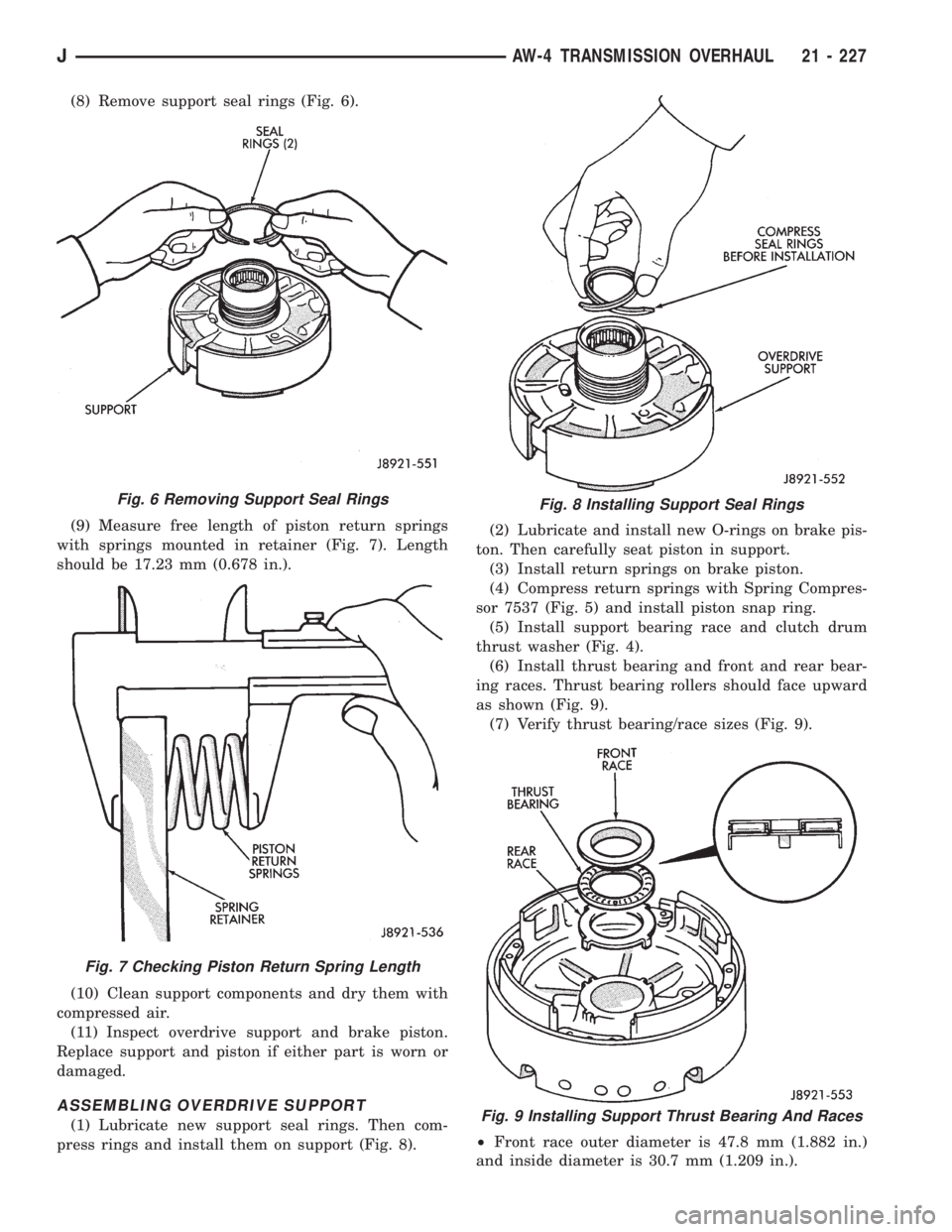
(8) Remove support seal rings (Fig. 6).
(9) Measure free length of piston return springs
with springs mounted in retainer (Fig. 7). Length
should be 17.23 mm (0.678 in.).
(10) Clean support components and dry them with
compressed air.
(11) Inspect overdrive support and brake piston.
Replace support and piston if either part is worn or
damaged.
ASSEMBLING OVERDRIVE SUPPORT
(1) Lubricate new support seal rings. Then com-
press rings and install them on support (Fig. 8).(2) Lubricate and install new O-rings on brake pis-
ton. Then carefully seat piston in support.
(3) Install return springs on brake piston.
(4) Compress return springs with Spring Compres-
sor 7537 (Fig. 5) and install piston snap ring.
(5) Install support bearing race and clutch drum
thrust washer (Fig. 4).
(6) Install thrust bearing and front and rear bear-
ing races. Thrust bearing rollers should face upward
as shown (Fig. 9).
(7) Verify thrust bearing/race sizes (Fig. 9).
²Front race outer diameter is 47.8 mm (1.882 in.)
and inside diameter is 30.7 mm (1.209 in.).
Fig. 6 Removing Support Seal Rings
Fig. 7 Checking Piston Return Spring Length
Fig. 8 Installing Support Seal Rings
Fig. 9 Installing Support Thrust Bearing And Races
JAW-4 TRANSMISSION OVERHAUL 21 - 227