1995 JEEP XJ brake
[x] Cancel search: brakePage 1424 of 2158
energized). This is done to compensate for the re-
duced flow through injector caused by the lowered
voltage.
BRAKE SWITCHÐPCM INPUT
When the brake light switch is activated, the pow-
ertrain control module (PCM) receives an input indi-
cating that the brakes are being applied. After
receiving this input, the PCM maintains idle speed to
a scheduled rpm through control of the idle air con-
trol (IAC) motor. The brake switch input is also used
to operate the speed control system.
CAMSHAFT POSITION SENSORÐPCM INPUT
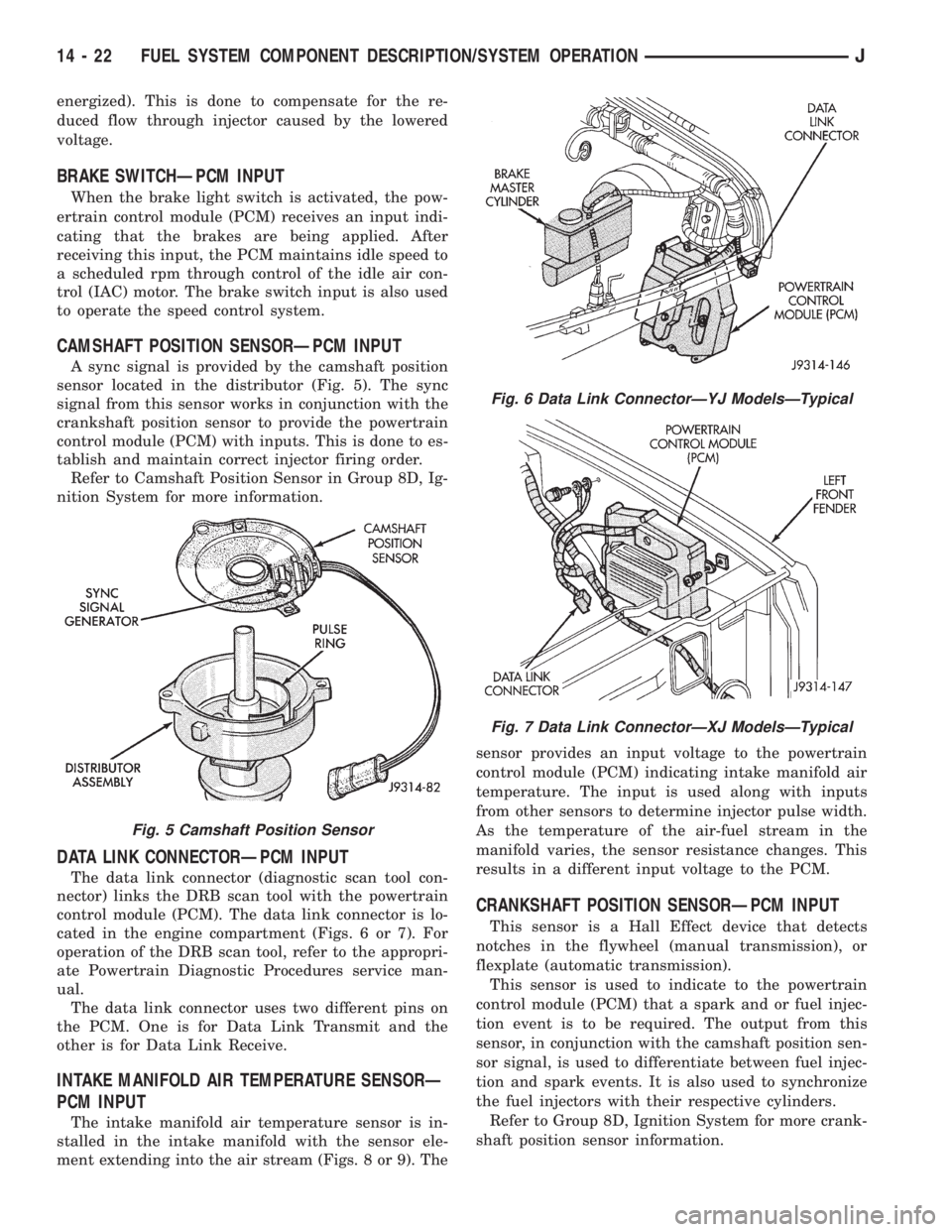
A sync signal is provided by the camshaft position
sensor located in the distributor (Fig. 5). The sync
signal from this sensor works in conjunction with the
crankshaft position sensor to provide the powertrain
control module (PCM) with inputs. This is done to es-
tablish and maintain correct injector firing order.
Refer to Camshaft Position Sensor in Group 8D, Ig-
nition System for more information.
DATA LINK CONNECTORÐPCM INPUT
The data link connector (diagnostic scan tool con-
nector) links the DRB scan tool with the powertrain
control module (PCM). The data link connector is lo-
cated in the engine compartment (Figs. 6 or 7). For
operation of the DRB scan tool, refer to the appropri-
ate Powertrain Diagnostic Procedures service man-
ual.
The data link connector uses two different pins on
the PCM. One is for Data Link Transmit and the
other is for Data Link Receive.
INTAKE MANIFOLD AIR TEMPERATURE SENSORÐ
PCM INPUT
The intake manifold air temperature sensor is in-
stalled in the intake manifold with the sensor ele-
ment extending into the air stream (Figs. 8 or 9). Thesensor provides an input voltage to the powertrain
control module (PCM) indicating intake manifold air
temperature. The input is used along with inputs
from other sensors to determine injector pulse width.
As the temperature of the air-fuel stream in the
manifold varies, the sensor resistance changes. This
results in a different input voltage to the PCM.
CRANKSHAFT POSITION SENSORÐPCM INPUT
This sensor is a Hall Effect device that detects
notches in the flywheel (manual transmission), or
flexplate (automatic transmission).
This sensor is used to indicate to the powertrain
control module (PCM) that a spark and or fuel injec-
tion event is to be required. The output from this
sensor, in conjunction with the camshaft position sen-
sor signal, is used to differentiate between fuel injec-
tion and spark events. It is also used to synchronize
the fuel injectors with their respective cylinders.
Refer to Group 8D, Ignition System for more crank-
shaft position sensor information.
Fig. 5 Camshaft Position Sensor
Fig. 6 Data Link ConnectorÐYJ ModelsÐTypical
Fig. 7 Data Link ConnectorÐXJ ModelsÐTypical
14 - 22 FUEL SYSTEM COMPONENT DESCRIPTION/SYSTEM OPERATIONJ
Page 1427 of 2158
SPEED CONTROLÐPCM INPUT
The speed control system provides three separate
inputs to the powertrain control module (PCM); On/
Off, Set and Resume. The On/Off input informs the
PCM that the speed control system has been acti-
vated. The Set input informs the PCM that a fixed
vehicle speed has been selected. The Resume input
indicates to the PCM that the previous fixed speed is
requested.
The speed control operating range is from 50 km/h
to 142 km/h (35 to 85 mph). Inputs that effect speed
control operation are:
²Brake switch position
²Park/neutral switch
²Vehicle speed sensor
²Throttle position sensor
Refer to Group 8H for further speed control infor-
mation.
SENSOR RETURNÐPCM INPUT
Sensor Return provides a low noise ground refer-
ence for all system sensors.
THROTTLE POSITION SENSOR (TPS)ÐPCM INPUT
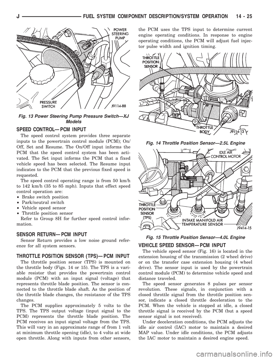
The throttle position sensor (TPS) is mounted on
the throttle body (Figs. 14 or 15). The TPS is a vari-
able resistor that provides the powertrain control
module (PCM) with an input signal (voltage) that
represents throttle blade position. The sensor is con-
nected to the throttle blade shaft. As the position of
the throttle blade changes, the resistance of the TPS
changes.
The PCM supplies approximately 5 volts to the
TPS. The TPS output voltage (input signal to the
PCM) represents the throttle blade position. The
PCM receives an input signal voltage from the TPS.
This will vary in an approximate range of from 1 volt
at minimum throttle opening (idle), to 4 volts at wide
open throttle. Along with inputs from other sensors,the PCM uses the TPS input to determine current
engine operating conditions. In response to engine
operating conditions, the PCM will adjust fuel injec-
tor pulse width and ignition timing.
VEHICLE SPEED SENSORÐPCM INPUT
The vehicle speed sensor (Fig. 16) is located in the
extension housing of the transmission (2 wheel drive)
or on the transfer case extension housing (4 wheel
drive). The sensor input is used by the powertrain
control module (PCM) to determine vehicle speed and
distance traveled.
The speed sensor generates 8 pulses per sensor
revolution. These signals, in conjunction with a
closed throttle signal from the throttle position sen-
sor, indicate a closed throttle deceleration to the
PCM. When the vehicle is stopped at idle, a closed
throttle signal is received by the PCM (but a speed
sensor signal is not received).
Under deceleration conditions, the PCM adjusts the
idle air control (IAC) motor to maintain a desired
MAP value. Under idle conditions, the PCM adjusts
the IAC motor to maintain a desired engine speed.
Fig. 13 Power Steering Pump Pressure SwitchÐXJ
Models
Fig. 14 Throttle Position SensorÐ2.5L Engine
Fig. 15 Throttle Position SensorÐ4.0L Engine
JFUEL SYSTEM COMPONENT DESCRIPTION/SYSTEM OPERATION 14 - 25
Page 1439 of 2158
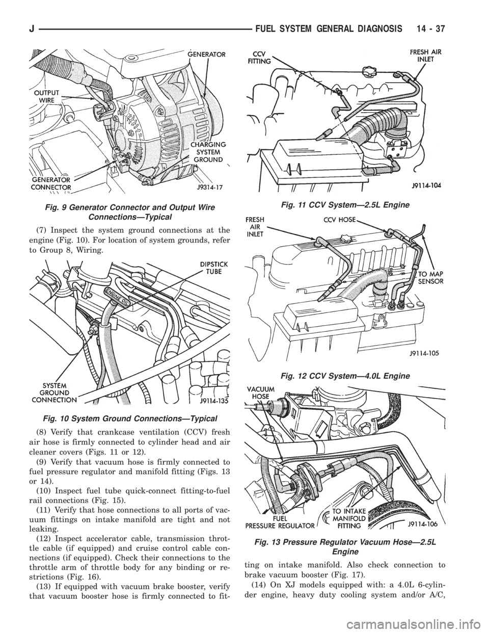
(7) Inspect the system ground connections at the
engine (Fig. 10). For location of system grounds, refer
to Group 8, Wiring.
(8) Verify that crankcase ventilation (CCV) fresh
air hose is firmly connected to cylinder head and air
cleaner covers (Figs. 11 or 12).
(9) Verify that vacuum hose is firmly connected to
fuel pressure regulator and manifold fitting (Figs. 13
or 14).
(10) Inspect fuel tube quick-connect fitting-to-fuel
rail connections (Fig. 15).
(11) Verify that hose connections to all ports of vac-
uum fittings on intake manifold are tight and not
leaking.
(12) Inspect accelerator cable, transmission throt-
tle cable (if equipped) and cruise control cable con-
nections (if equipped). Check their connections to the
throttle arm of throttle body for any binding or re-
strictions (Fig. 16).
(13) If equipped with vacuum brake booster, verify
that vacuum booster hose is firmly connected to fit-ting on intake manifold. Also check connection to
brake vacuum booster (Fig. 17).
(14) On XJ models equipped with: a 4.0L 6-cylin-
der engine, heavy duty cooling system and/or A/C,
Fig. 9 Generator Connector and Output Wire
ConnectionsÐTypical
Fig. 10 System Ground ConnectionsÐTypical
Fig. 11 CCV SystemÐ2.5L Engine
Fig. 12 CCV SystemÐ4.0L Engine
Fig. 13 Pressure Regulator Vacuum HoseÐ2.5L
Engine
JFUEL SYSTEM GENERAL DIAGNOSIS 14 - 37
Page 1440 of 2158
verify that auxiliary radiator cooling fan wire connec-
tor is firmly connected to harness.
(15) Inspect the air cleaner inlet and air cleaner el-
ement for restrictions.(16) Inspect radiator grille area, radiator fins and
air conditioning condenser for restrictions.
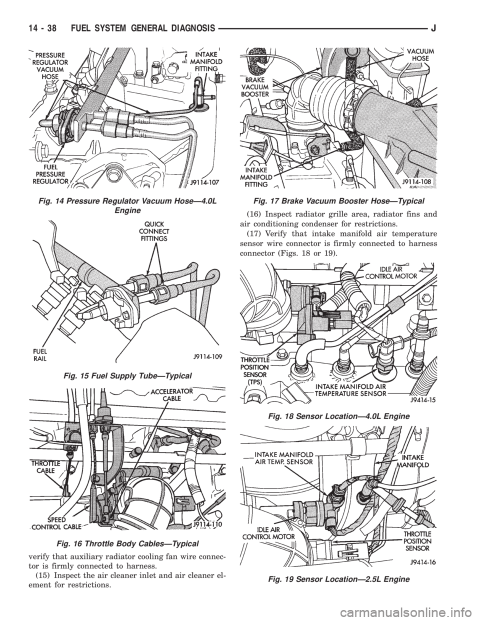
(17) Verify that intake manifold air temperature
sensor wire connector is firmly connected to harness
connector (Figs. 18 or 19).
Fig. 14 Pressure Regulator Vacuum HoseÐ4.0L
Engine
Fig. 15 Fuel Supply TubeÐTypical
Fig. 16 Throttle Body CablesÐTypical
Fig. 17 Brake Vacuum Booster HoseÐTypical
Fig. 18 Sensor LocationÐ4.0L Engine
Fig. 19 Sensor LocationÐ2.5L Engine
14 - 38 FUEL SYSTEM GENERAL DIAGNOSISJ
Page 1451 of 2158
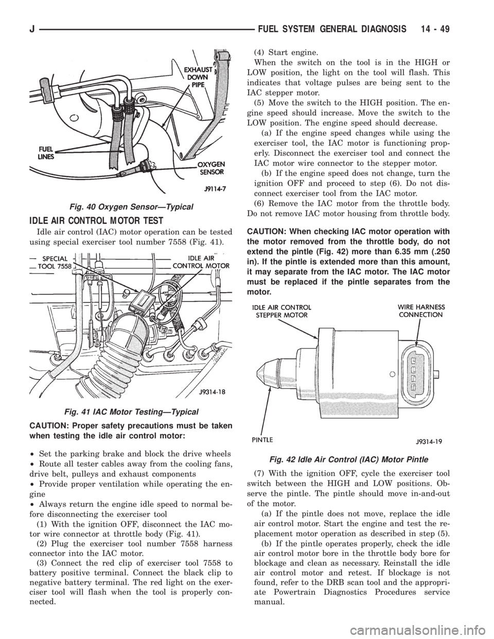
IDLE AIR CONTROL MOTOR TEST
Idle air control (IAC) motor operation can be tested
using special exerciser tool number 7558 (Fig. 41).
CAUTION: Proper safety precautions must be taken
when testing the idle air control motor:
²Set the parking brake and block the drive wheels
²Route all tester cables away from the cooling fans,
drive belt, pulleys and exhaust components
²Provide proper ventilation while operating the en-
gine
²Always return the engine idle speed to normal be-
fore disconnecting the exerciser tool
(1) With the ignition OFF, disconnect the IAC mo-
tor wire connector at throttle body (Fig. 41).
(2) Plug the exerciser tool number 7558 harness
connector into the IAC motor.
(3) Connect the red clip of exerciser tool 7558 to
battery positive terminal. Connect the black clip to
negative battery terminal. The red light on the exer-
ciser tool will flash when the tool is properly con-
nected.(4) Start engine.
When the switch on the tool is in the HIGH or
LOW position, the light on the tool will flash. This
indicates that voltage pulses are being sent to the
IAC stepper motor.
(5) Move the switch to the HIGH position. The en-
gine speed should increase. Move the switch to the
LOW position. The engine speed should decrease.
(a) If the engine speed changes while using the
exerciser tool, the IAC motor is functioning prop-
erly. Disconnect the exerciser tool and connect the
IAC motor wire connector to the stepper motor.
(b) If the engine speed does not change, turn the
ignition OFF and proceed to step (6). Do not dis-
connect exerciser tool from the IAC motor.
(6) Remove the IAC motor from the throttle body.
Do not remove IAC motor housing from throttle body.
CAUTION: When checking IAC motor operation with
the motor removed from the throttle body, do not
extend the pintle (Fig. 42) more than 6.35 mm (.250
in). If the pintle is extended more than this amount,
it may separate from the IAC motor. The IAC motor
must be replaced if the pintle separates from the
motor.
(7) With the ignition OFF, cycle the exerciser tool
switch between the HIGH and LOW positions. Ob-
serve the pintle. The pintle should move in-and-out
of the motor.
(a) If the pintle does not move, replace the idle
air control motor. Start the engine and test the re-
placement motor operation as described in step (5).
(b) If the pintle operates properly, check the idle
air control motor bore in the throttle body bore for
blockage and clean as necessary. Reinstall the idle
air control motor and retest. If blockage is not
found, refer to the DRB scan tool and the appropri-
ate Powertrain Diagnostics Procedures service
manual.
Fig. 40 Oxygen SensorÐTypical
Fig. 41 IAC Motor TestingÐTypical
Fig. 42 Idle Air Control (IAC) Motor Pintle
JFUEL SYSTEM GENERAL DIAGNOSIS 14 - 49
Page 1460 of 2158
MULTI-PORT FUEL INJECTION (MFI)ÐCOMPONENT REMOVAL/INSTALLATION
INDEX
page page
Accelerator Pedal and Throttle Cable........... 58
Air Cleaner Element....................... 59
Air Cleaner Housing....................... 58
Air Conditioning (A/C) Clutch Relay............ 58
Automatic Shutdown (ASD) Relay............. 59
Brake Switch............................ 59
Camshaft Position Sensor................... 60
Crankshaft Position Sensor.................. 60
Engine Coolant Temperature Sensor........... 60
Fuel Filter............................... 60
Fuel Injector............................. 60
Fuel Pressure Regulator.................... 61
Fuel Pump Module........................ 61
Fuel Pump Relay......................... 61
Fuel Rail Assembly........................ 62
Fuel System Pressure Release Procedure....... 62
Fuel Tank Pressure Relief/Rollover Valve........ 62Fuel Tanks.............................. 62
Fuel Tubes/Lines/Hoses and Clamps........... 62
Idle Air Control (IAC) Motor.................. 62
Ignition Coil............................. 62
Intake Manifold........................... 63
Intake Manifold Air Temperature Sensor......... 60
Manifold Absolute Pressure (Map) Sensor....... 63
Oxygen (O2S) Sensor...................... 63
Park Neutral Switch....................... 63
Power Steering Pressure SwitchÐ2.5L
Engine Only............................ 63
Powertrain Control Module (PCM)............. 64
Quick-Connect Fittings..................... 64
Throttle Body............................ 64
Throttle Position Sensor (TPS)............... 65
Torque Converter Clutch Relay............... 65
Vehicle Speed Sensor...................... 66
ACCELERATOR PEDAL AND THROTTLE CABLE
Refer to the Accelerator Pedal and Throttle Cable
section of this group for removal/installation proce-
dures.
AIR CONDITIONING (A/C) CLUTCH RELAY
The A/C clutch relay is located in the power distri-
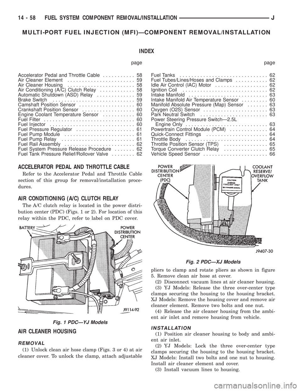
bution center (PDC) (Figs. 1 or 2). For location of this
relay within the PDC, refer to label on PDC cover.
AIR CLEANER HOUSING
REMOVAL
(1) Unlock clean air hose clamp (Figs. 3 or 4) at air
cleaner cover. To unlock the clamp, attach adjustablepliers to clamp and rotate pliers as shown in figure
5. Remove clean air hose at cover.
(2) Disconnect vacuum lines at air cleaner housing.
(3) YJ Models: Release the three over-center type
clamps securing the housing to the housing bracket.
XJ Models: Remove the housing cover and remove air
cleaner element. Remove two bolts and one nut.
(4) Release the air cleaner housing from the ambi-
ent air inlet and remove housing from vehicle.
INSTALLATION
(1) Position air cleaner housing to body and ambi-
ent air inlet.
(2) YJ Models: Lock the three over-center type
clamps securing the housing to the housing bracket.
XJ Models: Install two bolts and one nut to housing.
Install air cleaner element and cover.
(3) Install vacuum lines to housing.
Fig. 1 PDCÐYJ Models
Fig. 2 PDCÐXJ Models
14 - 58 FUEL SYSTEM COMPONENT REMOVAL/INSTALLATIONJ
Page 1461 of 2158
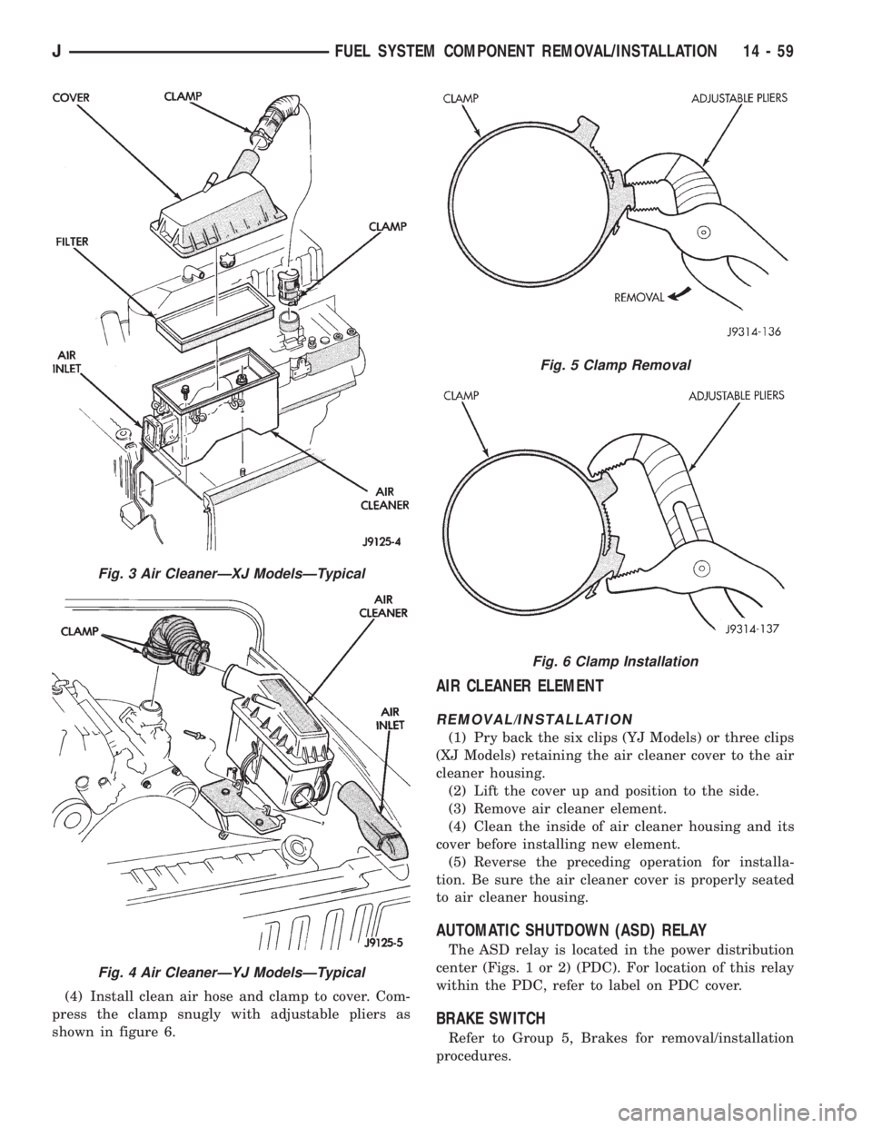
(4) Install clean air hose and clamp to cover. Com-
press the clamp snugly with adjustable pliers as
shown in figure 6.
AIR CLEANER ELEMENT
REMOVAL/INSTALLATION
(1) Pry back the six clips (YJ Models) or three clips
(XJ Models) retaining the air cleaner cover to the air
cleaner housing.
(2) Lift the cover up and position to the side.
(3) Remove air cleaner element.
(4) Clean the inside of air cleaner housing and its
cover before installing new element.
(5) Reverse the preceding operation for installa-
tion. Be sure the air cleaner cover is properly seated
to air cleaner housing.
AUTOMATIC SHUTDOWN (ASD) RELAY
The ASD relay is located in the power distribution
center (Figs. 1 or 2) (PDC). For location of this relay
within the PDC, refer to label on PDC cover.
BRAKE SWITCH
Refer to Group 5, Brakes for removal/installation
procedures.
Fig. 3 Air CleanerÐXJ ModelsÐTypical
Fig. 4 Air CleanerÐYJ ModelsÐTypical
Fig. 5 Clamp Removal
Fig. 6 Clamp Installation
JFUEL SYSTEM COMPONENT REMOVAL/INSTALLATION 14 - 59
Page 1472 of 2158
SERVICE DIAGNOSIS
INDEX
page page
Runout.................................. 4
Unbalance............................... 3Universal Joint Angle Measurement............. 4
Vibration................................. 3
VIBRATION
Tires that are out-of-round or wheels that are un-
balanced will cause a low frequency vibration. Refer
to Group 22, Wheels and Tires for additional infor-
mation.
Brake drums that are unbalanced will cause a
harsh, low frequency vibration. Refer to Group 5,
Brakes for additional information.
Driveline vibration can also result from loose or
damaged engine mounts. Refer to Group 21, Trans-
missions for additional information.
Propeller shaft vibration will increase as the vehi-
cle speed is increased. A vibration that occurs within
a specific speed range is not caused by propeller
shaft unbalance. Defective universal joints or an in-
correct propeller shaft angle are usually the cause.
UNBALANCE
If propeller shaft unbalance is suspected, it can be
verified with the following procedure.
Removing and re-indexing the propeller shaft
180É may eliminate some vibrations.
²Clean all the foreign material from the propeller
shaft and the universal joints.²Inspect the propeller shaft for missing balance
weights, broken welds, and bent areas.If the pro-
peller shaft is bent, it must be replaced.
²Ensure the universal joints are not worn, are prop-
erly installed, and are correctly aligned with the
shaft.
²Check the universal joint clamp screws torque
(1) Raise the vehicle.
(2) Remove the wheel and tires assembly. Install
the wheel lug nuts to retain the brake drums.
(3) Mark and number the shaft six inches from the
yoke end at four positions 90É apart.
(4) Run and accelerate the vehicle until vibration
occurs. Note the intensity and speed the vibration oc-
curred. Stop the engine.
(5) Install a screw clamp at position 1 (Fig. 1).
(6) Start the engine and re-check for vibration. If
there is little or no change in vibration, move the
clamp to one of the other three positions. Repeat the
vibration test.
(7) If there is no difference in vibration at the
other positions, the vibration may not be propshaft
unbalance.
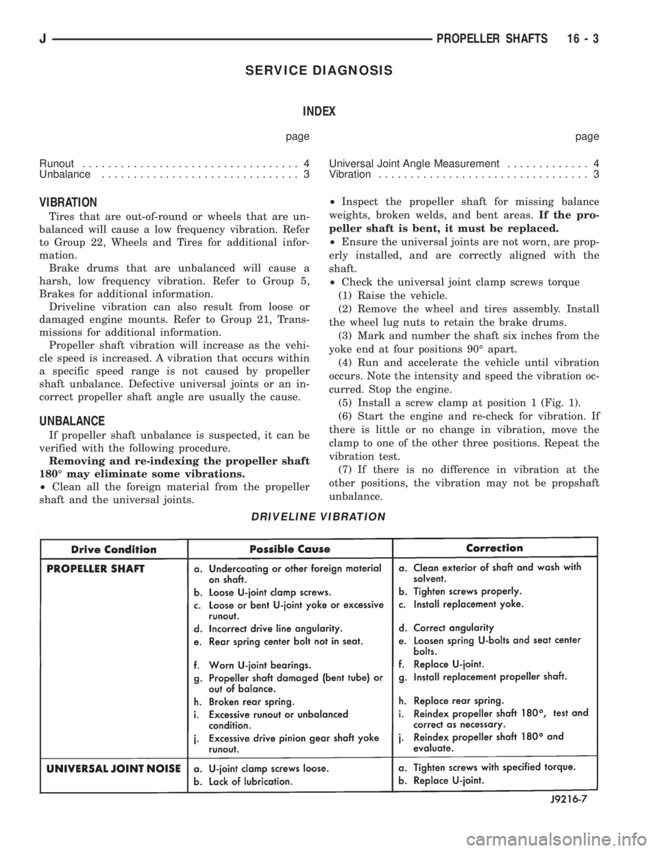
DRIVELINE VIBRATION
JPROPELLER SHAFTS 16 - 3