1995 JEEP XJ ECU
[x] Cancel search: ECUPage 1892 of 2158
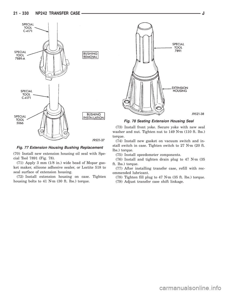
(70) Install new extension housing oil seal with Spe-
cial Tool 7891 (Fig. 78).
(71) Apply 3 mm (1/8 in.) wide bead of Mopar gas-
ket maker, silicone adhesive sealer, or Loctite 518 to
seal surface of extension housing.
(72) Install extension housing on case. Tighten
housing bolts to 41 Nzm (30 ft. lbs.) torque.(73) Install front yoke. Secure yoke with new seal
washer and nut. Tighten nut to 149 Nzm (110 ft. lbs.)
torque.
(74) Install new gasket on vacuum switch and in-
stall switch in case. Tighten switch to 27 Nzm (20 ft.
lbs.) torque.
(75) Install speedometer components.
(76) Install and tighten drain plug to 47 Nzm (35
ft. lbs.) torque.
(77) After installing transfer case, refill with rec-
ommended lubricant.
(78) Tighten fill plug to 47 Nzm (35 ft. lbs.) torque.
(79) Adjust transfer case shift linkage.
Fig. 77 Extension Housing Bushing Replacement
Fig. 78 Seating Extension Housing Seal
21 - 330 NP242 TRANSFER CASEJ
Page 1946 of 2158
(3) For power/manual mirrors, remove the inside
trim cover.
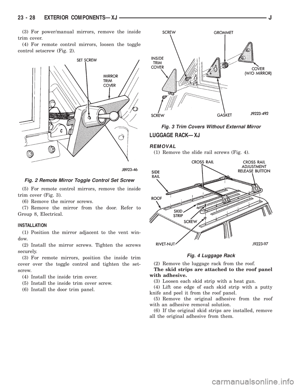
(4) For remote control mirrors, loosen the toggle
control setscrew (Fig. 2).
(5) For remote control mirrors, remove the inside
trim cover (Fig. 3).
(6) Remove the mirror screws.
(7) Remove the mirror from the door. Refer to
Group 8, Electrical.
INSTALLATION
(1) Position the mirror adjacent to the vent win-
dow.
(2) Install the mirror screws. Tighten the screws
securely.
(3) For remote mirrors, position the inside trim
cover over the toggle control and tighten the set-
screw.
(4) Install the inside trim cover.
(5) Install the inside trim cover screw.
(6) Install the door trim panel.
LUGGAGE RACKÐXJ
REMOVAL
(1) Remove the slide rail screws (Fig. 4).
(2) Remove the luggage rack from the roof.
The skid strips are attached to the roof panel
with adhesive.
(3) Loosen each skid strip with a heat gun.
(4) Lift one edge of each skid strip with a putty
knife and peel it from the roof panel.
(5) Remove the original adhesive from the roof
with an adhesive removal solution.
(6) If the original skid strips are installed, remove
all the original adhesive from them.
Fig. 2 Remote Mirror Toggle Control Set Screw
Fig. 3 Trim Covers Without External Mirror
Fig. 4 Luggage Rack
23 - 28 EXTERIOR COMPONENTSÐXJJ
Page 1953 of 2158
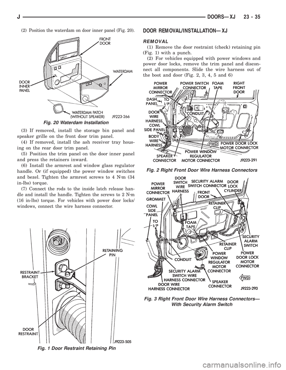
(2) Position the waterdam on door inner panel (Fig. 20).
(3) If removed, install the storage bin panel and
speaker grille on the front door trim panel.
(4) If removed, install the ash receiver tray hous-
ing on the rear door trim panel.
(5) Position the trim panel on the door inner panel
and press the retainers inward.
(6) Install the armrest and window glass regulator
handle. Or (if equipped) the power window switches
and bezel. Tighten the armrest screws to 4 Nzm (34
in-lbs) torque.
(7) Connect the rods to the inside latch release han-
dle and install the handle. Tighten the screws to 2 Nzm
(16 in-lbs) torque. For vehicles with power door locks/
windows, connect the wire harness connector.
DOOR REMOVAL/INSTALLATIONÐXJ
REMOVAL
(1) Remove the door restraint (check) retaining pin
(Fig. 1) with a punch.
(2) For vehicles equipped with power windows and
power door locks, remove the trim panel and discon-
nect all components. Slide the wire harness out of
the boot and door (Fig. 2, 3, 4, 5 and 6)
Fig. 1 Door Restraint Retaining Pin
Fig. 20 Waterdam Installation
Fig. 2 Right Front Door Wire Harness Connectors
Fig. 3 Right Front Door Wire Harness ConnectorsÐ
With Security Alarm Switch
JDOORSÐXJ 23 - 35
Page 1965 of 2158
(3) Remove the window weatherstrip seals from
the door.
(4) Remove the trim panel and waterdam from
door inner panel.
(5) Remove the channel/division bar screws. Drill
out the rivet head to remove it from the inner panel.
(6) Tilt the channel/division bar forward and re-
move it from the door.
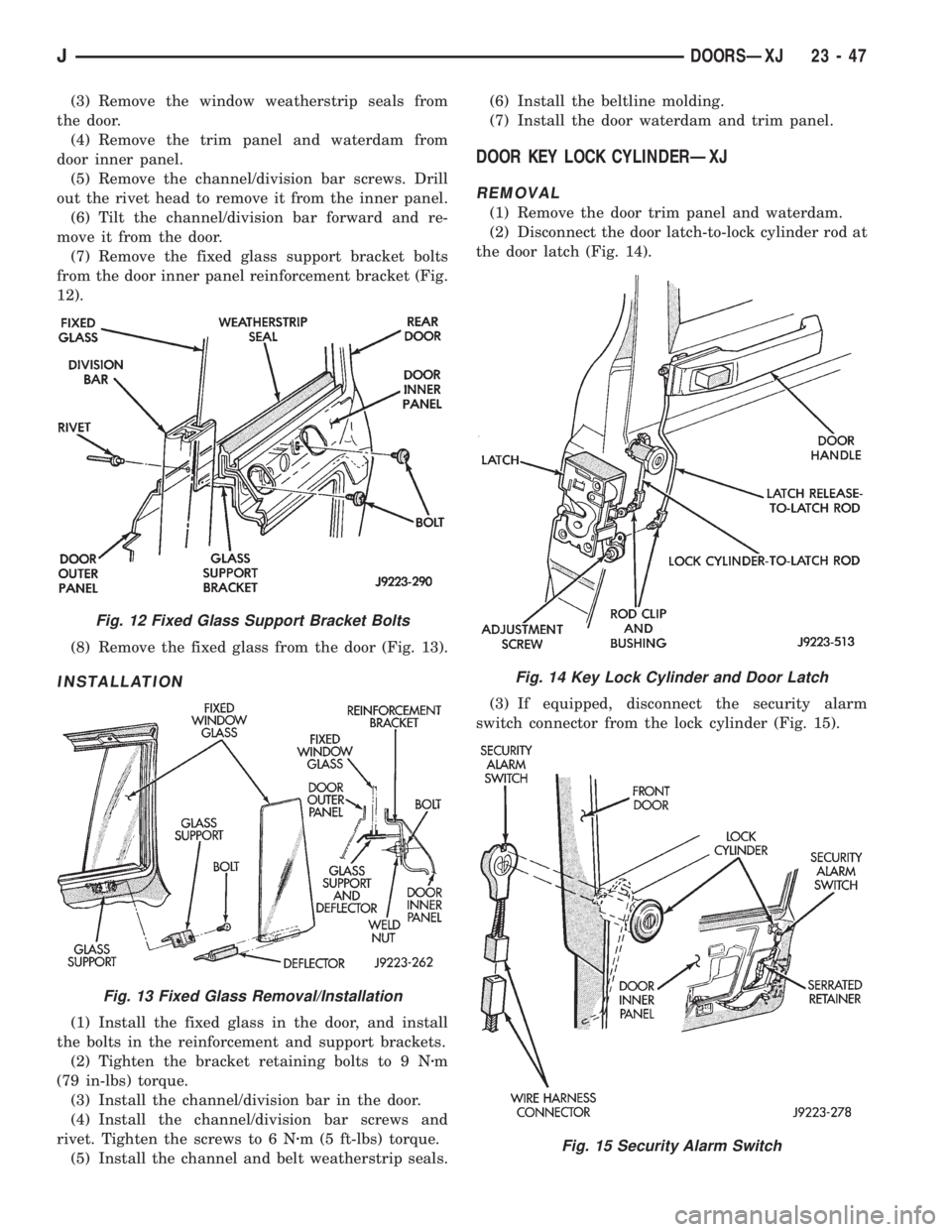
(7) Remove the fixed glass support bracket bolts
from the door inner panel reinforcement bracket (Fig.
12).
(8) Remove the fixed glass from the door (Fig. 13).
INSTALLATION
(1) Install the fixed glass in the door, and install
the bolts in the reinforcement and support brackets.
(2) Tighten the bracket retaining bolts to 9 Nzm
(79 in-lbs) torque.
(3) Install the channel/division bar in the door.
(4) Install the channel/division bar screws and
rivet. Tighten the screws to 6 Nzm (5 ft-lbs) torque.
(5) Install the channel and belt weatherstrip seals.(6) Install the beltline molding.
(7) Install the door waterdam and trim panel.
DOOR KEY LOCK CYLINDERÐXJ
REMOVAL
(1) Remove the door trim panel and waterdam.
(2) Disconnect the door latch-to-lock cylinder rod at
the door latch (Fig. 14).
(3) If equipped, disconnect the security alarm
switch connector from the lock cylinder (Fig. 15).
Fig. 12 Fixed Glass Support Bracket Bolts
Fig. 13 Fixed Glass Removal/Installation
Fig. 14 Key Lock Cylinder and Door Latch
Fig. 15 Security Alarm Switch
JDOORSÐXJ 23 - 47
Page 1966 of 2158
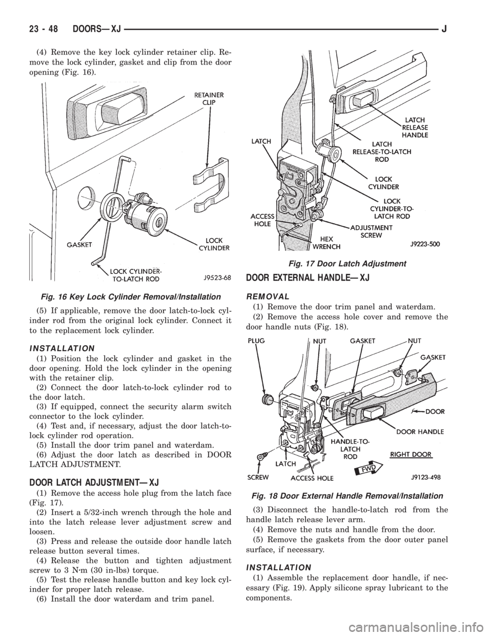
(4) Remove the key lock cylinder retainer clip. Re-
move the lock cylinder, gasket and clip from the door
opening (Fig. 16).
(5) If applicable, remove the door latch-to-lock cyl-
inder rod from the original lock cylinder. Connect it
to the replacement lock cylinder.
INSTALLATION
(1) Position the lock cylinder and gasket in the
door opening. Hold the lock cylinder in the opening
with the retainer clip.
(2) Connect the door latch-to-lock cylinder rod to
the door latch.
(3) If equipped, connect the security alarm switch
connector to the lock cylinder.
(4) Test and, if necessary, adjust the door latch-to-
lock cylinder rod operation.
(5) Install the door trim panel and waterdam.
(6) Adjust the door latch as described in DOOR
LATCH ADJUSTMENT.
DOOR LATCH ADJUSTMENTÐXJ
(1) Remove the access hole plug from the latch face
(Fig. 17).
(2) Insert a 5/32-inch wrench through the hole and
into the latch release lever adjustment screw and
loosen.
(3) Press and release the outside door handle latch
release button several times.
(4) Release the button and tighten adjustment
screw to 3 Nzm (30 in-lbs) torque.
(5) Test the release handle button and key lock cyl-
inder for proper latch release.
(6) Install the door waterdam and trim panel.
DOOR EXTERNAL HANDLEÐXJ
REMOVAL
(1) Remove the door trim panel and waterdam.
(2) Remove the access hole cover and remove the
door handle nuts (Fig. 18).
(3) Disconnect the handle-to-latch rod from the
handle latch release lever arm.
(4) Remove the nuts and handle from the door.
(5) Remove the gaskets from the door outer panel
surface, if necessary.
INSTALLATION
(1) Assemble the replacement door handle, if nec-
essary (Fig. 19). Apply silicone spray lubricant to the
components.
Fig. 16 Key Lock Cylinder Removal/Installation
Fig. 17 Door Latch Adjustment
Fig. 18 Door External Handle Removal/Installation
23 - 48 DOORSÐXJJ
Page 1976 of 2158
LIFTGATEÐXJ
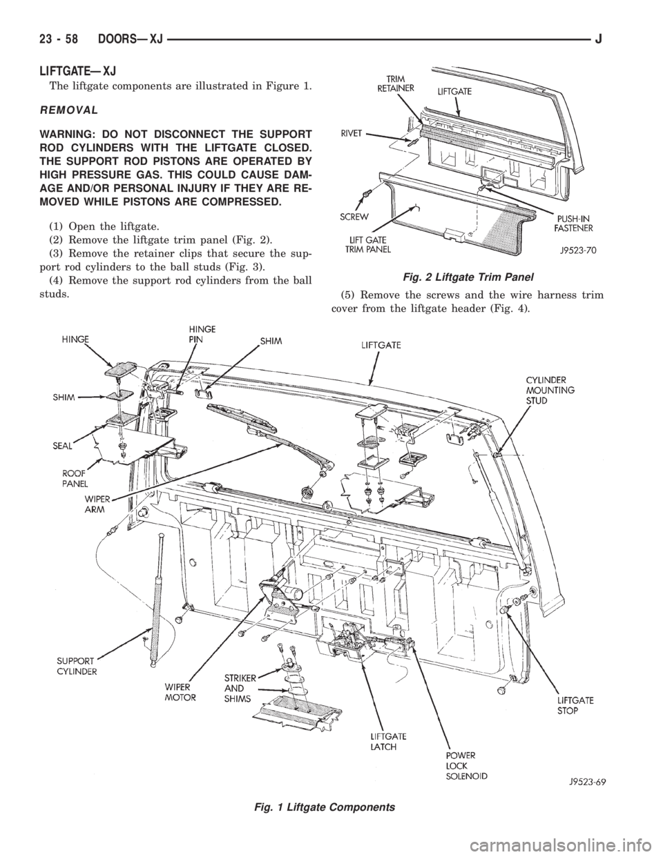
The liftgate components are illustrated in Figure 1.
REMOVAL
WARNING: DO NOT DISCONNECT THE SUPPORT
ROD CYLINDERS WITH THE LIFTGATE CLOSED.
THE SUPPORT ROD PISTONS ARE OPERATED BY
HIGH PRESSURE GAS. THIS COULD CAUSE DAM-
AGE AND/OR PERSONAL INJURY IF THEY ARE RE-
MOVED WHILE PISTONS ARE COMPRESSED.
(1) Open the liftgate.
(2) Remove the liftgate trim panel (Fig. 2).
(3) Remove the retainer clips that secure the sup-
port rod cylinders to the ball studs (Fig. 3).
(4) Remove the support rod cylinders from the ball
studs.
(5) Remove the screws and the wire harness trim
cover from the liftgate header (Fig. 4).
Fig. 1 Liftgate Components
Fig. 2 Liftgate Trim Panel
23 - 58 DOORSÐXJJ
Page 1980 of 2158

(7) Remove the latch striker screws from the scuff
plate and cross sill (Fig. 16)
(8) Remove the striker and shim from the retainer.
INSTALLATION
(1) Install the key lock cylinder. Secure the lock
cylinder with the retainer clip (Fig. 17).
(2) Position the latch in the liftgate.
(3) Connect the latch rod.
(4) Install and tighten the latch screws to 12 Nzm
(110 in-lbs) torque.
(5) Install the striker retainer, shim, striker and
screws in the scuff plate cross sill.
LIFTGATE SUPPORT ROD CYLINDERÐXJ
REMOVAL
WARNING: DO NOT REMOVE A SUPPORT ROD
CYLINDER WITH THE LIFTGATE CLOSED. EACH
SUPPORT ROD PISTON IS OPERATED BY HIGH
PRESSURE GAS. IT CAN CAUSE DAMAGE AND/OR
PERSONAL INJURY IF IT IS REMOVED WITH THE
PISTON COMPRESSED. DO NOT ATTEMPT TO DIS-
ASSEMBLE OR REPAIR A SUPPORT ROD CYLIN-
DER.
(1) Open the liftgate.
(2) Support the liftgate in the open position.
(3) Remove the clips that attach the support rod
and cylinder to the ball studs (Fig. 1).
(4) Disconnect the support rod and cylinder from
the ball studs and remove the cylinder from vehicle
(Fig. 2).
(5) De-pressurize the original rod cylinder before
disposal. Refer to the procedure below.
INSTALLATION
(1) Connect the replacement support rod and cylin-
der to the ball studs.
(2) Secure the support rod and cylinder to the ball
studs with the retainer clips.
(3) Remove the support from the liftgate and test
the operation of the support rod.
Fig. 16 Liftgate Latch Striker
Fig. 17 Liftgate Key Lock Cylinder and Latch
Fig. 1 Support Rod Retainer Clip
23 - 62 DOORSÐXJJ
Page 1981 of 2158
LIFTGATE SUPPORT ROD CYLINDER DISPOSALÐ
XJ
WARNING: SAFETY GOGGLES MUST BE WORN
DURING THE DISPOSAL PROCEDURE. THE HIGH
PRESSURE GAS CHARGE IN THE SUPPORT ROD
CYLINDERS WILL BE RELEASED DURING THE
PROCEDURE.
(1) Remove the support rod cylinder(s) from the
liftgate.
(2) Position the support rod cylinder horizontally
in a vise and clamp the cylinder securely.
(3) Wrap the cylinder with 4-5 layers of shop tow-
els.
(4) Measure 1 and 1/2 inches inward from the end
of the cylinder. Mark this location on the towels with
chalk. The cylinder will be punctured at this location
to release the gas charge.
(5) Use a punch and hammer to puncture cylinder.
Force the punch through towels and into the cylinder
with a hammer. Continue striking the punch until
the gas begins to escapebut do not remove the
punch.
(6) Hold the towels and punch in position until all
the gas has escaped. Complete de-pressurization will
require about 4 to 10 seconds. After all the gas has
escaped, slowly remove the punch.
(7) Hold a towel over the hole in cylinder and press
the support rod piston all the way into the cylinder
to purge remaining oil.
(8) Remove the support rod cylinder from the vise
and discard it.
(9) If both support rod cylinders are being re-
placed, repeat this procedure for the remaining cylin-
der.
LIFTGATE SUPPORT ROD BALL STUD
REPLACEMENTÐXJ
REMOVAL
(1) Open the liftgate.
(2) Support the liftgate in the open position.
(3) Remove the retainer clip that attaches the sup-
port rod and cylinder to the ball stud.
(4) Disconnect the support rod from the ball stud.
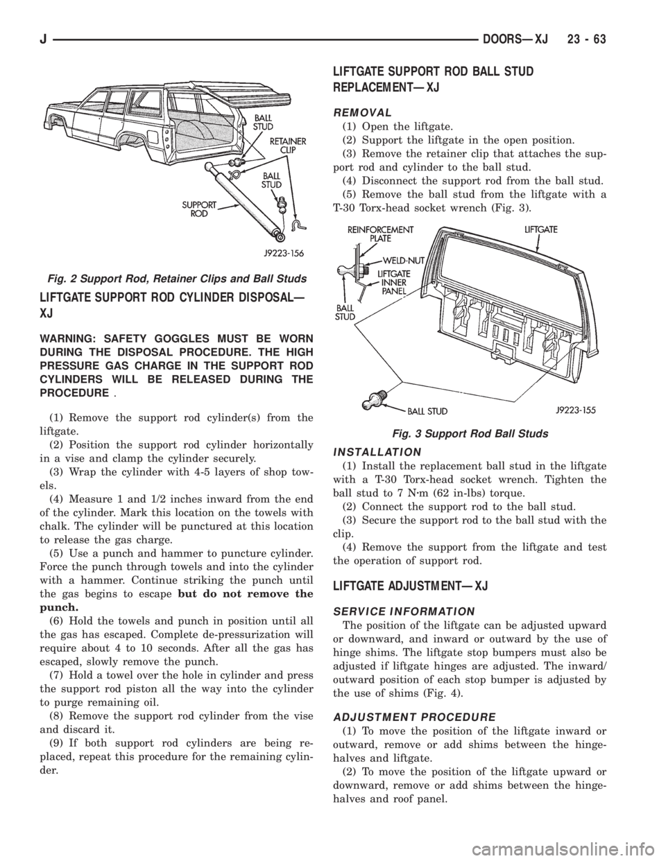
(5) Remove the ball stud from the liftgate with a
T-30 Torx-head socket wrench (Fig. 3).
INSTALLATION
(1) Install the replacement ball stud in the liftgate
with a T-30 Torx-head socket wrench. Tighten the
ball stud to 7 Nzm (62 in-lbs) torque.
(2) Connect the support rod to the ball stud.
(3) Secure the support rod to the ball stud with the
clip.
(4) Remove the support from the liftgate and test
the operation of support rod.
LIFTGATE ADJUSTMENTÐXJ
SERVICE INFORMATION
The position of the liftgate can be adjusted upward
or downward, and inward or outward by the use of
hinge shims. The liftgate stop bumpers must also be
adjusted if liftgate hinges are adjusted. The inward/
outward position of each stop bumper is adjusted by
the use of shims (Fig. 4).
ADJUSTMENT PROCEDURE
(1) To move the position of the liftgate inward or
outward, remove or add shims between the hinge-
halves and liftgate.
(2) To move the position of the liftgate upward or
downward, remove or add shims between the hinge-
halves and roof panel.
Fig. 2 Support Rod, Retainer Clips and Ball Studs
Fig. 3 Support Rod Ball Studs
JDOORSÐXJ 23 - 63