1995 JEEP XJ ECU
[x] Cancel search: ECUPage 1624 of 2158
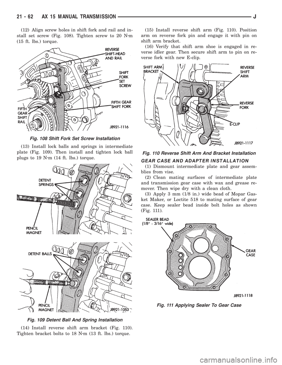
(12) Align screw holes in shift fork and rail and in-
stall set screw (Fig. 108). Tighten screw to 20 Nzm
(15 ft. lbs.) torque.
(13) Install lock balls and springs in intermediate
plate (Fig. 109). Then install and tighten lock ball
plugs to 19 Nzm (14 ft. lbs.) torque.
(14) Install reverse shift arm bracket (Fig. 110).
Tighten bracket bolts to 18 Nzm (13 ft. lbs.) torque.(15) Install reverse shift arm (Fig. 110). Position
arm on reverse fork pin and engage it with pin on
shift arm bracket.
(16) Verify that shift arm shoe is engaged in re-
verse idler gear. Then secure shift arm to pin on re-
verse fork with new E-clip.
GEAR CASE AND ADAPTER INSTALLATION
(1) Dismount intermediate plate and gear assem-
blies from vise.
(2) Clean mating surfaces of intermediate plate
and transmission gear case with wax and grease re-
mover. Then wipe dry with a clean cloth.
(3) Apply 3 mm (1/8 in.) wide bead of Mopar Gas-
ket Maker, or Loctite 518 to mating surface of gear
case. Keep sealer bead inside bolt holes as shown
(Fig. 111).
Fig. 108 Shift Fork Set Screw Installation
Fig. 109 Detent Ball And Spring Installation
Fig. 110 Reverse Shift Arm And Bracket Installation
Fig. 111 Applying Sealer To Gear Case
21 - 62 AX 15 MANUAL TRANSMISSIONJ
Page 1625 of 2158
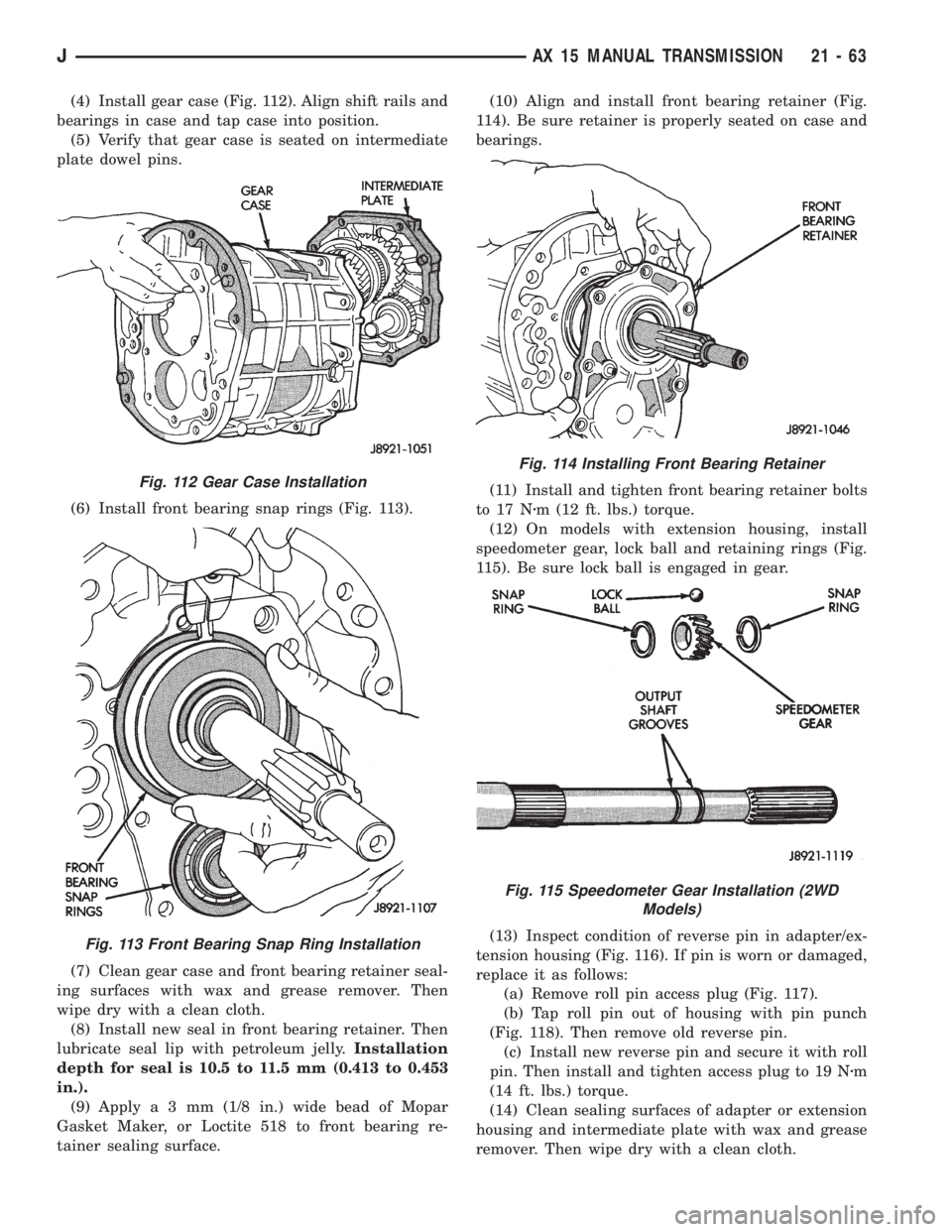
(4) Install gear case (Fig. 112). Align shift rails and
bearings in case and tap case into position.
(5) Verify that gear case is seated on intermediate
plate dowel pins.
(6) Install front bearing snap rings (Fig. 113).
(7) Clean gear case and front bearing retainer seal-
ing surfaces with wax and grease remover. Then
wipe dry with a clean cloth.
(8) Install new seal in front bearing retainer. Then
lubricate seal lip with petroleum jelly.Installation
depth for seal is 10.5 to 11.5 mm (0.413 to 0.453
in.).
(9) Applya3mm(1/8 in.) wide bead of Mopar
Gasket Maker, or Loctite 518 to front bearing re-
tainer sealing surface.(10) Align and install front bearing retainer (Fig.
114). Be sure retainer is properly seated on case and
bearings.
(11) Install and tighten front bearing retainer bolts
to 17 Nzm (12 ft. lbs.) torque.
(12) On models with extension housing, install
speedometer gear, lock ball and retaining rings (Fig.
115). Be sure lock ball is engaged in gear.
(13) Inspect condition of reverse pin in adapter/ex-
tension housing (Fig. 116). If pin is worn or damaged,
replace it as follows:
(a) Remove roll pin access plug (Fig. 117).
(b) Tap roll pin out of housing with pin punch
(Fig. 118). Then remove old reverse pin.
(c) Install new reverse pin and secure it with roll
pin. Then install and tighten access plug to 19 Nzm
(14 ft. lbs.) torque.
(14) Clean sealing surfaces of adapter or extension
housing and intermediate plate with wax and grease
remover. Then wipe dry with a clean cloth.
Fig. 112 Gear Case Installation
Fig. 113 Front Bearing Snap Ring Installation
Fig. 114 Installing Front Bearing Retainer
Fig. 115 Speedometer Gear Installation (2WD
Models)
JAX 15 MANUAL TRANSMISSION 21 - 63
Page 1638 of 2158
LEAK TESTING WITH AIR PRESSURE
This test involves closing off the transmission open-
ings and pressurizing the transmission to 8 psi with
Air Pump Tool 7700.
A soapy water solution is applied to suspected leak
points before and during the pressure test. Leaks will
be indicated by the presence of air bubbles coming
through the solution.
Some transmission openings such as the fill tube
and front cooler line fitting can be closed off with a
rubber plug or similar device. Plugs can secured with
wire or duct tape.
The transmission rear output shaft opening is
closed off simply by leaving the transfer case bolted
in place. However, if the transfer case has been re-
moved, a shipping plug can used to close off this
opening.
The torque converter hub opening in the pump and
the pump vent require special tools to close them off.
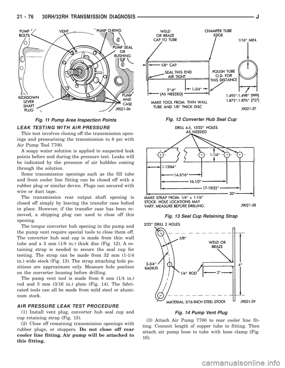
The converter hub seal cap is made from thin wall
tube anda3mm(1/8 in.) thick disc (Fig. 12). A re-
taining strap is needed to secure the seal cup for
testing. The strap can be made from 32 mm (1-1/4
in.) wide stock (Fig. 13). The strap attaching hole po-
sitions are approximate only. Measure hole position
on the converter housing before drilling.
The pump vent tool is made from 6 mm (1/4 in.)
rod and 5 mm (3/16 in.) plate (Fig. 14). The fabri-
cated tools can all be made from mild steel or alumi-
num stock.
AIR PRESSURE LEAK TEST PROCEDURE
(1) Install vent plug, converter hub seal cup and
cup retaining strap (Fig. 15).
(2) Close off remaining transmission openings with
rubber plugs, or stoppers.Do not close off rear
cooler line fitting. Air pump will be attached to
this fitting.(3) Attach Air Pump 7700 to rear cooler line fit-
ting. Connect length of copper tube to fitting. Then
attach air pump hose to tube with hose clamp (Fig.
16).
Fig. 11 Pump Area Inspection PointsFig. 12 Converter Hub Seal Cup
Fig. 13 Seal Cup Retaining Strap
Fig. 14 Pump Vent Plug
21 - 76 30RH/32RH TRANSMISSION DIAGNOSISJ
Page 1669 of 2158
Governor/Park Gear Cleaning and Inspection
Thoroughly clean all the governor parts in a suit-
able cleaning solution but do not use any type of
caustic cleaning agents.
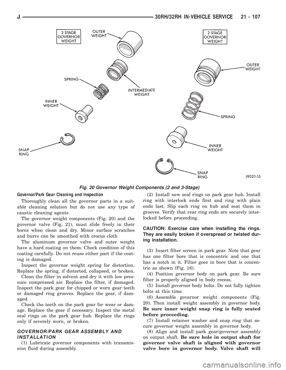
The governor weight components (Fig. 20) and the
governor valve (Fig. 21), must slide freely in their
bores when clean and dry. Minor surface scratches
and burrs can be smoothed with crocus cloth
The aluminum governor valve and outer weight
have a hard coating on them. Check condition of this
coating carefully. Do not reuse either part if the coat-
ing is damaged.
Inspect the governor weight spring for distortion.
Replace the spring, if distorted, collapsed, or broken.
Clean the filter in solvent and dry it with low pres-
sure compressed air. Replace the filter, if damaged.
Inspect the park gear for chipped or worn gear teeth
or damaged ring grooves. Replace the gear, if dam-
aged.
Check the teeth on the park gear for wear or dam-
age. Replace the gear if necessary. Inspect the metal
seal rings on the park gear hub. Replace the rings
only if severely worn, or broken.
GOVERNOR/PARK GEAR ASSEMBLY AND
INSTALLATION
(1) Lubricate governor components with transmis-
sion fluid during assembly.(2) Install new seal rings on park gear hub. Install
ring with interlock ends first and ring with plain
ends last. Slip each ring on hub and seat them in
grooves. Verify that rear ring ends are securely inter-
locked before proceeding.
CAUTION: Exercise care when installing the rings.
They are easily broken if overspread or twisted dur-
ing installation.
(3) Insert filter screen in park gear. Note that gear
has one filter bore that is concentric and one that
has a notch in it. Filter goes in bore that is concen-
tric as shown (Fig. 16).
(4) Position governor body on park gear. Be sure
filter is properly aligned in body recess.
(5) Install governor body bolts. Do not fully tighten
bolts at this time.
(6) Assemble governor weight components (Fig.
20). Then install weight assembly in governor body.
Be sure inner weight snap ring is fully seated
before proceeding.
(7) Install retainer washer and snap ring that se-
cure governor weight assembly in governor body.
(8) Align and install park gear/governor assembly
on output shaft.Be sure hole in output shaft for
governor valve shaft is aligned with governor
valve bore in governor body. Valve shaft will
Fig. 20 Governor Weight Components (2 and 3-Stage)
J30RH/32RH IN-VEHICLE SERVICE 21 - 107
Page 1675 of 2158
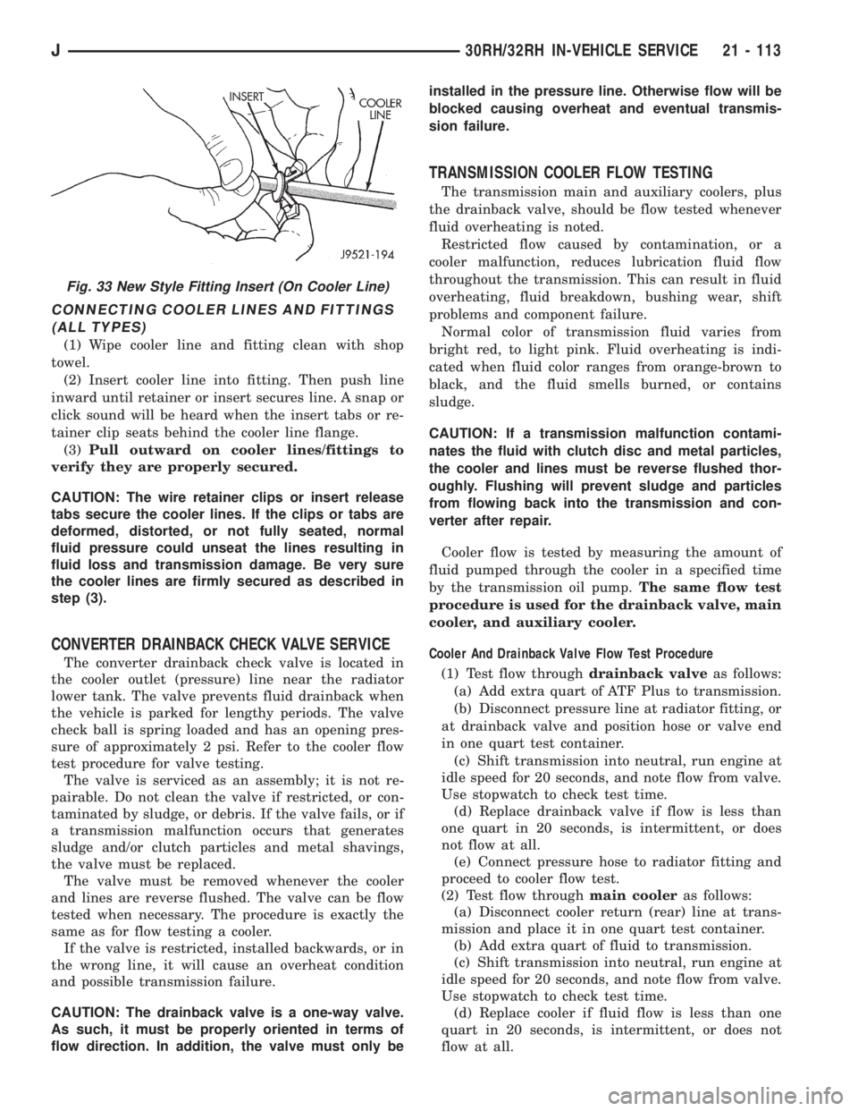
CONNECTING COOLER LINES AND FITTINGS
(ALL TYPES)
(1) Wipe cooler line and fitting clean with shop
towel.
(2) Insert cooler line into fitting. Then push line
inward until retainer or insert secures line. A snap or
click sound will be heard when the insert tabs or re-
tainer clip seats behind the cooler line flange.
(3)Pull outward on cooler lines/fittings to
verify they are properly secured.
CAUTION: The wire retainer clips or insert release
tabs secure the cooler lines. If the clips or tabs are
deformed, distorted, or not fully seated, normal
fluid pressure could unseat the lines resulting in
fluid loss and transmission damage. Be very sure
the cooler lines are firmly secured as described in
step (3).
CONVERTER DRAINBACK CHECK VALVE SERVICE
The converter drainback check valve is located in
the cooler outlet (pressure) line near the radiator
lower tank. The valve prevents fluid drainback when
the vehicle is parked for lengthy periods. The valve
check ball is spring loaded and has an opening pres-
sure of approximately 2 psi. Refer to the cooler flow
test procedure for valve testing.
The valve is serviced as an assembly; it is not re-
pairable. Do not clean the valve if restricted, or con-
taminated by sludge, or debris. If the valve fails, or if
a transmission malfunction occurs that generates
sludge and/or clutch particles and metal shavings,
the valve must be replaced.
The valve must be removed whenever the cooler
and lines are reverse flushed. The valve can be flow
tested when necessary. The procedure is exactly the
same as for flow testing a cooler.
If the valve is restricted, installed backwards, or in
the wrong line, it will cause an overheat condition
and possible transmission failure.
CAUTION: The drainback valve is a one-way valve.
As such, it must be properly oriented in terms of
flow direction. In addition, the valve must only beinstalled in the pressure line. Otherwise flow will be
blocked causing overheat and eventual transmis-
sion failure.
TRANSMISSION COOLER FLOW TESTING
The transmission main and auxiliary coolers, plus
the drainback valve, should be flow tested whenever
fluid overheating is noted.
Restricted flow caused by contamination, or a
cooler malfunction, reduces lubrication fluid flow
throughout the transmission. This can result in fluid
overheating, fluid breakdown, bushing wear, shift
problems and component failure.
Normal color of transmission fluid varies from
bright red, to light pink. Fluid overheating is indi-
cated when fluid color ranges from orange-brown to
black, and the fluid smells burned, or contains
sludge.
CAUTION: If a transmission malfunction contami-
nates the fluid with clutch disc and metal particles,
the cooler and lines must be reverse flushed thor-
oughly. Flushing will prevent sludge and particles
from flowing back into the transmission and con-
verter after repair.
Cooler flow is tested by measuring the amount of
fluid pumped through the cooler in a specified time
by the transmission oil pump.The same flow test
procedure is used for the drainback valve, main
cooler, and auxiliary cooler.
Cooler And Drainback Valve Flow Test Procedure
(1) Test flow throughdrainback valveas follows:
(a) Add extra quart of ATF Plus to transmission.
(b) Disconnect pressure line at radiator fitting, or
at drainback valve and position hose or valve end
in one quart test container.
(c) Shift transmission into neutral, run engine at
idle speed for 20 seconds, and note flow from valve.
Use stopwatch to check test time.
(d) Replace drainback valve if flow is less than
one quart in 20 seconds, is intermittent, or does
not flow at all.
(e) Connect pressure hose to radiator fitting and
proceed to cooler flow test.
(2) Test flow throughmain cooleras follows:
(a) Disconnect cooler return (rear) line at trans-
mission and place it in one quart test container.
(b) Add extra quart of fluid to transmission.
(c) Shift transmission into neutral, run engine at
idle speed for 20 seconds, and note flow from valve.
Use stopwatch to check test time.
(d) Replace cooler if fluid flow is less than one
quart in 20 seconds, is intermittent, or does not
flow at all.
Fig. 33 New Style Fitting Insert (On Cooler Line)
J30RH/32RH IN-VEHICLE SERVICE 21 - 113
Page 1677 of 2158
30RH/32RH TRANSMISSION REMOVAL AND INSTALLATION
INDEX
page page
ConverterÐPump SealÐDrive Plate Service.... 116
Transmission and Converter Installation........ 117Transmission and Converter Removal......... 115
TRANSMISSION AND CONVERTER REMOVAL
(1) Remove fan shroud attaching bolts.
(2) Disconnect transmission fill tube at upper
bracket.
(3) Raise vehicle.
(4) Remove inspection cover from converter hous-
ing and remove skid plate for access, if necessary.
(5) Remove transmission fill tube and fill tube O-
ring.
(6) Remove starter motor.
(7) Mark propeller shafts and axle yokes for align-
ment reference.
(8) Disconnect propeller shafts at yokes. Secure
shafts to frame rails with wire.
(9) Disconnect exhaust pipes at exhaust manifolds,
if necessary.
(10) Drain transfer case lubricant, if transfer case
will also be serviced.
(11) Disconnect vehicle speed sensor wires.
(12) Disconnect transfer case shift linkage.
(13) Disconnect gearshift cable/linkage and throttle
valve cable at transmission levers.
(14) Disconnect transfer case vent hose. Then dis-
connect indicator switch wires on XJ, or vacuum
switch harness on YJ.
(15) Remove wire harness from clips on transfer
case.
(16) Remove transfer case attaching nuts and re-
move transfer case. Use transmission jack or helper
to support and remove transfer case.
(17) Disconnect park/neutral position switch wires.
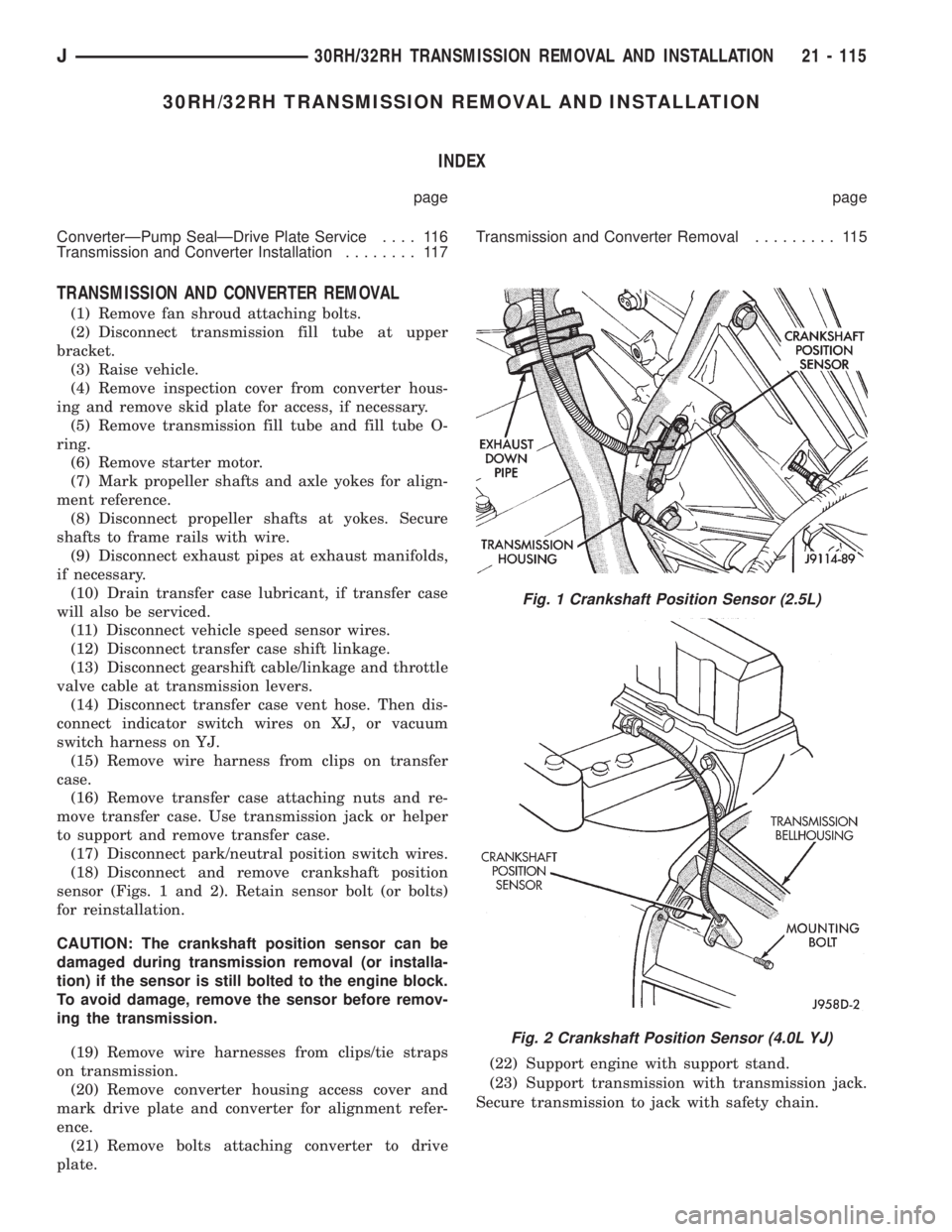
(18) Disconnect and remove crankshaft position
sensor (Figs. 1 and 2). Retain sensor bolt (or bolts)
for reinstallation.
CAUTION: The crankshaft position sensor can be
damaged during transmission removal (or installa-
tion) if the sensor is still bolted to the engine block.
To avoid damage, remove the sensor before remov-
ing the transmission.
(19) Remove wire harnesses from clips/tie straps
on transmission.
(20) Remove converter housing access cover and
mark drive plate and converter for alignment refer-
ence.
(21) Remove bolts attaching converter to drive
plate.(22) Support engine with support stand.
(23) Support transmission with transmission jack.
Secure transmission to jack with safety chain.
Fig. 1 Crankshaft Position Sensor (2.5L)
Fig. 2 Crankshaft Position Sensor (4.0L YJ)
J30RH/32RH TRANSMISSION REMOVAL AND INSTALLATION 21 - 115
Page 1679 of 2158
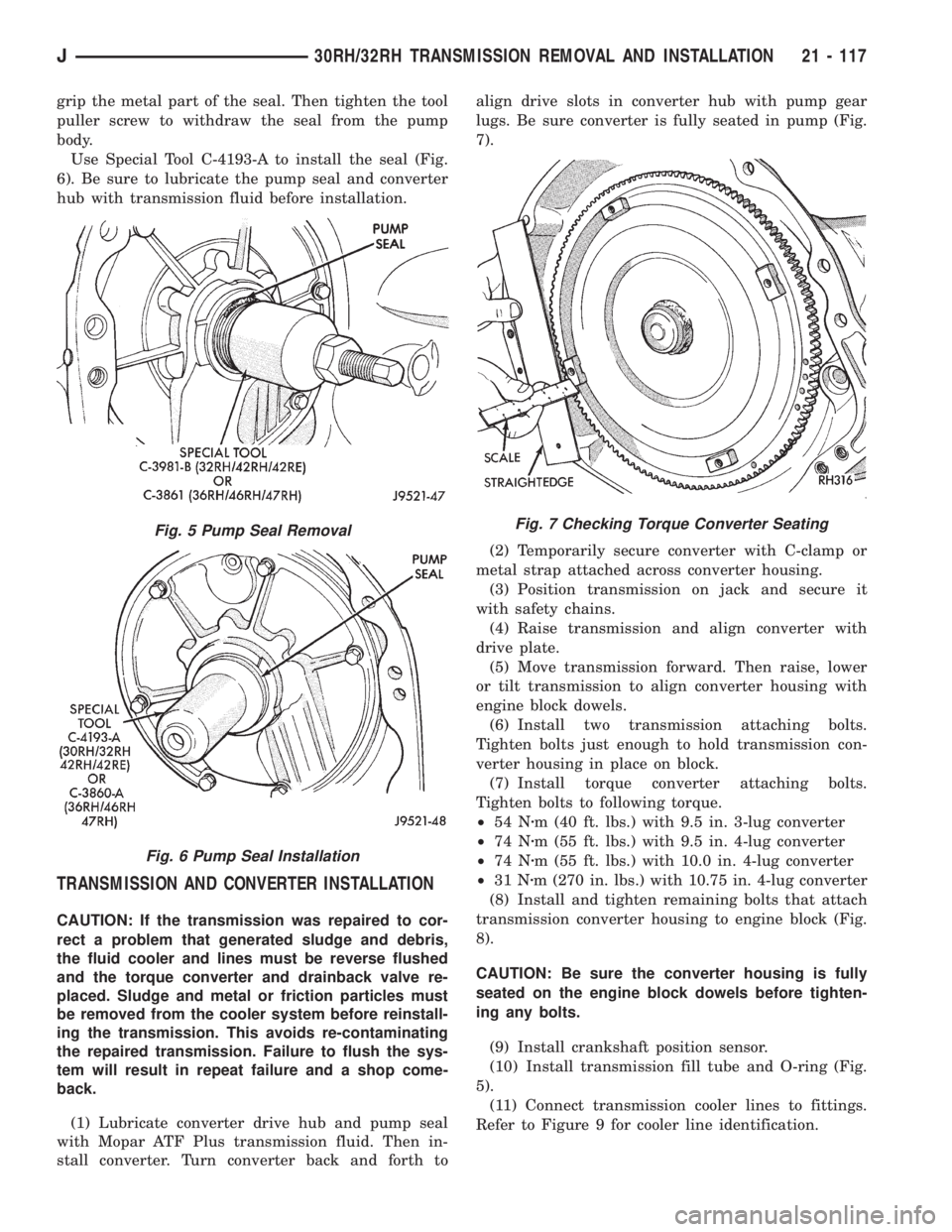
grip the metal part of the seal. Then tighten the tool
puller screw to withdraw the seal from the pump
body.
Use Special Tool C-4193-A to install the seal (Fig.
6). Be sure to lubricate the pump seal and converter
hub with transmission fluid before installation.
TRANSMISSION AND CONVERTER INSTALLATION
CAUTION: If the transmission was repaired to cor-
rect a problem that generated sludge and debris,
the fluid cooler and lines must be reverse flushed
and the torque converter and drainback valve re-
placed. Sludge and metal or friction particles must
be removed from the cooler system before reinstall-
ing the transmission. This avoids re-contaminating
the repaired transmission. Failure to flush the sys-
tem will result in repeat failure and a shop come-
back.
(1) Lubricate converter drive hub and pump seal
with Mopar ATF Plus transmission fluid. Then in-
stall converter. Turn converter back and forth toalign drive slots in converter hub with pump gear
lugs. Be sure converter is fully seated in pump (Fig.
7).
(2) Temporarily secure converter with C-clamp or
metal strap attached across converter housing.
(3) Position transmission on jack and secure it
with safety chains.
(4) Raise transmission and align converter with
drive plate.
(5) Move transmission forward. Then raise, lower
or tilt transmission to align converter housing with
engine block dowels.
(6) Install two transmission attaching bolts.
Tighten bolts just enough to hold transmission con-
verter housing in place on block.
(7) Install torque converter attaching bolts.
Tighten bolts to following torque.
²54 Nzm (40 ft. lbs.) with 9.5 in. 3-lug converter
²74 Nzm (55 ft. lbs.) with 9.5 in. 4-lug converter
²74 Nzm (55 ft. lbs.) with 10.0 in. 4-lug converter
²31 Nzm (270 in. lbs.) with 10.75 in. 4-lug converter
(8) Install and tighten remaining bolts that attach
transmission converter housing to engine block (Fig.
8).
CAUTION: Be sure the converter housing is fully
seated on the engine block dowels before tighten-
ing any bolts.
(9) Install crankshaft position sensor.
(10) Install transmission fill tube and O-ring (Fig.
5).
(11) Connect transmission cooler lines to fittings.
Refer to Figure 9 for cooler line identification.
Fig. 5 Pump Seal Removal
Fig. 6 Pump Seal Installation
Fig. 7 Checking Torque Converter Seating
J30RH/32RH TRANSMISSION REMOVAL AND INSTALLATION 21 - 117
Page 1685 of 2158
(31) Mark position of governor body on park gear
with center punch or scriber.
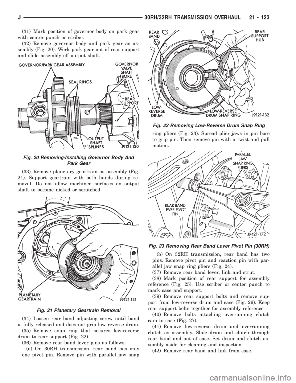
(32) Remove governor body and park gear as as-
sembly (Fig. 20). Work park gear out of rear support
and slide assembly off output shaft.
(33) Remove planetary geartrain as assembly (Fig.
21). Support geartrain with both hands during re-
moval. Do not allow machined surfaces on output
shaft to become nicked or scratched.
(34) Loosen rear band adjusting screw until band
is fully released and does not grip low reverse drum.
(35) Remove snap ring that secures low-reverse
drum to rear support (Fig. 22).
(36) Remove rear band lever pins as follows:
(a) On 30RH transmission, rear band has only
one pivot pin. Remove pin with parallel jaw snapring pliers (Fig. 23). Spread plier jaws in pin bore
to grip pin. Then remove pin with a twist and pull
motion.
(b) On 32RH transmission, rear band has two
pins. Remove pivot pin and reaction pin with par-
allel jaw snap ring pliers (Fig. 24).
(37) Remove rear band lever, link and strut.
(38) Mark position of rear support for assembly
reference (Fig. 25). Use scriber or center punch to
mark case and support.
(39) Remove rear support bolts and remove sup-
port from low-reverse drum and case (Fig. 26). Keep
rear support bolts together for assembly reference.
(40) Remove bolts attaching overrunning clutch
cam to case (Fig. 27).
(41) Remove low-reverse drum and overrunning
clutch as assembly. Slide drum and clutch through
rear band and out of case. Set drum and clutch as-
sembly aside for cleaning and inspection.
(42) Remove rear band and link from case.
Fig. 20 Removing/Installing Governor Body And
Park Gear
Fig. 21 Planetary Geartrain Removal
Fig. 22 Removing Low-Reverse Drum Snap Ring
Fig. 23 Removing Rear Band Lever Pivot Pin (30RH)
J30RH/32RH TRANSMISSION OVERHAUL 21 - 123