1995 JEEP XJ ECU
[x] Cancel search: ECUPage 1567 of 2158
(21) Remove clutch release bearing, release fork
and retainer clip.
(22) Remove clutch housing from transmission.
TRANSMISSION INSTALLATION
(1) Install clutch housing on transmission. Tighten
housing bolts to 37 Nzm (27 ft. lbs.) torque.
(2) Lubricate contact surfaces of release fork pivot
ball stud and release fork with high temp grease.
Then install release bearing, fork and retainer clip.
(3) Mount transmission on transmission jack.
(4) Lightly lubricate pilot bearing and transmis-
sion input shaft splines with Mopar high temp
grease.
(5) Align transmission input shaft, release bearing,
and clutch disc splines. Then slide transmission into
place.
(6) Install and tighten clutch housing-to-engine
bolts to 38 Nzm (28 ft. lbs.) torque.Be sure the
housing is properly seated on engine block be-
fore tightening bolts.
(7) Lower transmission approximately 7-8 cm (3
in.) for access to shift tower. Be sure transmission is
in first or third gear.
(8) Reach up and around transmission and insert
shift lever in shift tower. Press lever retainer down-
ward and turn it clockwise to lock it in place. Then
install lever dust boot on shift tower.
(9) Install slave cylinder in clutch housing.
(10) Align and install transfer case on and trans-
mission. Tighten transfer case-to-transmission nuts
to 35 Nzm (26 ft. lbs.) torque.
(11) Connect transfer case vent hose and shift link-
age. Check and adjust linkage if necessary.
(12) Connect transfer case vent hose.
(13) Secure wire harnesses in clips/tie straps on
transmission and transfer case.
(14) Connect backup light switch wires.
(15) Connect vehicle speed sensor wires.
(16) Install and connect crankshaft position sensor.
(17) Install rear crossmember (Fig. 5). On XJ,
tighten crossmember-to-frame bolts to 41 Nzm (31 ft.
lbs.) torque. Then tighten transmission-to-rear sup-
port bolts/nuts to 45 Nzm (33 ft. lbs.) torque. On YJ,
tighten bolts/nuts to indicated torque (Fig. 5).
(18) Remove jack stand.
(19) Align and install front/rear propeller shafts.
Tighten shaft U-joint clamp bolts to 19 Nzm (170 in.
lbs.) torque.
(20) Install skid plate, if equipped. Tighten bolts to
42 Nzm (31 ft. lbs.) torque. Tighten stud nuts to 17
Nzm (150 in. lbs.) torque.
(21) Top off transmission and transfer case lubri-
cant levels.
(22) Lower vehicle.
TRANSMISSION DISASSEMBLY AND OVERHAUL
ADAPTER HOUSING AND FRONT BEARING
RETAINER REMOVAL
(1) Drain transmission lubricant.
(2) Remove release bearing and lever.
(3) Remove clutch housing bolts and remove hous-
ing.
(4) On 2-wheel drive models, remove vehicle speed
sensor, speedometer adapter and speedometer driven
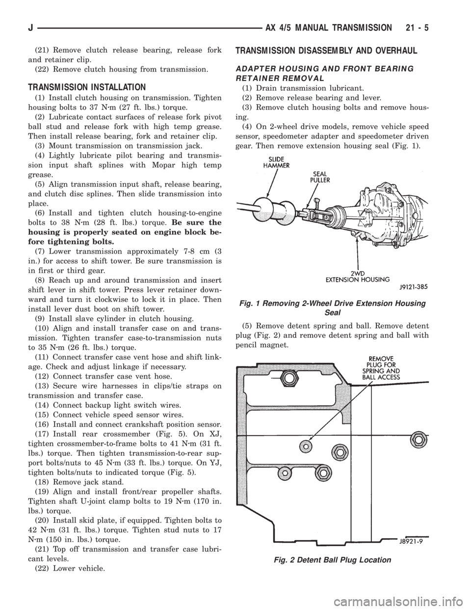
gear. Then remove extension housing seal (Fig. 1).
(5) Remove detent spring and ball. Remove detent
plug (Fig. 2) and remove detent spring and ball with
pencil magnet.
Fig. 1 Removing 2-Wheel Drive Extension Housing
Seal
Fig. 2 Detent Ball Plug Location
JAX 4/5 MANUAL TRANSMISSION 21 - 5
Page 1579 of 2158
ASSEMBLING OUTPUT SHAFT, INPUT SHAFT
AND COUNTER GEAR
(1) If front bearing was removed from input shaft,
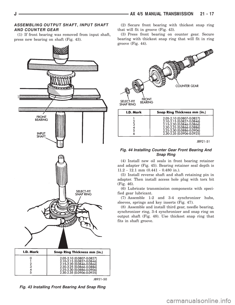
press new bearing on shaft (Fig. 43).(2) Secure front bearing with thickest snap ring
that will fit in groove (Fig. 43).
(3) Press front bearing on counter gear. Secure
bearing with thickest snap ring that will fit in ring
groove (Fig. 44).
(4) Install new oil seals in front bearing retainer
and adapter (Fig. 45). Bearing retainer seal depth is
11.2 - 12.1 mm (0.441 - 0.480 in.).
(5) Install reverse shaft and shaft retaining pin in
adapter. Then install access hole plug with torx bit
(Fig. 46).
(6) Lubricate transmission components with speci-
fied gear lubricant.
(7) Assemble 1-2 and 3-4 synchronizer hubs,
sleeves, springs and key inserts (Fig. 47).
(8) Assemble and install third gear, needle bearing,
synchronizer ring, 3-4 synchronizer and snap ring on
output shaft (Fig. 48). Use thickest snap ring that
fits in shaft groove.
Fig. 43 Installing Front Bearing And Snap Ring
Fig. 44 Installing Counter Gear Front Bearing And
Snap Ring
JAX 4/5 MANUAL TRANSMISSION 21 - 17
Page 1598 of 2158
(6) On XJ, remove rear crossmember. On YJ, re-
move skid plate (Fig. 1).
(7) Disconnect transmission shift linkage, speed-
ometer cable, transfer case vacuum lines and clutch
hydraulic lines.
(8) Lower transmission-transfer case assembly no
more than 7.6 cm (3 in.) for access to shift lever.
(9) Reach up and around transmission case and
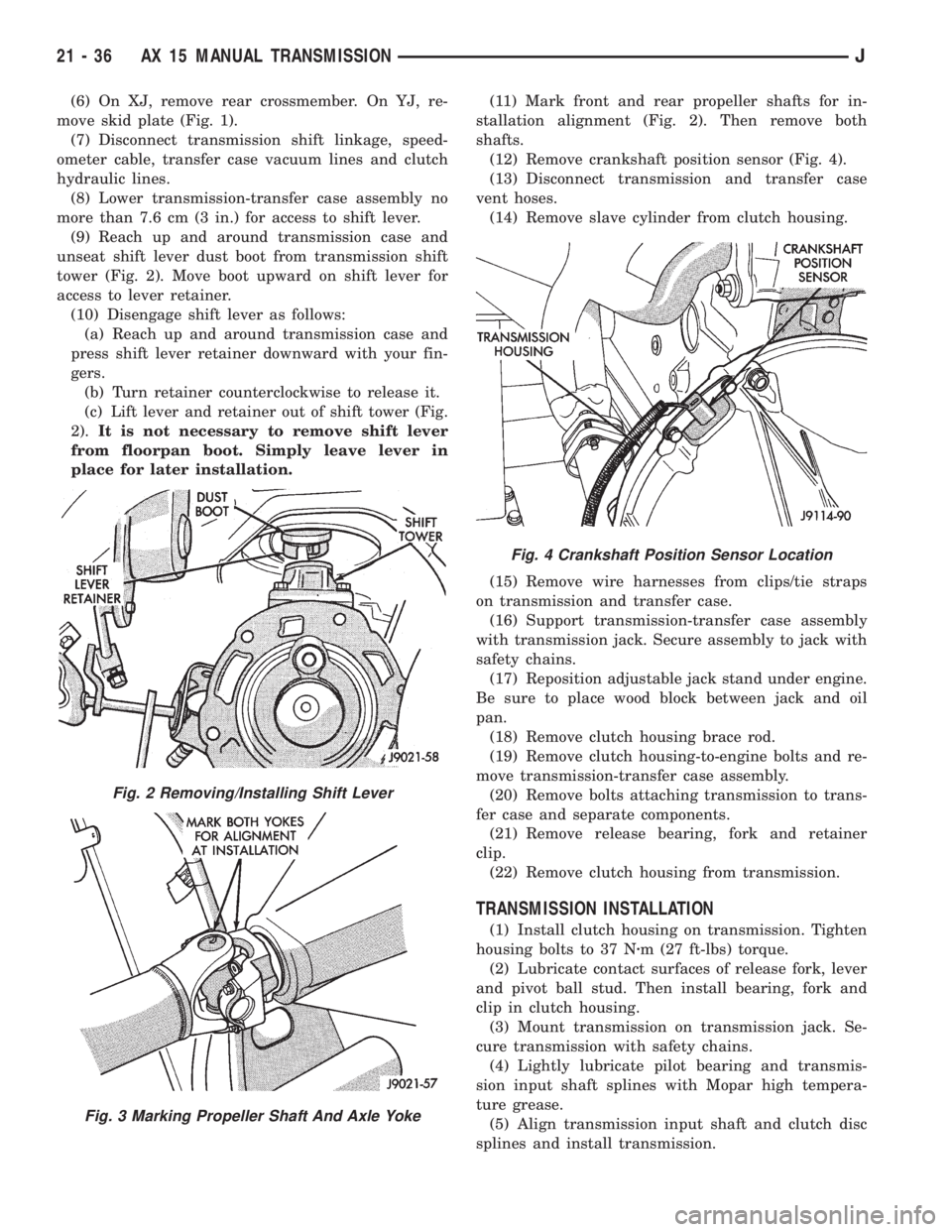
unseat shift lever dust boot from transmission shift
tower (Fig. 2). Move boot upward on shift lever for
access to lever retainer.
(10) Disengage shift lever as follows:
(a) Reach up and around transmission case and
press shift lever retainer downward with your fin-
gers.
(b) Turn retainer counterclockwise to release it.
(c) Lift lever and retainer out of shift tower (Fig.
2).It is not necessary to remove shift lever
from floorpan boot. Simply leave lever in
place for later installation.(11) Mark front and rear propeller shafts for in-
stallation alignment (Fig. 2). Then remove both
shafts.
(12) Remove crankshaft position sensor (Fig. 4).
(13) Disconnect transmission and transfer case
vent hoses.
(14) Remove slave cylinder from clutch housing.
(15) Remove wire harnesses from clips/tie straps
on transmission and transfer case.
(16) Support transmission-transfer case assembly
with transmission jack. Secure assembly to jack with
safety chains.
(17) Reposition adjustable jack stand under engine.
Be sure to place wood block between jack and oil
pan.
(18) Remove clutch housing brace rod.
(19) Remove clutch housing-to-engine bolts and re-
move transmission-transfer case assembly.
(20) Remove bolts attaching transmission to trans-
fer case and separate components.
(21) Remove release bearing, fork and retainer
clip.
(22) Remove clutch housing from transmission.
TRANSMISSION INSTALLATION
(1) Install clutch housing on transmission. Tighten
housing bolts to 37 Nzm (27 ft-lbs) torque.
(2) Lubricate contact surfaces of release fork, lever
and pivot ball stud. Then install bearing, fork and
clip in clutch housing.
(3) Mount transmission on transmission jack. Se-
cure transmission with safety chains.
(4) Lightly lubricate pilot bearing and transmis-
sion input shaft splines with Mopar high tempera-
ture grease.
(5) Align transmission input shaft and clutch disc
splines and install transmission.
Fig. 2 Removing/Installing Shift Lever
Fig. 3 Marking Propeller Shaft And Axle Yoke
Fig. 4 Crankshaft Position Sensor Location
21 - 36 AX 15 MANUAL TRANSMISSIONJ
Page 1599 of 2158
(6) Install and tighten clutch housing-to-engine
bolts to 38 Nzm (28 ft. lbs.) torque.Be sure housing
is properly seated on engine before tightening
bolts.
(7) Lower transmission no more than 7.6 cm (3 in.)
for access to the shift tower.
(8) Reach up and around the transmission and in-
sert shift lever in shift tower. Press lever retainer
downward and turn it clockwise to lock it in place.
Then install lever dust boot on shift tower.
(9) Install and connect crankshaft position sensor.
(10) Align and install transfer case on transmis-
sion. Tighten transfer case attaching nuts to 35 Nzm
(26 ft. lbs.) torque.
(11) Connect transfer case vacuum and vent hoses.
(12) Install and connect transfer case shift linkage.
Check and adjust linkage if necessary.
(13) Secure wire harnesses to clips/tie straps on
transmission and transfer case.
(14) Connect backup light switch wires.
(15) Install clutch slave cylinder.
(16) Connect vehicle speed sensor wires.
(17) On XJ, install rear crossmember and attach
cushion and bracket. Tighten crossmember-to-frame
bolts to 41 Nzm (30 ft. lbs.) torque. Tighten transmis-
sion-to-rear cushion and bracket bolts/nuts to 45 Nzm
(33 ft. lbs.) torque.
(18) On YJ, install rear cushion and bracket and
skid plate. Tighten attaching bolts/nuts to indicated
torque (Fig. 1).
(19) Align and install front/rear propeller shafts.
Tighten shaft U-joint clamp bolts to 19 Nzm (170 in.
lbs.) torque.
(20) On XJ, install skid plate if removed. Tighten
bolts to 42 Nzm (31 ft. lbs.) torque. Tighten stud nuts
to 17 Nzm (150 in. lbs.) torque.
(21) Top off transmission and transfer lubricant
levels.
(22) Remove supports and lower vehicle.
TRANSMISSION DISASSEMBLY AND OVERHAUL
ADAPTER HOUSING REMOVAL
(1) Remove release bearing, release lever and re-
lease fork from clutch housing. Then remove clutch
housing from transmission.
(2) Remove backup light switch. Then remove
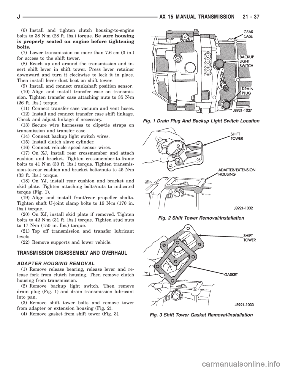
drain plug (Fig. 1) and drain transmission lubricant
into pan.
(3) Remove shift tower bolts and remove tower
from adapter or extension housing (Fig. 2).
(4) Remove gasket from shift tower (Fig. 3).
Fig. 1 Drain Plug And Backup Light Switch Location
Fig. 2 Shift Tower Removal/Installation
Fig. 3 Shift Tower Gasket Removal/Installation
JAX 15 MANUAL TRANSMISSION 21 - 37
Page 1603 of 2158
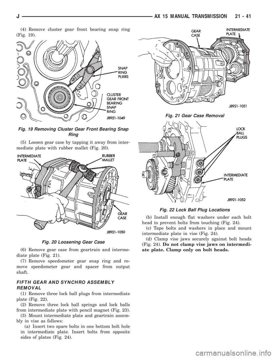
(4) Remove cluster gear front bearing snap ring
(Fig. 19).
(5) Loosen gear case by tapping it away from inter-
mediate plate with rubber mallet (Fig. 20).
(6) Remove gear case from geartrain and interme-
diate plate (Fig. 21).
(7) Remove speedometer gear snap ring and re-
move speedometer gear and spacer from output
shaft.
FIFTH GEAR AND SYNCHRO ASSEMBLY
REMOVAL
(1) Remove three lock ball plugs from intermediate
plate (Fig. 22).
(2) Remove three lock ball springs and lock balls
from intermediate plate with pencil magnet (Fig. 23).
(3) Mount intermediate plate and geartrain assem-
bly in vise as follows:
(a) Insert two spare bolts in one bottom bolt hole
in intermediate plate. Insert bolts from opposite
sides of plates (Fig. 24).(b) Install enough flat washers under each bolt
head to prevent bolts from touching (Fig. 24).
(c) Tape bolts and washers in place and mount
intermediate plate in vise (Fig. 24).
(d) Clamp vise jaws securely against bolt heads
(Fig. 24).Do not clamp vise jaws on intermedi-
ate plate. Clamp only on bolt heads.
Fig. 19 Removing Cluster Gear Front Bearing Snap
Ring
Fig. 20 Loosening Gear Case
Fig. 21 Gear Case Removal
Fig. 22 Lock Ball Plug Locations
JAX 15 MANUAL TRANSMISSION 21 - 41
Page 1604 of 2158
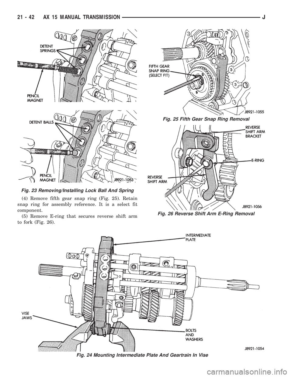
(4) Remove fifth gear snap ring (Fig. 25). Retain
snap ring for assembly reference. It is a select fit
component.
(5) Remove E-ring that secures reverse shift arm
to fork (Fig. 26).
Fig. 24 Mounting Intermediate Plate And Geartrain In Vise
Fig. 23 Removing/Installing Lock Ball And Spring
Fig. 25 Fifth Gear Snap Ring Removal
Fig. 26 Reverse Shift Arm E-Ring Removal
21 - 42 AX 15 MANUAL TRANSMISSIONJ
Page 1615 of 2158
FRONT BEARING/BEARING SEAL/REVERSE
SHAFT PIN INSTALLATION
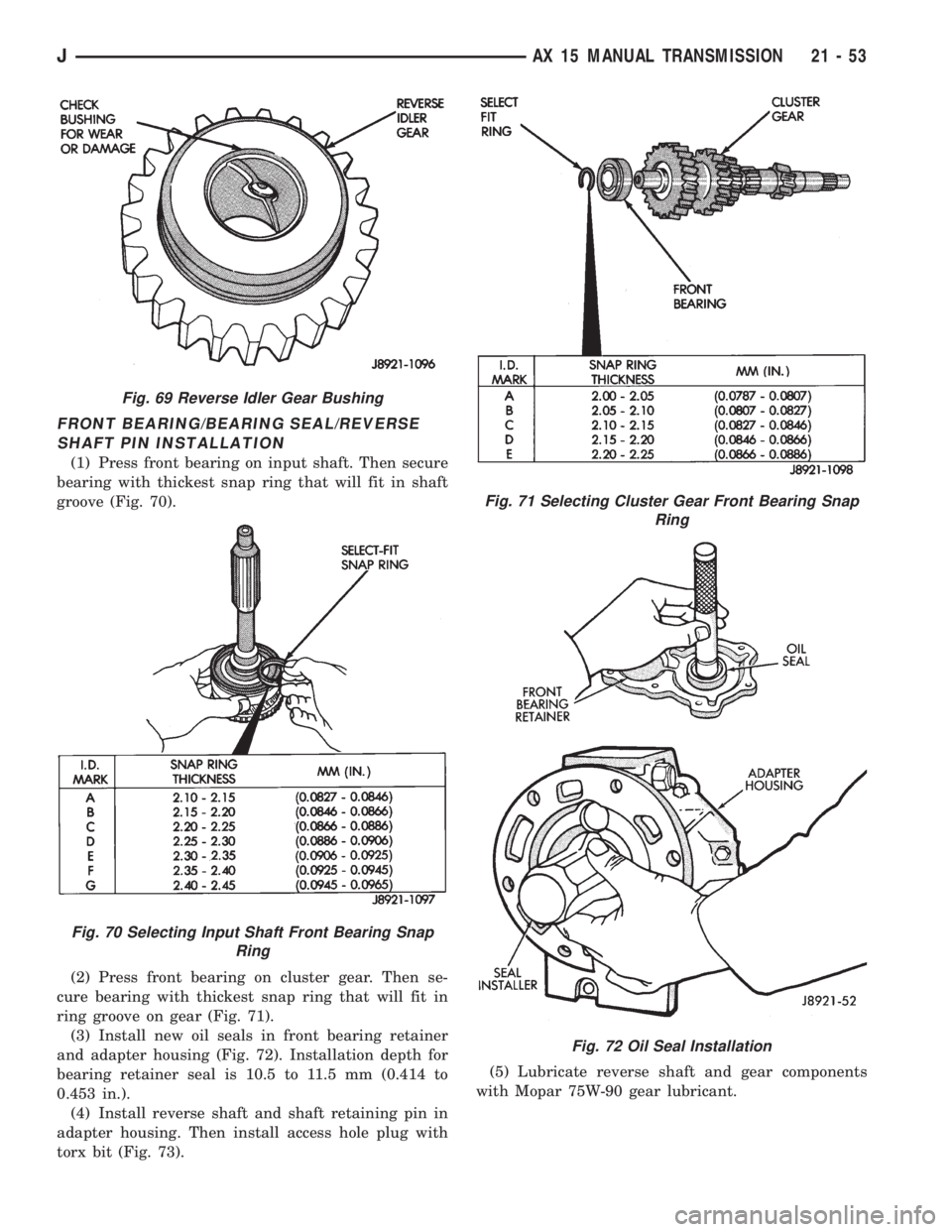
(1) Press front bearing on input shaft. Then secure
bearing with thickest snap ring that will fit in shaft
groove (Fig. 70).
(2) Press front bearing on cluster gear. Then se-
cure bearing with thickest snap ring that will fit in
ring groove on gear (Fig. 71).
(3) Install new oil seals in front bearing retainer
and adapter housing (Fig. 72). Installation depth for
bearing retainer seal is 10.5 to 11.5 mm (0.414 to
0.453 in.).
(4) Install reverse shaft and shaft retaining pin in
adapter housing. Then install access hole plug with
torx bit (Fig. 73).(5) Lubricate reverse shaft and gear components
with Mopar 75W-90 gear lubricant.
Fig. 69 Reverse Idler Gear Bushing
Fig. 70 Selecting Input Shaft Front Bearing Snap
Ring
Fig. 71 Selecting Cluster Gear Front Bearing Snap
Ring
Fig. 72 Oil Seal Installation
JAX 15 MANUAL TRANSMISSION 21 - 53
Page 1621 of 2158
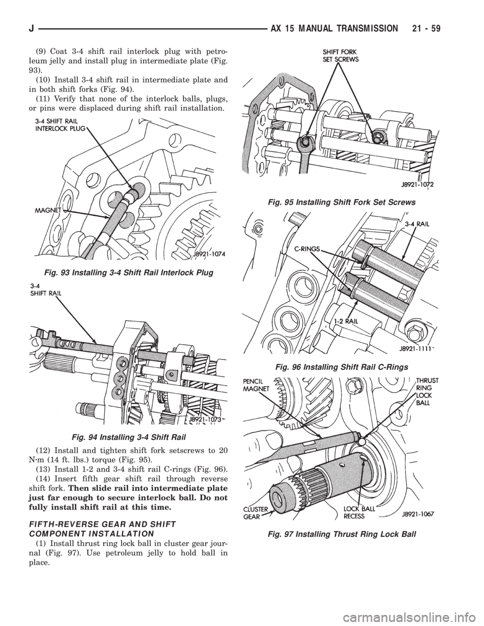
(9) Coat 3-4 shift rail interlock plug with petro-
leum jelly and install plug in intermediate plate (Fig.
93).
(10) Install 3-4 shift rail in intermediate plate and
in both shift forks (Fig. 94).
(11) Verify that none of the interlock balls, plugs,
or pins were displaced during shift rail installation.
(12) Install and tighten shift fork setscrews to 20
Nzm (14 ft. lbs.) torque (Fig. 95).
(13) Install 1-2 and 3-4 shift rail C-rings (Fig. 96).
(14) Insert fifth gear shift rail through reverse
shift fork.Then slide rail into intermediate plate
just far enough to secure interlock ball. Do not
fully install shift rail at this time.
FIFTH-REVERSE GEAR AND SHIFT
COMPONENT INSTALLATION
(1) Install thrust ring lock ball in cluster gear jour-
nal (Fig. 97). Use petroleum jelly to hold ball in
place.
Fig. 93 Installing 3-4 Shift Rail Interlock Plug
Fig. 94 Installing 3-4 Shift Rail
Fig. 95 Installing Shift Fork Set Screws
Fig. 96 Installing Shift Rail C-Rings
Fig. 97 Installing Thrust Ring Lock Ball
JAX 15 MANUAL TRANSMISSION 21 - 59