1995 JEEP XJ ECU
[x] Cancel search: ECUPage 1696 of 2158
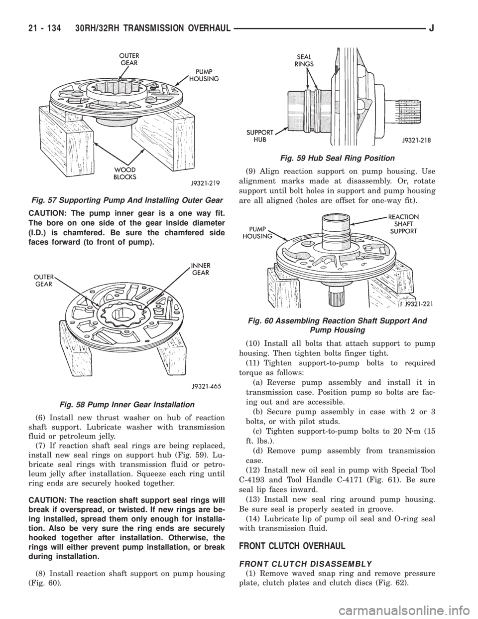
CAUTION: The pump inner gear is a one way fit.
The bore on one side of the gear inside diameter
(I.D.) is chamfered. Be sure the chamfered side
faces forward (to front of pump).
(6) Install new thrust washer on hub of reaction
shaft support. Lubricate washer with transmission
fluid or petroleum jelly.
(7) If reaction shaft seal rings are being replaced,
install new seal rings on support hub (Fig. 59). Lu-
bricate seal rings with transmission fluid or petro-
leum jelly after installation. Squeeze each ring until
ring ends are securely hooked together.
CAUTION: The reaction shaft support seal rings will
break if overspread, or twisted. If new rings are be-
ing installed, spread them only enough for installa-
tion. Also be very sure the ring ends are securely
hooked together after installation. Otherwise, the
rings will either prevent pump installation, or break
during installation.
(8) Install reaction shaft support on pump housing
(Fig. 60).(9) Align reaction support on pump housing. Use
alignment marks made at disassembly. Or, rotate
support until bolt holes in support and pump housing
are all aligned (holes are offset for one-way fit).
(10) Install all bolts that attach support to pump
housing. Then tighten bolts finger tight.
(11) Tighten support-to-pump bolts to required
torque as follows:
(a) Reverse pump assembly and install it in
transmission case. Position pump so bolts are fac-
ing out and are accessible.
(b) Secure pump assembly in case with 2 or 3
bolts, or with pilot studs.
(c) Tighten support-to-pump bolts to 20 Nzm (15
ft. lbs.).
(d) Remove pump assembly from transmission
case.
(12) Install new oil seal in pump with Special Tool
C-4193 and Tool Handle C-4171 (Fig. 61). Be sure
seal lip faces inward.
(13) Install new seal ring around pump housing.
Be sure seal is properly seated in groove.
(14) Lubricate lip of pump oil seal and O-ring seal
with transmission fluid.
FRONT CLUTCH OVERHAUL
FRONT CLUTCH DISASSEMBLY
(1) Remove waved snap ring and remove pressure
plate, clutch plates and clutch discs (Fig. 62).
Fig. 57 Supporting Pump And Installing Outer Gear
Fig. 58 Pump Inner Gear Installation
Fig. 59 Hub Seal Ring Position
Fig. 60 Assembling Reaction Shaft Support And
Pump Housing
21 - 134 30RH/32RH TRANSMISSION OVERHAULJ
Page 1699 of 2158
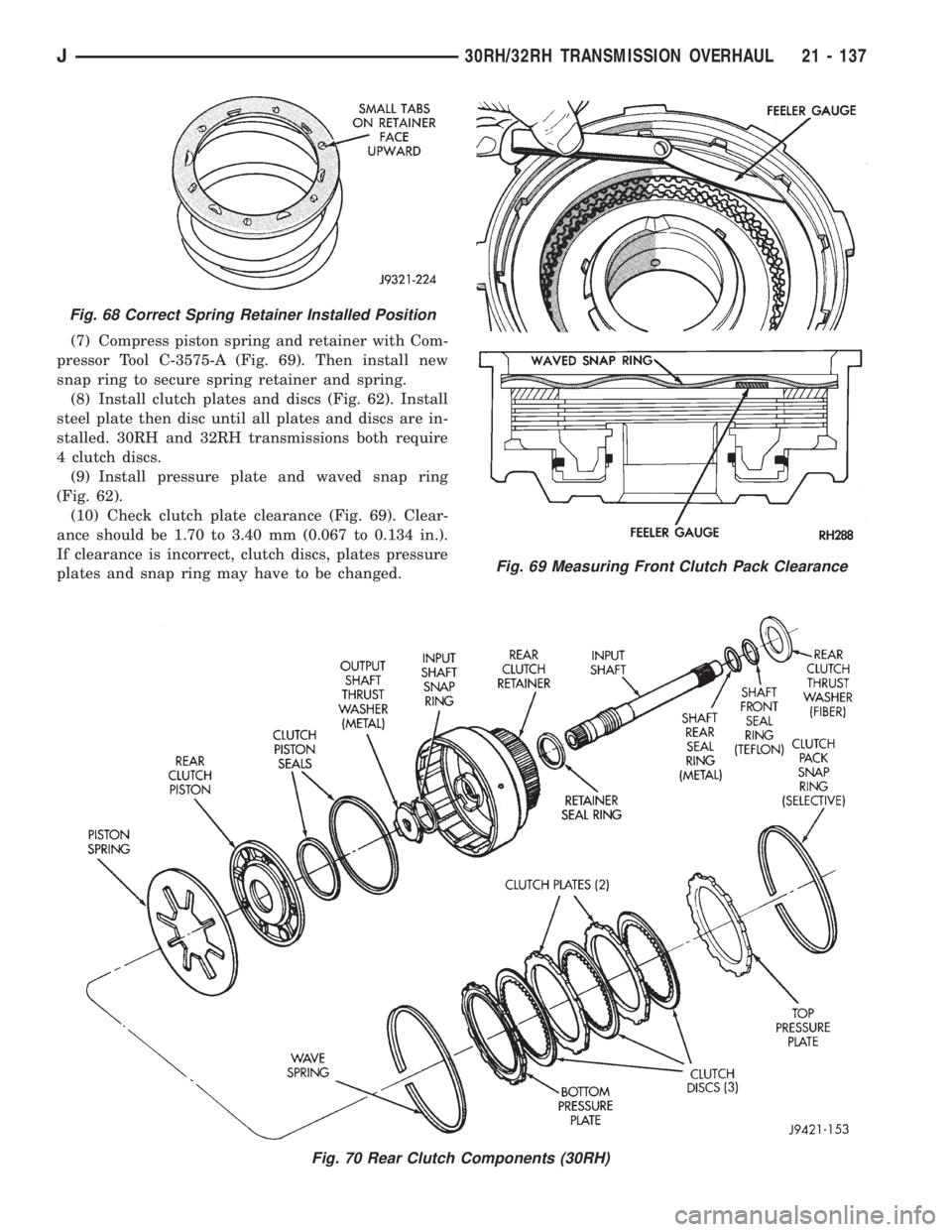
(7) Compress piston spring and retainer with Com-
pressor Tool C-3575-A (Fig. 69). Then install new
snap ring to secure spring retainer and spring.
(8) Install clutch plates and discs (Fig. 62). Install
steel plate then disc until all plates and discs are in-
stalled. 30RH and 32RH transmissions both require
4 clutch discs.
(9) Install pressure plate and waved snap ring
(Fig. 62).
(10) Check clutch plate clearance (Fig. 69). Clear-
ance should be 1.70 to 3.40 mm (0.067 to 0.134 in.).
If clearance is incorrect, clutch discs, plates pressure
plates and snap ring may have to be changed.
Fig. 70 Rear Clutch Components (30RH)
Fig. 68 Correct Spring Retainer Installed Position
Fig. 69 Measuring Front Clutch Pack Clearance
J30RH/32RH TRANSMISSION OVERHAUL 21 - 137
Page 1701 of 2158
Replace the retainer bushing if worn, scored, or
doubt exists about bushing condition.
Inspect the piston and retainer seal surfaces for
nicks or scratches. Minor scratches can be removed
with crocus cloth. However, replace the piston and/or
retainer if the seal surfaces are seriously scored.
Check condition of the fiber thrust washer and
metal output shaft thrust washer. Replace either
washer if worn or damaged.
Check condition of the seal rings on the input shaft
and clutch retainer hub. Replace the seal rings only
if worn, distorted, or damaged. The input shaft front
seal ring is teflon with chamfered ends. The rear ring
is metal with interlocking ends.
Check the input shaft for wear, or damage. Replace
the shaft if worn, scored or damaged in any way.
ASSEMBLING REAR CLUTCH
(1) Soak clutch discs in transmission fluid while
assembling other clutch parts.
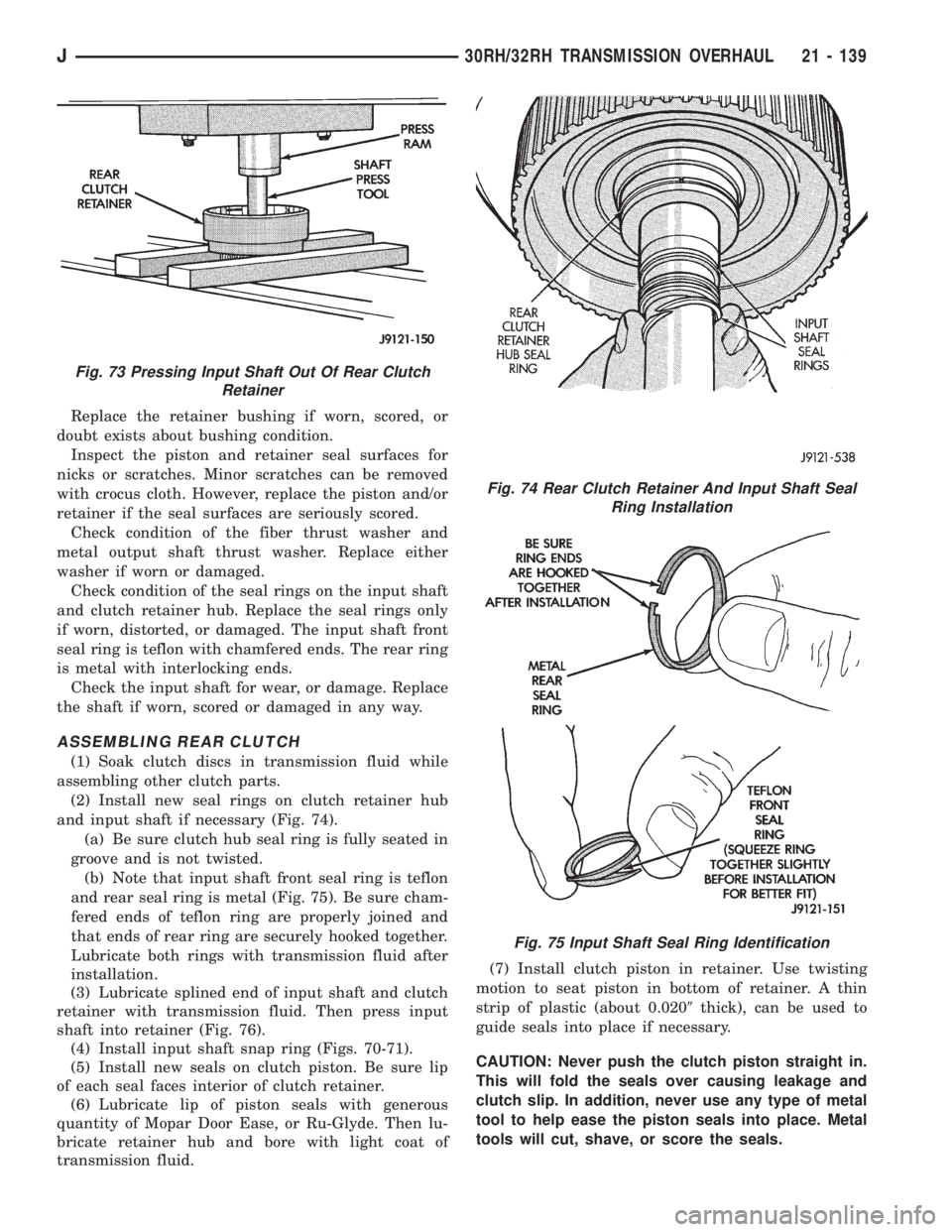
(2) Install new seal rings on clutch retainer hub
and input shaft if necessary (Fig. 74).
(a) Be sure clutch hub seal ring is fully seated in
groove and is not twisted.
(b) Note that input shaft front seal ring is teflon
and rear seal ring is metal (Fig. 75). Be sure cham-
fered ends of teflon ring are properly joined and
that ends of rear ring are securely hooked together.
Lubricate both rings with transmission fluid after
installation.
(3) Lubricate splined end of input shaft and clutch
retainer with transmission fluid. Then press input
shaft into retainer (Fig. 76).
(4) Install input shaft snap ring (Figs. 70-71).
(5) Install new seals on clutch piston. Be sure lip
of each seal faces interior of clutch retainer.
(6) Lubricate lip of piston seals with generous
quantity of Mopar Door Ease, or Ru-Glyde. Then lu-
bricate retainer hub and bore with light coat of
transmission fluid.(7) Install clutch piston in retainer. Use twisting
motion to seat piston in bottom of retainer. A thin
strip of plastic (about 0.0209thick), can be used to
guide seals into place if necessary.
CAUTION: Never push the clutch piston straight in.
This will fold the seals over causing leakage and
clutch slip. In addition, never use any type of metal
tool to help ease the piston seals into place. Metal
tools will cut, shave, or score the seals.
Fig. 73 Pressing Input Shaft Out Of Rear Clutch
Retainer
Fig. 74 Rear Clutch Retainer And Input Shaft Seal
Ring Installation
Fig. 75 Input Shaft Seal Ring Identification
J30RH/32RH TRANSMISSION OVERHAUL 21 - 139
Page 1710 of 2158
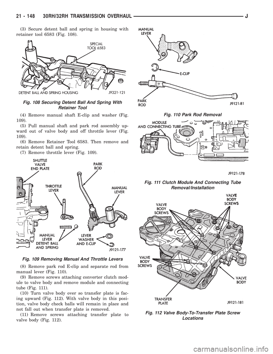
(3) Secure detent ball and spring in housing with
retainer tool 6583 (Fig. 108).
(4) Remove manual shaft E-clip and washer (Fig.
109).
(5) Pull manual shaft and park rod assembly up-
ward out of valve body and off throttle lever (Fig.
109).
(6) Remove Retainer Tool 6583. Then remove and
retain detent ball and spring.
(7) Remove throttle lever (Fig. 109).
(8) Remove park rod E-clip and separate rod from
manual lever (Fig. 110).
(9) Remove screws attaching converter clutch mod-
ule to valve body and remove module and connecting
tube (Fig. 111).
(10) Turn valve body over so transfer plate is fac-
ing upward (Fig. 112). With valve body in this posi-
tion, valve body check balls will remain in place and
not fall out when transfer plate is removed.
(11) Remove screws attaching transfer plate to
valve body (Fig. 112).
Fig. 108 Securing Detent Ball And Spring With
Retainer Tool
Fig. 109 Removing Manual And Throttle Levers
Fig. 110 Park Rod Removal
Fig. 111 Clutch Module And Connecting Tube
Removal/Installation
Fig. 112 Valve Body-To-Transfer Plate Screw
Locations
21 - 148 30RH/32RH TRANSMISSION OVERHAULJ
Page 1715 of 2158
VALVE BODY ASSEMBLY AND ADJUSTMENT
CAUTION: Do not force valves or plugs into place
during reassembly. If the valve body bores, valves
and plugs are free of distortion or burrs, the valve
body components should all slide into place easily.
In addition, do not overtighten the transfer plate
and valve body screws during reassembly. Over-
tightening can distort the valve body resulting in
valve sticking, cross leakage and unsatisfactory op-
eration. Tighten valve body screws to recom-
mended torque only.
(1) Lubricate valve body bores, valves and plugs
with Mopar ATF Plus transmission fluid.
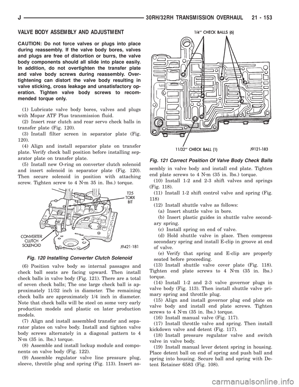
(2) Insert rear clutch and rear servo check balls in
transfer plate (Fig. 120).
(3) Install filter screen in separator plate (Fig.
120).
(4) Align and install separator plate on transfer
plate. Verify check ball position before installing sep-
arator plate on transfer plate.
(5) Install new O-ring on converter clutch solenoid
and insert solenoid in separator plate (Fig. 120).
Then secure solenoid in position with attaching
screw. Tighten screw to 4 Nzm 35 in. lbs.) torque.
(6) Position valve body so internal passages and
check ball seats are facing upward. Then install
check balls in valve body (Fig. 121). There are a total
of seven check balls; The one large check ball is ap-
proximately 11/32 inch in diameter. The remaining
check balls are approximately 1/4 inch in diameter.
Note that check balls will be steel on some very early
production models and plastic on later production
models.
(7) Align and install assembled transfer and sepa-
rator plates on valve body. Install and tighten valve
body screws alternately in a diagonal pattern to 4
Nzm (35 in. lbs.) torque.
(8) Assemble and install lockup module and compo-
nents on valve body (Fig. 122).
(9) Assemble regulator valve line pressure plug,
sleeve, throttle plug and spring (Fig. 113). Insert as-sembly in valve body and install end plate. Tighten
end plate screws to 4 Nzm (35 in. lbs.) torque.
(10) Install 1-2 and 2-3 shift valves and springs
(Fig. 118).
(11) Install 1-2 shift control valve and spring (Fig.
118)
(12) Install shuttle valve as follows:
(a) Insert shuttle valve in bore.
(b) Insert plastic guides in shuttle valve second-
ary spring.
(c) Install spring on end of valve.
(d) Hold shuttle valve in place. Then compress
secondary spring and install E-clip in groove at end
of valve.
(e) Verify that spring and E-clip are properly
seated before proceeding.
(13) Install shuttle valve cover plate (Fig. 118).
Tighten end plate screws to 4 Nzm (35 in. lbs.)
torque.
(14) Install 1-2 and 2-3 valve governor plugs in
valve body (Fig. 113). Then install shuttle valve pri-
mary spring and throttle plug.
(15) Align and install governor plug end plate on
valve body and install end plate screws. Tighten
screws to 4 Nzm (35 in. lbs.) torque.
(16) Install manual valve (Fig. 117).
(17) Install throttle valve and spring. Then install
kickdown valve and detent (Fig. 117).
(18) Install pressure regulator valve and switch
valve in valve body.
(19) Install manual lever detent spring in housing.
Place detent ball on end of spring and push ball and
spring into housing. Secure ball and spring with De-
tent Retainer 6583 (Fig. 108).
Fig. 120 Installing Converter Clutch Solenoid
Fig. 121 Correct Position Of Valve Body Check Balls
J30RH/32RH TRANSMISSION OVERHAUL 21 - 153
Page 1722 of 2158
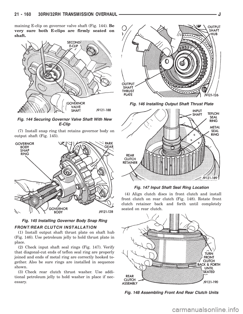
maining E-clip on governor valve shaft (Fig. 144).Be
very sure both E-clips are firmly seated on
shaft.
(7) Install snap ring that retains governor body on
output shaft (Fig. 145).
FRONT/REAR CLUTCH INSTALLATION
(1) Install output shaft thrust plate on shaft hub
(Fig. 146). Use petroleum jelly to hold thrust plate in
place.
(2) Check input shaft seal rings (Fig. 147). Verify
that diagonal-cut ends of teflon seal ring are properly
joined and ends of metal ring are correctly hooked to-
gether. Also be sure rings are installed in sequence
shown.
(3) Check rear clutch thrust washer. Use addi-
tional petroleum jelly to hold washer in place if nec-
essary.(4) Align clutch discs in front clutch and install
front clutch on rear clutch (Fig. 148). Rotate front
clutch retainer back and forth until completely
seated on rear clutch.
Fig. 144 Securing Governor Valve Shaft With New
E-Clip
Fig. 145 Installing Governor Body Snap Ring
Fig. 146 Installing Output Shaft Thrust Plate
Fig. 147 Input Shaft Seal Ring Location
Fig. 148 Assembling Front And Rear Clutch Units
21 - 160 30RH/32RH TRANSMISSION OVERHAULJ
Page 1726 of 2158
²On 32RH (4.0L), back adjusting screw off 2
1/4 turns
(d) Hold adjusting screw in position and tighten
locknut to 34 Nzm (25 ft. lbs.).
(2) Adjustrear bandas follows:
(a) Loosen locknut.
(b) Tighten adjusting screw as follows:
²On 32RH, tighten screw to 8 Nzm (72 in. lbs)
torque
²On 30RH, tighten screw to 5 Nzm (41 in. lbs.)
torque.
(c) Back off rear band adjusting screw as follows:
²On 30RH (2.5L), back adjusting screw off 7 turns
²On 32RH (4.0L), back adjusting screw off 4 turns
(d) Hold adjusting screw in place and tighten
locknut to 34 Nzm (25 ft. lbs.) torque.
(3) Install new pan gasket on transmission and in-
stall oil pan. Tighten pan bolts to 17 Nzm (13 ft. lbs.).(4) Turn transmission over.
EXTENSION HOUSING, CONTROL LEVER AND
CONVERTER INSTALLATION
(1) Install throttle valve and manual valve levers
on shaft.
(2) Position new extension adapter housing gasket
on transmission case. Use petroleum jelly to hold
gasket in place.
(3) Install new rear seal in extension housing if re-
quired.
(4) Install extension/adapter housing on transmis-
sion case. Tighten housing fasteners to 33 Nzm (24 ft.
lbs.). Be sure park lock rod is properly engaged in
sprag before tightening fasteners.
(5) Lubricate converter hub with transmission
fluid and carefully install converter. Turn converter
back and forth until seated.
(6) Secure converter in oil pump before mounting
transmission on jack and before moving transmission
back under vehicle. Use metal strapping, C-clamp, or
locking pliers to hold converter in place. Attach hold-
ing tool to converter housing.
CAUTION: The transmission cooler and lines must
be reverse flushed if overhaul corrected a malfunc-
tion that generated sludge, metal particles, or
clutch friction material. The torque converter and
drainback valve should also be replaced as they
will also be contaminated. Debris and residue NOT
flushed from the cooler and lines will flow back into
the transmission and converter. The result will be a
repeat failure and shop comeback.
Fig. 162 Fluid Filter Installation
21 - 164 30RH/32RH TRANSMISSION OVERHAULJ
Page 1745 of 2158
(6) Let engine run at normal curb idle speed, apply
service brakes. Then shift transmission through all
gear ranges and back to PARK (leave engine run-
ning).
(7) Remove dipstick and check fluid level. Add only
enough fluid to bring level to Full mark on dipstick.
Do not overfill.If too much fluid is added, excess
amount can be removed with suction gun and
plastic tubing. Tubing only has to be long
enough to extend into oil pan.
(8) When fluid level is correct, shut engine off, re-
lease park brake, remove funnel, and reseat dipstick
in fill tube.
TRANSMISSION CONTROL MODULE (TCM)
SERVICE
Use the DRB scan tool to diagnose transmission
control module function whenever a fault is sus-
pected. Replace the module only when the scan tool
indicates the module is actually faulty.
TRANSMISSION CONTROL MODULE
REPLACEMENT
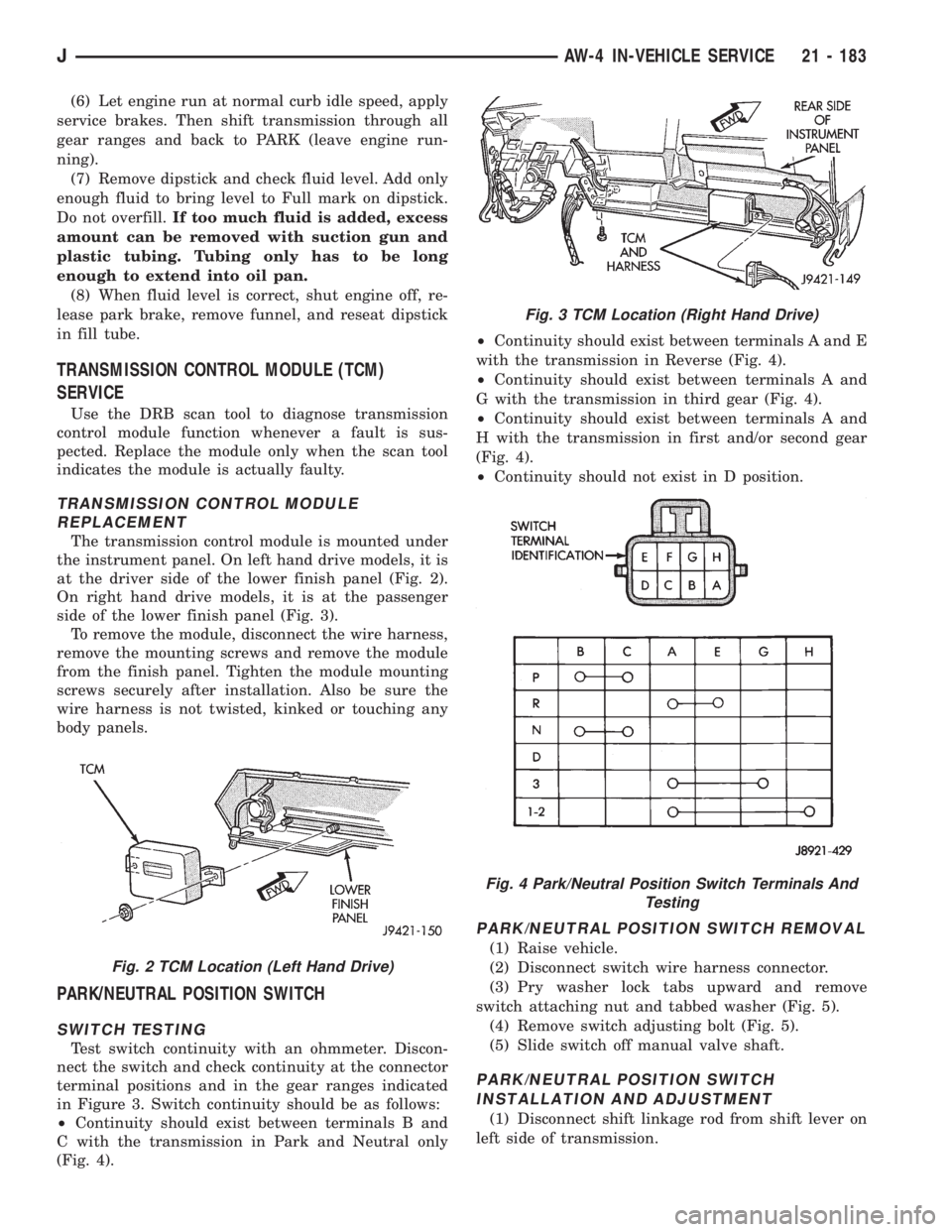
The transmission control module is mounted under
the instrument panel. On left hand drive models, it is
at the driver side of the lower finish panel (Fig. 2).
On right hand drive models, it is at the passenger
side of the lower finish panel (Fig. 3).
To remove the module, disconnect the wire harness,
remove the mounting screws and remove the module
from the finish panel. Tighten the module mounting
screws securely after installation. Also be sure the
wire harness is not twisted, kinked or touching any
body panels.
PARK/NEUTRAL POSITION SWITCH
SWITCH TESTING
Test switch continuity with an ohmmeter. Discon-
nect the switch and check continuity at the connector
terminal positions and in the gear ranges indicated
in Figure 3. Switch continuity should be as follows:
²Continuity should exist between terminals B and
C with the transmission in Park and Neutral only
(Fig. 4).²Continuity should exist between terminals A and E
with the transmission in Reverse (Fig. 4).
²Continuity should exist between terminals A and
G with the transmission in third gear (Fig. 4).
²Continuity should exist between terminals A and
H with the transmission in first and/or second gear
(Fig. 4).
²Continuity should not exist in D position.
PARK/NEUTRAL POSITION SWITCH REMOVAL
(1) Raise vehicle.
(2) Disconnect switch wire harness connector.
(3) Pry washer lock tabs upward and remove
switch attaching nut and tabbed washer (Fig. 5).
(4) Remove switch adjusting bolt (Fig. 5).
(5) Slide switch off manual valve shaft.
PARK/NEUTRAL POSITION SWITCH
INSTALLATION AND ADJUSTMENT
(1) Disconnect shift linkage rod from shift lever on
left side of transmission.
Fig. 2 TCM Location (Left Hand Drive)
Fig. 3 TCM Location (Right Hand Drive)
Fig. 4 Park/Neutral Position Switch Terminals And
Testing
JAW-4 IN-VEHICLE SERVICE 21 - 183