1995 JEEP XJ ECU
[x] Cancel search: ECUPage 2053 of 2158
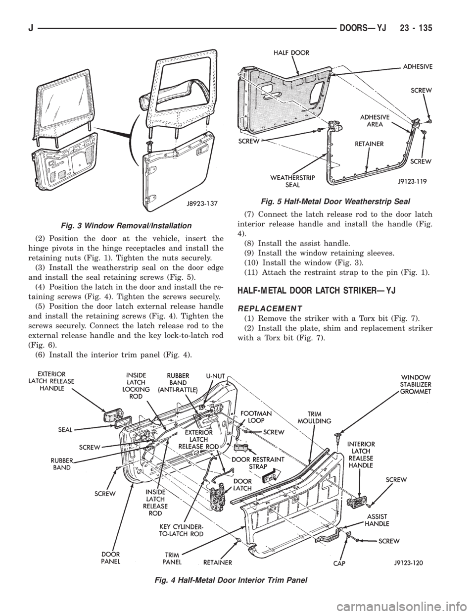
(2) Position the door at the vehicle, insert the
hinge pivots in the hinge receptacles and install the
retaining nuts (Fig. 1). Tighten the nuts securely.
(3) Install the weatherstrip seal on the door edge
and install the seal retaining screws (Fig. 5).
(4) Position the latch in the door and install the re-
taining screws (Fig. 4). Tighten the screws securely.
(5) Position the door latch external release handle
and install the retaining screws (Fig. 4). Tighten the
screws securely. Connect the latch release rod to the
external release handle and the key lock-to-latch rod
(Fig. 6).
(6) Install the interior trim panel (Fig. 4).(7) Connect the latch release rod to the door latch
interior release handle and install the handle (Fig.
4).
(8) Install the assist handle.
(9) Install the window retaining sleeves.
(10) Install the window (Fig. 3).
(11) Attach the restraint strap to the pin (Fig. 1).
HALF-METAL DOOR LATCH STRIKERÐYJ
REPLACEMENT
(1) Remove the striker with a Torx bit (Fig. 7).
(2) Install the plate, shim and replacement striker
with a Torx bit (Fig. 7).
Fig. 4 Half-Metal Door Interior Trim Panel
Fig. 3 Window Removal/Installation
Fig. 5 Half-Metal Door Weatherstrip Seal
JDOORSÐYJ 23 - 135
Page 2057 of 2158
(3) Slide the regulator arm guide onto the regula-
tor arm and position the guide on the window glass
(Fig. 12). Install the nuts, bushings and screws.
(4) Install the division channel lower adjustment
screw.
(5) Test the window glass for proper operation.
(6) Install the door waterdam and the trim panel
(Fig. 8 and 10).
FULL-METAL DOOR WINDOW GLASSÐYJ
ADJUSTMENT
One adjustment location provides amount of effort
required to raise and lower the door window glass.
The door window glass division channel is adjustable
fore and aft at the lower attaching location.
(1) Remove the door trim panel and the waterdam
(Fig. 8 and 10).
(2) Loosen channel lower adjustment screw and
move the division channel fore or aft to obtain the
desired door window glass operation.
Movement of the division channel fore or aft
will decrease or increase the free-play between
the channels.
(3) Tighten the division channel lower adjustment
screw.
(4) Install the door waterdam and the trim panel
(Fig. 8 and 10).
REMOVAL
(1) Remove the door trim panel and the waterdam
(Fig. 8 and 10).
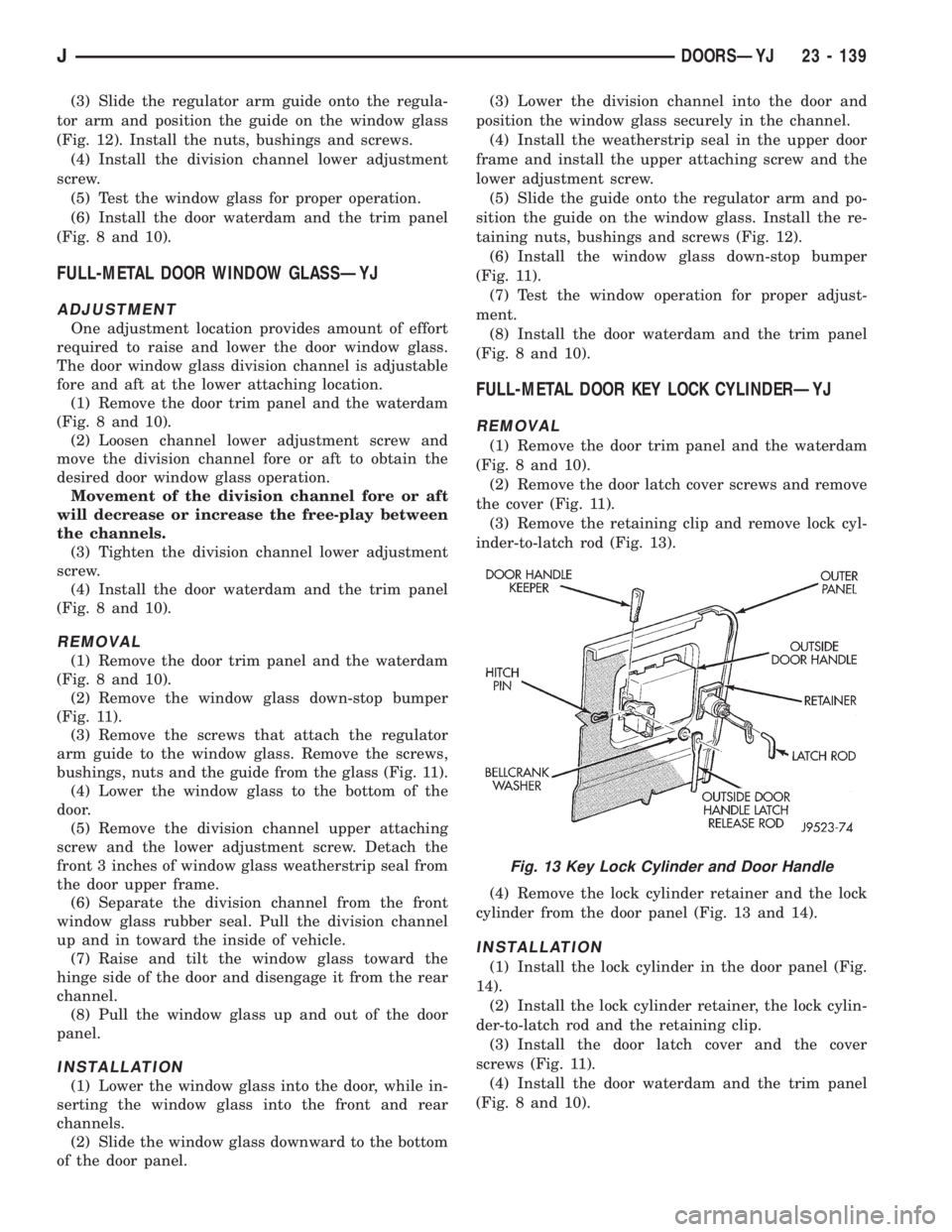
(2) Remove the window glass down-stop bumper
(Fig. 11).
(3) Remove the screws that attach the regulator
arm guide to the window glass. Remove the screws,
bushings, nuts and the guide from the glass (Fig. 11).
(4) Lower the window glass to the bottom of the
door.
(5) Remove the division channel upper attaching
screw and the lower adjustment screw. Detach the
front 3 inches of window glass weatherstrip seal from
the door upper frame.
(6) Separate the division channel from the front
window glass rubber seal. Pull the division channel
up and in toward the inside of vehicle.
(7) Raise and tilt the window glass toward the
hinge side of the door and disengage it from the rear
channel.
(8) Pull the window glass up and out of the door
panel.
INSTALLATION
(1) Lower the window glass into the door, while in-
serting the window glass into the front and rear
channels.
(2) Slide the window glass downward to the bottom
of the door panel.(3) Lower the division channel into the door and
position the window glass securely in the channel.
(4) Install the weatherstrip seal in the upper door
frame and install the upper attaching screw and the
lower adjustment screw.
(5) Slide the guide onto the regulator arm and po-
sition the guide on the window glass. Install the re-
taining nuts, bushings and screws (Fig. 12).
(6) Install the window glass down-stop bumper
(Fig. 11).
(7) Test the window operation for proper adjust-
ment.
(8) Install the door waterdam and the trim panel
(Fig. 8 and 10).
FULL-METAL DOOR KEY LOCK CYLINDERÐYJ
REMOVAL
(1) Remove the door trim panel and the waterdam
(Fig. 8 and 10).
(2) Remove the door latch cover screws and remove
the cover (Fig. 11).
(3) Remove the retaining clip and remove lock cyl-
inder-to-latch rod (Fig. 13).
(4) Remove the lock cylinder retainer and the lock
cylinder from the door panel (Fig. 13 and 14).
INSTALLATION
(1) Install the lock cylinder in the door panel (Fig.
14).
(2) Install the lock cylinder retainer, the lock cylin-
der-to-latch rod and the retaining clip.
(3) Install the door latch cover and the cover
screws (Fig. 11).
(4) Install the door waterdam and the trim panel
(Fig. 8 and 10).
Fig. 13 Key Lock Cylinder and Door Handle
JDOORSÐYJ 23 - 139
Page 2061 of 2158
(2) Position the door at the body opening, insert
the hinge pins in the hinge receptacles and install
the retaining nuts (Fig. 16). Tighten the nuts se-
curely.
(3) Install the weatherstrip seal on the door edge
(Fig. 18).
(4) Install the door outside handle and the keepers.
Connect the latch release rod to the handle (Fig. 13).
(5) Install the key lock cylinder (Fig. 14).
(6) Position the window glass in the channel and
the door.
(7) Attach the window glass to the regulator arm
guide (Fig. 12).
(8) Install the beltline weatherstrip seals in the
door (Fig. 18).
(9) Position the latch in the door and install the re-
taining screws (Fig. 15). Tighten the screws securely.
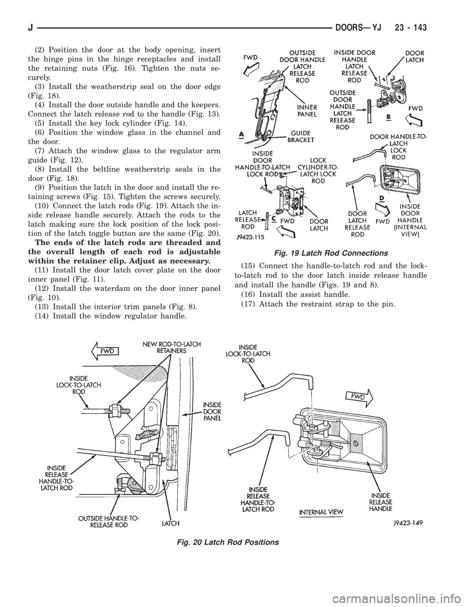
(10) Connect the latch rods (Fig. 19). Attach the in-
side release handle securely. Attach the rods to the
latch making sure the lock position of the lock posi-
tion of the latch toggle button are the same (Fig. 20).
The ends of the latch rods are threaded and
the overall length of each rod is adjustable
within the retainer clip. Adjust as necessary.
(11) Install the door latch cover plate on the door
inner panel (Fig. 11).
(12) Install the waterdam on the door inner panel
(Fig. 10).
(13) Install the interior trim panels (Fig. 8).
(14) Install the window regulator handle.(15) Connect the handle-to-latch rod and the lock-
to-latch rod to the door latch inside release handle
and install the handle (Figs. 19 and 8).
(16) Install the assist handle.
(17) Attach the restraint strap to the pin.
Fig. 19 Latch Rod Connections
Fig. 20 Latch Rod Positions
JDOORSÐYJ 23 - 143
Page 2070 of 2158
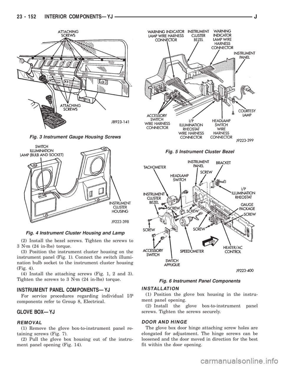
(2) Install the bezel screws. Tighten the screws to
3Nzm (24 in-lbs) torque.
(3) Position the instrument cluster housing on the
instrument panel (Fig. 1). Connect the switch illumi-
nation bulb socket to the instrument cluster housing
(Fig. 4).
(4) Install the attaching screws (Fig. 1, 2 and 3).
Tighten the screws to 3 Nzm (24 in-lbs) torque.
INSTRUMENT PANEL COMPONENTSÐYJ
For service procedures regarding individual I/P
components refer to Group 8, Electrical.
GLOVE BOXÐYJ
REMOVAL
(1) Remove the glove box-to-instrument panel re-
taining screws (Fig. 7).
(2) Pull the glove box housing out of the instru-
ment panel opening (Fig. 14).
INSTALLATION
(1) Position the glove box housing in the instru-
ment panel opening.
(2) Install the glove box-to-instrument panel
screws. Tighten the screws securely.
DOOR AND HINGE
The glove box door hinge attaching screw holes are
elongated for adjustment. The hinge screws can be
loosened and the door moved in direction for the best
fit within the door opening.
Fig. 3 Instrument Gauge Housing Screws
Fig. 4 Instrument Cluster Housing and Lamp
Fig. 5 Instrument Cluster Bezel
Fig. 6 Instrument Panel Components
23 - 152 INTERIOR COMPONENTSÐYJJ
Page 2071 of 2158
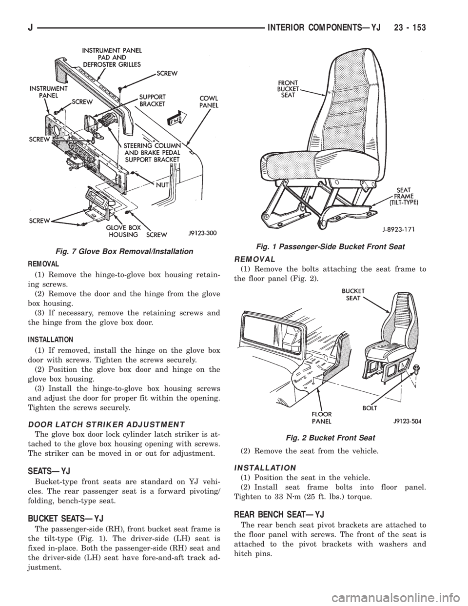
REMOVAL
(1) Remove the hinge-to-glove box housing retain-
ing screws.
(2) Remove the door and the hinge from the glove
box housing.
(3) If necessary, remove the retaining screws and
the hinge from the glove box door.
INSTALLATION
(1) If removed, install the hinge on the glove box
door with screws. Tighten the screws securely.
(2) Position the glove box door and hinge on the
glove box housing.
(3) Install the hinge-to-glove box housing screws
and adjust the door for proper fit within the opening.
Tighten the screws securely.
DOOR LATCH STRIKER ADJUSTMENT
The glove box door lock cylinder latch striker is at-
tached to the glove box housing opening with screws.
The striker can be moved in or out for adjustment.
SEATSÐYJ
Bucket-type front seats are standard on YJ vehi-
cles. The rear passenger seat is a forward pivoting/
folding, bench-type seat.
BUCKET SEATSÐYJ
The passenger-side (RH), front bucket seat frame is
the tilt-type (Fig. 1). The driver-side (LH) seat is
fixed in-place. Both the passenger-side (RH) seat and
the driver-side (LH) seat have fore-and-aft track ad-
justment.
REMOVAL
(1) Remove the bolts attaching the seat frame to
the floor panel (Fig. 2).
(2) Remove the seat from the vehicle.
INSTALLATION
(1) Position the seat in the vehicle.
(2) Install seat frame bolts into floor panel.
Tighten to 33 Nzm (25 ft. lbs.) torque.
REAR BENCH SEATÐYJ
The rear bench seat pivot brackets are attached to
the floor panel with screws. The front of the seat is
attached to the pivot brackets with washers and
hitch pins.
Fig. 7 Glove Box Removal/InstallationFig. 1 Passenger-Side Bucket Front Seat
Fig. 2 Bucket Front Seat
JINTERIOR COMPONENTSÐYJ 23 - 153
Page 2113 of 2158
INSTALLATION
(1) Install the cables to the heater control panel.
(2) Connect right vent door cable. DO NOT connect
the left door cable at this time.
(3) Open and close the right vent door (one time)
using the air control lever on the heater control
panel.
(4) Connect left vent door cable.
(5) Open and close both vent doors with the air
control lever. Verify that both vent doors open at the
same time.
HEATER CORE AND HOUSING
REVIEW ALL WARNINGS AND CAUTIONS IN
THIS GROUP BEFORE PERFORMING THIS
OPERATION.
REMOVAL
(1) Drain coolant from the radiator.
(2) Disconnect heater hoses.
(3) Disconnect vent door cables.
(4) Disconnect blower motor wire.
(5) Disconnect defroster duct.
(6) Remove nuts that attach the heater housing
studs to the engine compartment side of the dash
panel.
(7) Remove heater housing assembly by tilting it
downward, to disengage it from the defroster duct.
Pull it rearward and out from under the instrument
panel.
(8) Remove heater hosing cover from the housing.
(9) Remove heater core from the housing.
INSTALLATION
(1) Install the heater core into the housing and in-
stall the cover on the housing.
(2) Position heater housing on the dash panel. Be
sure the housing studs all extend through the dash
panel.
(3) Install the seals on the heater core outlet and
inlet tubes and over the blower motor housing.
(4) Install attaching nuts on the housing studs.
CAUTION: DO NOT over tighten the attaching nuts.
The housing could become distorted causing air
leaks and improper heater door operation. Tighten
the nuts alternately and evenly until 2 stud threads
are visible beyond each nut.
(5) Connect defroster duct to the housing.
(6) Connect blower motor wire.
(7) Connect vent door control cables.
(8) Connect heater hoses.
(9) Fill cooling system.
(10) Check system operation.
BLOWER MOTOR (HEATING)
REMOVAL
(1) Remove heater housing.
(2) Remove blower motor-to-heater housing attach-
ing screws/nuts.
(3) Remove blower motor from the housing.
INSTALLATION
(1) Position blower motor into housing.
(2) Install and tighten blower motor-to-heater
housing attaching screws/nuts.
(3) Install heater housing.
(4) Check blower motor and heater operation.
DEFROSTER NOZZLE AND DUCT
REVIEW ALL WARNINGS AND CAUTIONS IN
THIS GROUP BEFORE PERFORMING THIS
OPERATION.
REMOVAL
(1) Drain coolant from the radiator.
(2) Disconnect heater hoses.
(3) Remove nuts attaching the heater housing
studs to the engine compartment side of the dash
panel.
(4) Disconnect speedometer cable.
(5) Remove glove box.
(6) Tilt heater housing back and pull it rearward
and out from under the instrument panel.
(7) Disconnect vent control cables.
(8) Remove fresh air intake grille from the cowl.
(9) Remove fresh air intake duct.
(10) Lower windshield.
(11) Remove defroster nozzle attaching screws and
remove the nozzle and duct.
INSTALLATION
(1) Install defroster nozzle and duct.
(2) Raise and secure the windshield.
(3) Install fresh air intake duct.
(4) Install fresh air intake grille on the cowl.
(5) Install vent cables.
(6) Position heater housing on the dash panel. Be
sure all the housing studs extend through the dash
panel.
(7) Install seals on the blower motor and heater
core inlet and outlet tubes.
(8) Install on the housing studs.
CAUTION: DO NOT over tighten the attaching nuts.
The housing could become distorted causing air
leaks and improper heater door operation. Tighten
the nuts alternately and evenly until 2 stud threads
are visible beyond each nut.
(9) Install glove box.
(10) Connect speedometer cable.
JHEATING AND AIR CONDITIONING 24 - 33
Page 2114 of 2158
(11) Connect the heater hoses.
(12) Fill cooling system.
FRESH AIR DOOR VACUUM MOTOR
REMOVAL
(1) Remove glove box and assist handle.
(2) Disconnect vacuum hose from the motor.
(3) Remove motor lever retaining clip.
(4) Remove motor attaching nuts and remove the
motor from the fresh air duct.
INSTALLATION
(1) Position motor on fresh air duct and install the
motor attaching nuts.
(2) Align motor lever with the air door lever and
install the lever retaining clip.
(3) Connect vacuum hose to the motor.
(4) Install glove box and assist handle.
FRESH AIR INTAKE DUCT
REVIEW WARNINGS AND CAUTIONS IN
THIS GROUP BEFORE PERFORMING THIS
OPERATION.
REMOVAL
(1) Drain coolant from the radiator.
(2) Disconnect heater hoses.
(3) Remove nuts attaching the heater housing
studs to the dash panel from inside the engine com-
partment.
(4) Disconnect speedometer cable.
(5) Remove glove box and assist handle.
(6) Tilt heater housing back and pull it rearward
and out from under the instrument panel.
(7) Disconnect vent cables.
(8) Remove windshield bracket bolts and lower
windshield.
(9) Remove fresh air intake grille from the cowl.
(10) Remove fresh air intake duct.
INSTALLATION
(1) Install fresh air intake duct.
(2) Install defroster nozzle and duct.
(3) Raise and secure the windshield.
(4) Install fresh air grille on the cowl.
(5) Install vent cables.
(6) Position heater housing on the dash panel. Be
sure all the housing studs extend through the dash
panel.
(7) Install seals on the blower motor and heater
core inlet and outlet tubes.
(8) Install nuts on the heater housing studs.
CAUTION: DO NOT over tighten the attaching nuts.
The housing could become distorted causing air
leaks and improper heater door operation. Tightenthe nuts alternately and evenly until 2 stud threads
are visible beyond each nut.
(9) Install glove box and assist handle.
(10) Connect speedometer cable.
(11) Connect heater hoses.
(12) Fill cooling system.
TEMPERATURE CONTROL THERMOSTAT
REMOVAL
(1) Remove mounting bolts and lower the evapora-
tor housing.
(2) Remove the attaching screws holding the top
and bottom housings together.
(3) Separate the housings.
(4) Remove the thermostat.
INSTALLATION
(1) Install temperature control thermostat. Insert
thermostat capillary tube into the evaporator coil a
minimum of 50 mm (2 inch).
CAUTION: Handle the tube with care to avoid bends
or kinks that could cause the thermostat to mal-
function.
(2) Assemble the housing and install the attaching
screws. DO NOT over tighten the attaching screws.
(3) Install the evaporator housing.
A/C CONDENSER
REVIEW WARNINGS AND CAUTIONS IN
THIS GROUP BEFORE PERFORMING THIS
OPERATION.
REMOVAL
(1) Recover refrigerant from A/C system.
(2) Drain the radiator.
(3) Remove fan shroud and radiator.
(4) Disconnect A/C line from the condenser.
(5) Remove condenser attaching screws and tilt the
bottom of the condenser toward the engine.Plug all
the condenser openings to prevent entry of dirt
or moisture.
(6) Working from under the vehicle, disconnect the
receiver-drier to-evaporator hose fitting from the re-
ceiver-drier.
(7) Remove condenser and receiver-drier as an as-
sembly.
(8) Remove receiver-drier from the condenser, if
necessary.
INSTALLATION
Add 30 ml (1 fluid oz.) of refrigerant oil to the A/C
system if the condenser is replaced.
(1) Attach receiver-drier to the condenser.
(2) Install condenser and connect A/C line to the
receiver-drier.
24 - 34 HEATING AND AIR CONDITIONINGJ
Page 2115 of 2158
(3) Install condenser attaching screws.
(4) Connect condenser A/C line.
(5) Install radiator and fan shroud.
(6) Fill coolant system (Refer to cooling for proper
procedure).
(7) Evacuate, charge and leak test the air condi-
tioning system.
RECEIVER-DRIER REPLACEMENT
REVIEW ALL WARNINGS AND CAUTIONS IN
THIS GROUP BEFORE PERFORMING THIS
OPERATION.
REMOVAL
(1) Recover refrigerant from A/C system.
(2) Disconnect A/C lines from the receiver-drier.
(3) Remove receiver-drier attaching screws and re-
move receiver-drier.
INSTALLATION
(1) Position receiver-drier in place and install re-
ceiver-drier attaching screws.
(2) Connect A/C lines to receiver-drier.
(3) Evacuate, charge and leak test the air condi-
tioning system.
EVAPORATOR AND HOUSING
REVIEW ALL WARNINGS AND CAUTIONS IN
THIS GROUP BEFORE PERFORMING THIS
OPERATION.
REMOVAL
(1) Recover refrigerant from A/C system.
(2) Disconnect A/C lines.
(3) Remove hose clamps and dash grommet retain-
ing screws.
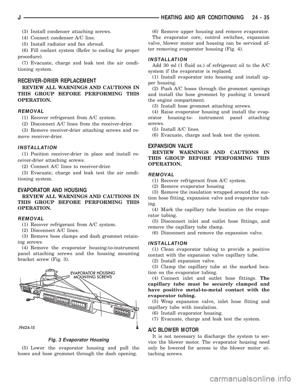
(4) Remove the evaporator housing-to-instrument
panel attaching screws and the housing mounting
bracket screw (Fig. 3).
(5) Lower the evaporator housing and pull the
hoses and hose grommet through the dash opening.(6) Remove upper housing and remove evaporator.
The evaporator core, control switches, expansion
valve, blower motor and housing can be serviced af-
ter removing evaporator housing (Fig. 4).
INSTALLATION
Add 30 ml (1 fluid oz.) of refrigerant oil to the A/C
system if the evaporator is replaced.
(1) Install evaporator into housing and install up-
per housing.
(2) Push A/C hoses through the grommet openings
and install the hose grommet by pushing it toward
the engine compartment.
(3) Install hose grommet attaching screws.
(4) Raise evaporator housing and install the evap-
orator housing-to- instrument panel attaching
screws.
(5) Install A/C lines.
(6) Evacuate, charge and leak test the system.
EXPANSION VALVE
REVIEW WARNINGS AND CAUTIONS IN
THIS GROUP BEFORE PERFORMING THIS
OPERATION.
REMOVAL
(1) Recover refrigerant from A/C system.
(2) Remove evaporator housing
(3) Remove the insulation wrapped around the suc-
tion hose fitting, expansion valve and evaporator tub-
ing.
(4) Mark the capillary tube location on the evapo-
rator tubing.
(5) Disconnect inlet and outlet hose fittings, and
remove the capillary tube clamp.
(6) Disconnect and remove the expansion valve.
INSTALLATION
(1) Clean evaporator tubing to provide a positive
contact with the expansion valve capillary tube.
(2) Install expansion valve.
(3) Clamp the capillary tube at the marked loca-
tion on the evaporator tubing.
(4) Connect inlet and outlet hose fittings.The
capillary tube must be securely clamped and
have positive metal-to-metal contact with the
evaporator tubing.
(5) Wrap expansion valve, inlet hose fitting and
capillary tube with insulation.
(6) Install evaporator housing.
(7) Evacuate, charge and leak test the system.
A/C BLOWER MOTOR
It is not necessary to discharge the system to ser-
vice the blower motor. The evaporator housing need
only be lowered for access to the blower motor at-
taching screws.Fig. 3 Evaporator Housing
JHEATING AND AIR CONDITIONING 24 - 35