1995 JEEP CHEROKEE Oil Pressure Sensor
[x] Cancel search: Oil Pressure SensorPage 1992 of 2198
TROUBLESHOOTING TOOLS; WIRING
DIAGRAMSÐGENERAL INFORMATION
(XJ)...............................8W-4
TROUBLESHOOTING WIRING
PROBLEMS; WIRING DIAGRAMSÐ
GENERAL INFORMATION (XJ)...........8W-5
TUBE AXLE (2WD), MODEL 30 AXLE......2-22
TUBE CAP, FUEL TANK FILLER;
EMISSION CONTROL SYSTEMS......25-4,25-7
TUBE CAP, FUEL TANK FILLER; FUEL
SYSTEM............................14-13
TUBE, NO-LEAD FUEL TANK FILLER......14-13
TUBES/LINES/HOSES AND CLAMPS,
FUEL..........................14-62,14-9
TURN RELAY, LEFT; TRAILER TOW (XJ) . 8W-54-1
TURN RELAY, LEFT; TRAILER TOW
(XJ-RHD).........................8W-54-1
TURN RELAY, RIGHT; TRAILER TOW
(XJ).............................8W-54-1
TURN RELAY, RIGHT; TRAILER TOW
(XJ-RHD).........................8W-54-1
TURN SIGNAL INDICATOR LAMPS;
INSTRUMENT CLUSTER (XJ).........8W-40-2
TURN SIGNAL INDICATOR LAMPS;
INSTRUMENT CLUSTER (XJ-RHD).....8W-40-2
TURN SIGNAL RELAY; TURN SIGNALS
(XJ-RHD).........................8W-52-1
TURN SIGNAL SYSTEM.................8J-1
TURN SIGNAL SYSTEM - YJ.............8J-3
TURN SIGNAL/HAZARD WARNING
SWITCH REMOVE/INSTALL - YJ..........8J-5
TURN SIGNAL/HAZARD WARNING
SYSTEM - XJ..........................8J-3
TURN SIGNALS; TURN SIGNALS (YJ) . . 8W-52-1
TURN SIGNAL/TAIL LAMP BULB
REPLACEMENTÐXJ, BACK-UP/REAR.....8L-12
TURN SIGNAL/TAIL LAMP BULB
REPLACEMENTÐYJ, BACK-UP/REAR.....8L-28
TWO-WHEEL-DRIVE VEHICLE TOWINGÐ
XJ .................................0-11
U-JOINTS, PROPELLER SHAFTS.........16-15
UNBALANCE.........................16-3
UNDERHOOD LAMP; INTERIOR
LIGHTING (XJ)....................8W-44-2
UNDERHOOD LAMP; INTERIOR
LIGHTING (XJ-RHD)................8W-44-1
UNDERHOOD LAMP; INTERIOR
LIGHTING (YJ)....................8W-44-1
UNDERHOOD LAMP BULB
REPLACEMENTÐXJ..................8L-13
UNDERHOOD LAMP BULB
REPLACEMENTÐYJ..................8L-29
UNDERHOOD LAMP REPLACEMENTÐXJ . . 8L-13
UNDERHOOD LAMP REPLACEMENTÐYJ . . 8L-29
UNDERHOOD LAMP SERVICE
INFORMATIONÐXJ...................8L-12
UNDERHOOD LAMP SERVICE
INFORMATIONÐYJ...................8L-28
UNIT (ECU), ELECTRONIC CONTROL......5-34
UNIT, FUEL GAUGE SENDING...........14-16
UNIT (HCU), HYDRAULIC CONTROL.......5-33
UNIT, HYDRAULIC CONTROL; ANTI-LOCK
BRAKES (XJ)......................8W-32-2
UNIT, HYDRAULIC CONTROL; ANTI-LOCK
BRAKES (XJ-RHD).................8W-32-2
UNIT, HYDRAULIC CONTROL; ANTI-LOCK
BRAKES (YJ)......................8W-32-2
UNIVERSAL JOINT ANGLE
MEASUREMENT.......................16-4
UNIVERSAL JOINT REPLACEMENT.......16-10
UNIVERSAL JOINTS...................16-2
UNLOCK RELAY; POWER DOOR LOCKS
(XJ).............................8W-61-1
UNLOCK RELAY; POWER DOOR LOCKS
(XJ-RHD).........................8W-61-1
UPPER SUSPENSION ARM..............2-12
UPSHIFT LAMP; FUEL/IGNITION (XJ) . . . 8W-30-5
UP-SHIFT LAMP; INSTRUMENT CLUSTER
(YJ)
.............................8W-40-2
UPSHIFT LAMP; TRANSMISSION
CONTROLS (XJ)
...................8W-31-1
UPSHIFT LAMP; TRANSMISSION
CONTROLS (YJ)
...................8W-31-1
UP-SHIFT LAMP, MANUAL
TRANSMISSION; INSTRUMENT
CLUSTER (XJ)
.....................8W-40-2
USAGE, INSTALLATION METHODS AND
PARTS
...............................6-4USAGE STATEMENT, FUEL...............14-1
USAGE STATEMENTÐGAS ENGINES,
FUEL...............................0-19
USE THIS GROUP, HOW TO; WIRING
DIAGRAMS (XJ)......................8W-1
USE THIS GROUP, HOW TO; WIRING
DIAGRAMS (XJ-RHD)..................8W-1
USE THIS GROUP, HOW TO; WIRING
DIAGRAMS (YJ)......................8W-1
USING ALIGNMENT SCREENÐXJ,
HEADLAMP/FOG LAMP ADJUSTMENT.....8L-7
USING ALIGNMENT SCREENÐYJ,
HEADLAMP/FOG LAMP ADJUSTMENT....8L-23
USING ON-BOARD DIAGNOSTIC
SYSTEM; BATTERY/STARTING/
CHARGING SYSTEMS DIAGNOSTICS.....8A-22
USING ON-BOARD DIAGNOSTIC
SYSTEM; VEHICLE SPEED CONTROL
SYSTEM............................8H-5
VACUUM DISCONNECT AXLEÐYJ
VEHICLES...........................2-27
VACUUM HOSE ROUTING SCHEMATICS....25-2
VACUUM MOTOR, FRESH AIR DOOR.....24-34
VACUUM MOTOR REPLACEMENT, A/C
RECIRCULATING DOOR................24-27
VACUUM MOTOR REPLACEMENT,
HEATER/DEFROSTER/INSTRUMENT
PANEL OUTLET......................24-26
VACUUM RESERVOIR..................8H-1
VACUUM RESERVOIR REMOVE/INSTALL . . 8H-10
VACUUM ROUTING SCHEMATICÐ2.5L 4
CYLINDER ENGINE....................25-3
VACUUM ROUTING SCHEMATICÐ4.0L 6
CYLINDER ENGINE....................25-3
VACUUM SUPPLY TEST................8H-6
VACUUM TEST, POWER BOOSTER.........5-9
VALUES, CONVERSION FORMULAS AND
EQUIVALENT......................Intro.-11
VALVE AND SPRING IDENTIFICATION,
AW-4 .............................21-343
VALVE BODY ASSEMBLY AND
ADJUSTMENT......................21-153
VALVE BODY CHECK BALL DIMENSIONS,
AW-4 .............................21-341
VALVE BODY DISASSEMBLY AND
INSPECTION.......................21-147
VALVE BODY INSTALLATION,
TRANSMISSION.....................21-187
VALVE BODY OVERHAUL,
TRANSMISSION.....................21-250
VALVE BODY REMOVAL, TRANSMISSION . 21-186
VALVE BODY SERVICE...............21-104
VALVE BODY SOLENOIDS,
TRANSMISSION.....................21-184
VALVE CABLE ADJUSTMENT,
TRANSMISSION THROTTLE............21-71
VALVE CABLE ADJUSTMENT (XJ/YJ),
THROTTLE.........................21-101
VALVE COMPONENT REPLACEÐ
CYLINDER HEAD NOT REMOVED.....9-23,9-65
VALVE, EXPANSION..............24-31,24-35
VALVE FITTING O-RING SEAL, FLOW
CONTROL..........................19-14
VALVE, FUEL TANK PRESSURE
RELIEF/ROLLOVER..............14-16,14-62
VALVE INSTALLATION (WITH ABS),
MASTER CYLINDER AND
COMBINATION........................5-20
VALVE, MASTER CYLINDERÐ
COMBINATION
........................5-15
VALVE, PRESSURE RELIEF/ROLLOVER
. 25-6,25-7
VALVE REMOVAL (WITH ABS), MASTER
CYLINDER AND COMBINATION
...........5-17
VALVE REPLACEMENT (NON-ABS),
COMBINATION
........................5-16
VALVE SERVICE, CONVERTER
DRAINBACK CHECK
..................21-113
VALVE SHAFT OVERHAUL, MANUAL
.....21-215
VALVE SHAFT SEAL REPLACEMENT,
MANUAL
..........................21-187
VALVE SPRINGS AND OIL SEALS
.........9-23
VALVE SPRINGS, VALVES
...........9-27,9-69
VALVE STEM SEAL AND SPRING
REPLACEMENT
.......................9-65
VALVE TEST, POWER BOOSTER CHECK
.....5-9
VALVE TIMING
....................9-30,9-71
VALVES AND VALVE SPRINGS
.......9-27,9-69VANITY MIRROR LAMPS, VISOR;
INTERIOR LIGHTING (XJ)............8W-44-2
VANITY MIRROR LAMPS, VISOR;
INTERIOR LIGHTING (XJ-RHD)........8W-44-1
VANITY MIRROR TROUBLE
DIAGNOSISÐXJ, LIGHTED.............8L-16
VANITY MIRRORÐXJ, LIGHTED.........8L-16
VARIANCE, PINION GEAR DEPTH; FRONT
SUSPENSION AND AXLE................2-40
VARIANCE, PINION GEAR DEPTH; REAR
SUSPENSION AND AXLES...........3-22,3-39
VARIATION ADJUSTMENT, COMPASS......8C-5
VARIATION, DISC BRAKE ROTOR
THICKNESS..........................5-52
VEHICLE CODE DECODING............Intro.-5
VEHICLE CODE DESIGNATIONS........Intro.-1
VEHICLE CODE PLATE...............Intro.-4
VEHICLE CONTROL AND DISPLAY
SYMBOLS........................Intro.-10
VEHICLE CONTROL AND DISPLAY
SYMBOLS, INTERNATIONAL...........Intro.-5
VEHICLE DESIGNATIONS.............Intro.-1
VEHICLE DIMENSION DATA.....Intro.-5,Intro.-6
VEHICLE EMISSION CONTROL
INFORMATION (VECI) LABEL............25-1
VEHICLE, GEAR ADJUSTMENTS IN.......19-39
VEHICLE IDENTIFICATION NUMBER (VIN)
DECODING........................Intro.-4
VEHICLE IDENTIFICATION NUMBER (VIN)
PLATE ............................Intro.-4
VEHICLE, LABELS AND PLATESÐXJ......Intro.-2
VEHICLE, LABELS AND PLATESÐYJ....Intro.-3
VEHICLE LOAD DATA................Intro.-5
VEHICLE LOAD DATAÐXJ............Intro.-7
VEHICLE LOAD DATAÐYJ............Intro.-8
VEHICLE SAFETY CERTIFICATION LABEL . Intro.-4
VEHICLE SPEED CONTROL; VEHICLE
SPEED CONTROL (XJ)..............8W-33-1
VEHICLE SPEED CONTROL; VEHICLE
SPEED CONTROL (XJ-RHD)..........8W-33-1
VEHICLE SPEED SENSOR; FUEL SYSTEM . . 14-66
VEHICLE SPEED SENSOR; FUEL/
IGNITION (XJ).....................8W-30-2
VEHICLE SPEED SENSOR; FUEL/
IGNITION (YJ).....................8W-30-3
VEHICLE SPEED SENSOR; VEHICLE
SPEED CONTROL SYSTEM..........8H-1,8H-5
VEHICLE SPEED SENSOR; FUEL/
IGNITION (XJ-RHD)................8W-30-2
VEHICLE SPEED SENSOR TEST.........14-48
VEHICLE SPEED SENSORÐPCM INPUT . . . 14-25
VEHICLE TOWING, FOUR-WHEEL-DRIVE . . . 0-12
VEHICLE TOWINGÐXJ, TWO-WHEEL-
DRIVE..............................0-11
VEHICLE VIBRATION..................22-10
VENT DOOR CONTROL CABLES.........24-32
VENT WINDOW GLASSÐXJ, REAR
QUARTER..........................23-73
VENT WINDOW GLASSÐYJ, FULL-
METAL DOOR......................23-137
VENTILATION SYSTEM, CRANKCASE;
EMISSION CONTROL SYSTEMS..........25-5
VENTILATION SYSTEM, CRANKCASE;
LUBRICATION AND MAINTENANCE........0-19
VENTÐYJ, HARD TOP ROOF..........23-127
VIBRATION; FRONT SUSPENSION AND
AXLE...............................2-19
VIBRATION; PROPELLER SHAFTS.........16-3
VIBRATION; REAR SUSPENSION AND
AXLES..............................3-10
VIBRATION DAMPER...............9-30,9-72
VIBRATION DIAGNOSIS
...........22-10,22-11
VIBRATION, DRIVELINE
.................16-3
VIBRATION, TIRE NOISE OR
.............22-4
VIBRATION TYPES
....................22-10
VIBRATION, VEHICLE
.................22-10
VISCOUS FAN DRIVE
...................7-34
VISOR VANITY MIRROR LAMPS;
INTERIOR LIGHTING (XJ)
............8W-44-2
VISOR VANITY MIRROR LAMPS;
INTERIOR LIGHTING (XJ-RHD)
........8W-44-1
VISUAL INSPECTION
..................14-35
VOLTAGE, OPEN CIRCUIT
...............8A-6
VOLTAGE SPECIFICATIONS, OUTPUT
.....8A-23
VOLTAGEÐPCM INPUT, BATTERY
........14-21
WARNING LAMP, ABS; ANTI-LOCK
BRAKES (XJ)
......................8W-32-2
JINDEX 31
Description Group-Page Description Group-Page Description Group-Page
Page 1993 of 2198
WARNING LAMP, ABS; ANTI-LOCK
BRAKES (XJ-RHD).................8W-32-2
WARNING LAMP, ABS; ANTI-LOCK
BRAKES (YJ)......................8W-32-2
WARNING LAMP, ABS; INSTRUMENT
CLUSTER (XJ).....................8W-40-2
WARNING LAMP, ABS; INSTRUMENT
CLUSTER (XJ-RHD)................8W-40-2
WARNING LAMP, ABS; INSTRUMENT
CLUSTER (YJ).....................8W-40-2
WARNING LAMP, BRAKE; INSTRUMENT
CLUSTER (XJ).....................8W-40-2
WARNING LAMP, BRAKE; INSTRUMENT
CLUSTER (XJ-RHD)................8W-40-2
WARNING LAMP, BRAKE; INSTRUMENT
CLUSTER (YJ).....................8W-40-2
WARNING LAMP, ENGINE COOLANT
TEMPERATURE; INSTRUMENT
CLUSTER (XJ).....................8W-40-1
WARNING LAMP, ENGINE COOLANT
TEMPERATURE; INSTRUMENT
CLUSTER (XJ-RHD)................8W-40-1
WARNING LAMP, LOW FUEL;
INSTRUMENT CLUSTER (XJ).........8W-40-1
WARNING LAMP, LOW WASHER FLUID;
INSTRUMENT CLUSTER (XJ).........8W-40-2
WARNING LAMP, LOW WASHER FLUID;
INSTRUMENT CLUSTER (XJ-RHD).....8W-40-2
WARNING LAMP, OIL PRESSURE;
INSTRUMENT CLUSTER (XJ).........8W-40-2
WARNING LAMP, OIL PRESSURE;
INSTRUMENT CLUSTER (XJ-RHD).....8W-40-1
WARNING LAMP, SEAT BELT INDICATOR;
INSTRUMENT CLUSTER (XJ).........8W-40-2
WARNING LAMP, SEAT BELT INDICATOR;
INSTRUMENT CLUSTER (XJ-RHD).....8W-40-2
WARNING LIGHT DISPLAY, ABS...........5-3
WARNING LIGHT OPERATION, BRAKE......5-5
WARNING LIGHT, SYSTEM..............5-35
WARNING LIGHTS, BRAKE...............5-1
WARNING SWITCH REMOVE/INSTALL -
YJ, TURN SIGNAL/HAZARD..............8J-5
WARNING SYSTEM - XJ, TURN
SIGNAL/HAZARD......................8J-3
WARNING SYSTEM - YJ, HAZARD........8J-4
WARNING SYSTEM, HAZARD............8J-1
WARNINGS..........................24-9
WARNINGS, CAUTIONS AND SERVICE
PRECAUTIONS........................24-9
WARNINGS, NOTES, CAUTIONS; WIRING
DIAGRAMSÐGENERAL INFORMATION
(XJ)...............................8W-1
WARNINGS, SAFETY PRECAUTIONS......13-10
WASHER FLUID WARNING LAMP, LOW;
INSTRUMENT CLUSTER (XJ).........8W-40-2
WASHER FLUID WARNING LAMP, LOW;
INSTRUMENT CLUSTER (XJ-RHD).....8W-40-2
WASHER NOZZLE REMOVE/INSTALL,
LIFTGATE...........................8K-24
WASHER PUMP REMOVE/INSTALL.......8K-24
WASHER PUMP/RESERVOIR REMOVE/
INSTALL............................8K-8
WASHER SYSTEM, LIFTGATE............8K-5
WASHER SYSTEM, WINDSHIELD . . 8K-10,8K-12,
8K-1,8K-4
WASHER/THRUST PLATE
SPECIFICATIONS, 30RH/32RH SNAP
RING/THRUST......................21-335
WATER LEAK DETECTION AND
REPAIRÐXJ, STATIONARY GLASS.......23-76
WATER LEAK DETECTION AND
REPAIRÐYJ, STATIONARY GLASS......23-150
WATER PUDDLES, BRAKES DO NOT
HOLD AFTER DRIVING THROUGH
DEEP................................5-7
WATER PUMP TESTS..................7-13
WATER PUMPSÐGENERAL
INFORMATION........................7-13
WATER PUMPSÐREMOVAL/
INSTALLATION........................7-14
WATERDAMÐYJ, FULL-METAL DOOR . . . 23-137
WEAR COMPENSATION, CALIPER
OPERATION
..........................5-45
WEAR INDICATORS, TREAD
.............22-3
WEAR LIMITS, AW-4 OIL PUMP
........21-338
WEAR PATTERNS, TIRE
................22-4
WEATHERSTRIP SEAL REPLACEMENTÐ
YJ, DOOR
.........................23-142WEATHERSTRIP SEAL REPLACEMENTÐ
YJ, LIFTGATE GLASS.................23-125
WEATHERSTRIP SEAL/CROSSMEMBER
AIR DEFLECTORÐXJ, COWL...........23-11
WEATHERSTRIP SEALÐXJ, LIFTGATE
OPENING...........................23-64
WEATHERSTRIP SEALÐYJ, COWL......23-109
WEATHERSTRIP SEALÐYJ, TAILGATE . . . 23-123
WEATHERSTRIP SEALÐYJ,
WINDSHIELD FRAME................23-146
WEATHERSTRIP SEALSÐXJ, DOOR
WINDOW GLASS AND DOOR OPENING . . . 23-55
WEATHERSTRIP SEALSÐYJ, FULL-
METAL DOOR......................23-141
WET SANDING,BUFFING AND POLISHING . 23-158
WHEEL ALIGNMENT, FRONT..............2-5
WHEEL AND TIRE PROBLEMS............5-7
WHEEL BALANCE, TIRE.................22-6
WHEEL BEARING LUBRICANTS, CHASSIS
COMPONENT.........................0-28
WHEEL BEARINGS, FRONT..............0-28
WHEEL CYLINDER INSTALLATION........5-58
WHEEL CYLINDER OVERHAUL...........5-57
WHEEL CYLINDER REMOVAL............5-57
WHEEL INSTALLATION.................22-6
WHEEL LUG NUT....................22-12
WHEEL NUT TIGHTENING...........5-54,5-59
WHEEL ORNAMENTATION...............22-6
WHEEL REPLACEMENT..................22-6
WHEEL RUNOUT, TIRE.................22-8
WHEEL SENSOR INSTALLATION AND
ADJUSTMENT, REAR...................5-38
WHEEL SENSOR INSTALLATION, FRONT . . . 5-38
WHEEL SENSOR REMOVAL, FRONT.......5-38
WHEEL SENSOR REMOVAL, REAR........5-38
WHEEL SPEED SENSOR OPERATION......5-37
WHEEL SPEED SENSORS; ANTI-LOCK
BRAKES (XJ)......................8W-32-1
WHEEL SPEED SENSORS; ANTI-LOCK
BRAKES (XJ-RHD).................8W-32-1
WHEEL SPEED SENSORS; ANTI-LOCK
BRAKES (YJ)......................8W-32-1
WHEEL SPEED SENSORS; BRAKES.......5-34
WHEEL, STEERING..............19-49,19-58
WHEELHOUSE FLARES AND LINERSÐ
XJ, REAR...........................23-19
WHEELHOUSE SPLASH LINERSÐYJ....23-115
WHEELHOUSE TRIM PANELSÐXJ,
QUARTER..........................23-87
WHEELS............................22-6
WHEEL/TIRE SIZE AND INPUT SIGNALS....5-3
WHEN KEYS ARE NOT AVAILABLE,
TOWING............................0-13
WINDOW APPLIQUEÐXJ, QUARTER.....23-25
WINDOW EXTERIOR MOLDINGSÐXJ,
DOOR.............................23-54
WINDOW GLASS AND DOOR OPENING
WEATHERSTRIP SEALSÐXJ, DOOR......23-55
WINDOW GLASS GRID, REAR.......8N-1,8N-2
WINDOW GLASS GRID REPAIRS, REAR . . . 8N-3
WINDOW GLASS REGULATOR
HANDLEÐYJ, FULL-METAL DOOR......23-136
WINDOW GLASS REGULATORÐXJ,
FRONT DOOR.......................23-42
WINDOW GLASS REGULATORÐXJ,
REAR DOOR........................23-44
WINDOW GLASS REGULATORÐYJ,
FULL-METAL DOOR..................23-138
WINDOW GLASS, STATIONARY..........23-66
WINDOW GLASSÐXJ, FRONT DOOR.....23-43
WINDOW GLASSÐXJ, LIFTGATE........23-74
WINDOW GLASSÐXJ, REAR DOOR......23-45
WINDOW GLASSÐXJ, REAR DOOR
STATIONARY........................23-46
WINDOW GLASSÐXJ, REAR QUARTER
VENT..............................23-73
WINDOW GLASSÐYJ, FULL-METAL
DOOR............................23-139
WINDOW GLASSÐYJ, FULL-METAL
DOOR VENT
........................23-137
WINDOW GLASSÐYJ, HARD TOP
QUARTER
.........................23-149
WINDOW GLASS/REAR QUARTER
PLASTIC INSERTÐXJ, REAR QUARTER
. . . 23-73
WINDOW, HEATED REAR; HEATED REAR
WINDOW (XJ)
.....................8W-48-1
WINDOW, HEATED REAR; HEATED REAR
WINDOW (XJ-RHD)
.................8W-48-1WINDOW, HEATED REAR; HEATED REAR
WINDOW (YJ).....................8W-48-1
WINDOW MOTOR, POWER..........8S-1,8S-2
WINDOW MOTOR REMOVE/INSTALL,
POWER.............................8S-7
WINDOW SWITCH, PASSENGER'S
POWER.............................8S-6
WINDOW SWITCH, POWER.........8S-1,8S-2
WINDOW SWITCH REMOVE/INSTALL,
POWER.............................8S-7
WINDOW SWITCHÐ2-DOOR (LHD),
DRIVER'S POWER.....................8S-4
WINDOW SWITCHÐ2-DOOR (RHD),
DRIVER'S POWER.....................8S-5
WINDOW SWITCHÐ4-DOOR, DRIVER'S
POWER.............................8S-3
WINDOWS, POWER; POWER WINDOWS
(XJ).............................8W-60-1
WINDOWS, POWER; POWER WINDOWS
(XJ-RHD).........................8W-60-1
WINDSHIELD FRAME WEATHERSTRIP
SEALÐYJ.........................23-146
WINDSHIELD FRAMEÐYJ.............23-145
WINDSHIELD GLASS REPLACEMENTÐ
XJ ................................23-69
WINDSHIELD GLASSÐYJ.............23-146
WINDSHIELD REVEAL MOLDINGÐXJ....23-66
WINDSHIELD REVEAL MOLDINGÐYJ . . . 23-144
WINDSHIELD SERVICE INFORMATION....23-68
WINDSHIELD SIDE MOLDINGÐXJ.......23-86
WINDSHIELD WASHER SYSTEM....8K-10,8K-12,
8K-1,8K-4
WINDSHIELD WIPER ARM REMOVE/
INSTALL...........................8K-17
WINDSHIELD WIPER BLADE REMOVE/
INSTALL...........................8K-17
WINDSHIELD WIPER LINKAGE AND
PIVOTS REMOVE/INSTALL.............8K-17
WINDSHIELD WIPER MOTOR REMOVE/
INSTALL.......................8K-19,8K-6
WINDSHIELD WIPER SYSTEM.....8K-10,8K-12,
8K-1,8K-3
WINDSHIELD WIPER/WASHER SWITCH . . 8K-13,
8K-4
WINDSHIELD WIPER/WASHER SWITCH
REMOVE/INSTALL................8K-20,8K-7
WIPE MODULE, INTERMITTENT..........8K-4
WIPE SWITCH TESTING, INTERMITTENT . . 8K-15
WIPE SWITCH TESTING, NON-
INTERMITTENT......................8K-14
WIPER ARM REMOVE/INSTALL,
LIFTGATE...........................8K-17
WIPER ARM REMOVE/INSTALL,
WINDSHIELD........................8K-17
WIPER BLADE REMOVE/INSTALL,
WINDSHIELD........................8K-17
WIPER LINKAGE AND PIVOTS
REMOVE/INSTALL, WINDSHIELD........8K-17
WIPER MOTOR REMOVE/INSTALL,
LIFTGATE......................8K-20,8K-6
WIPER MOTOR REMOVE/INSTALL,
WINDSHIELD...................8K-19,8K-6
WIPER SYSTEM, LIFTGATE..............8K-4
WIPER SYSTEM, REAR; WIPERS (XJ) . . 8W-53-1
WIPER SYSTEM, REAR; WIPERS
(XJ-RHD).........................8W-53-1
WIPER SYSTEM, REAR; WIPERS (YJ) . . 8W-53-1
WIPER SYSTEM, WINDSHIELD....8K-10,8K-12,
8K-1,8K-3
WIPERS, INTERMITTENT; WIPERS
(XJ-RHD).........................8W-53-1
WIPERS, STANDARD; WIPERS (XJ-RHD) . 8W-53-1
WIPERSÐINTERMITTENT; WIPERS (XJ) . 8W-53-1
WIPERSÐINTERMITTENT; WIPERS (YJ) . 8W-53-1
WIPERSÐSTANDARD; WIPERS (XJ) . . . 8W-53-1
WIPERSÐSTANDARD; WIPERS (YJ) . . . 8W-53-1
WIPER/WASHER SWITCH, LIFTGATE . 8K-16,8K-5
WIPER/WASHER SWITCH REMOVE/
INSTALL, LIFTGATE
...............8K-24,8K-8
WIPER/WASHER SWITCH REMOVE/
INSTALL, WINDSHIELD
............8K-20,8K-7
WIPER/WASHER SWITCH, WINDSHIELD
. . 8K-13,
8K-4
WIPER/WASHER SYSTEM, LIFTGATE
.....8K-10,
8K-16,8K-1
WIRE CODE IDENTIFICATION; WIRING
DIAGRAMSÐGENERAL INFORMATION
(XJ)
...............................8W-1
32 INDEXJ
Description Group-Page Description Group-Page Description Group-Page
Page 2026 of 2198
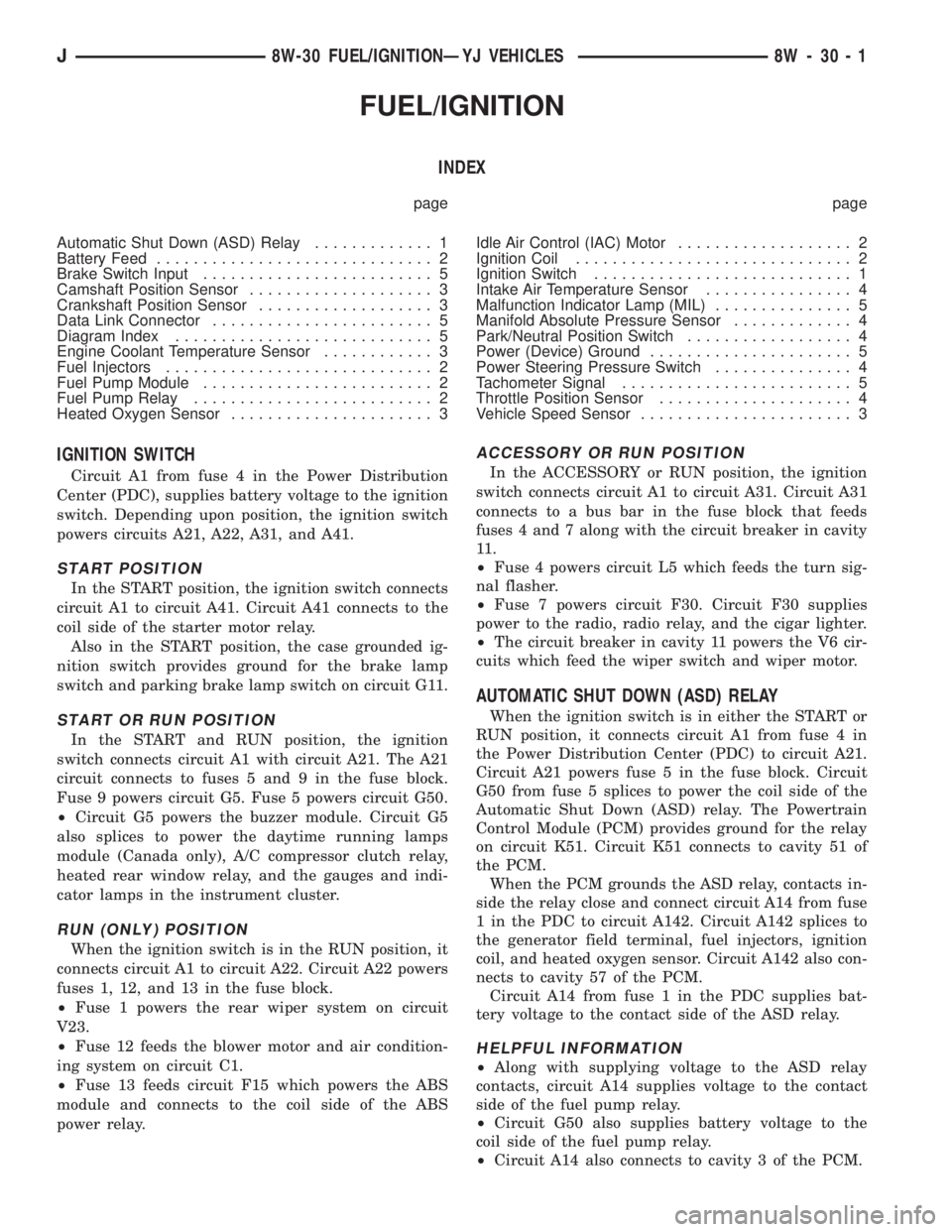
FUEL/IGNITION
INDEX
page page
Automatic Shut Down (ASD) Relay............. 1
Battery Feed.............................. 2
Brake Switch Input......................... 5
Camshaft Position Sensor.................... 3
Crankshaft Position Sensor................... 3
Data Link Connector........................ 5
Diagram Index............................ 5
Engine Coolant Temperature Sensor............ 3
Fuel Injectors............................. 2
Fuel Pump Module......................... 2
Fuel Pump Relay.......................... 2
Heated Oxygen Sensor...................... 3Idle Air Control (IAC) Motor................... 2
Ignition Coil.............................. 2
Ignition Switch............................ 1
Intake Air Temperature Sensor................ 4
Malfunction Indicator Lamp (MIL)............... 5
Manifold Absolute Pressure Sensor............. 4
Park/Neutral Position Switch.................. 4
Power (Device) Ground...................... 5
Power Steering Pressure Switch............... 4
Tachometer Signal......................... 5
Throttle Position Sensor..................... 4
Vehicle Speed Sensor....................... 3
IGNITION SWITCH
Circuit A1 from fuse 4 in the Power Distribution
Center (PDC), supplies battery voltage to the ignition
switch. Depending upon position, the ignition switch
powers circuits A21, A22, A31, and A41.
START POSITION
In the START position, the ignition switch connects
circuit A1 to circuit A41. Circuit A41 connects to the
coil side of the starter motor relay.
Also in the START position, the case grounded ig-
nition switch provides ground for the brake lamp
switch and parking brake lamp switch on circuit G11.
START OR RUN POSITION
In the START and RUN position, the ignition
switch connects circuit A1 with circuit A21. The A21
circuit connects to fuses 5 and 9 in the fuse block.
Fuse 9 powers circuit G5. Fuse 5 powers circuit G50.
²Circuit G5 powers the buzzer module. Circuit G5
also splices to power the daytime running lamps
module (Canada only), A/C compressor clutch relay,
heated rear window relay, and the gauges and indi-
cator lamps in the instrument cluster.
RUN (ONLY) POSITION
When the ignition switch is in the RUN position, it
connects circuit A1 to circuit A22. Circuit A22 powers
fuses 1, 12, and 13 in the fuse block.
²Fuse 1 powers the rear wiper system on circuit
V23.
²Fuse 12 feeds the blower motor and air condition-
ing system on circuit C1.
²Fuse 13 feeds circuit F15 which powers the ABS
module and connects to the coil side of the ABS
power relay.
ACCESSORY OR RUN POSITION
In the ACCESSORY or RUN position, the ignition
switch connects circuit A1 to circuit A31. Circuit A31
connects to a bus bar in the fuse block that feeds
fuses 4 and 7 along with the circuit breaker in cavity
11 .
²Fuse 4 powers circuit L5 which feeds the turn sig-
nal flasher.
²Fuse 7 powers circuit F30. Circuit F30 supplies
power to the radio, radio relay, and the cigar lighter.
²The circuit breaker in cavity 11 powers the V6 cir-
cuits which feed the wiper switch and wiper motor.
AUTOMATIC SHUT DOWN (ASD) RELAY
When the ignition switch is in either the START or
RUN position, it connects circuit A1 from fuse 4 in
the Power Distribution Center (PDC) to circuit A21.
Circuit A21 powers fuse 5 in the fuse block. Circuit
G50 from fuse 5 splices to power the coil side of the
Automatic Shut Down (ASD) relay. The Powertrain
Control Module (PCM) provides ground for the relay
on circuit K51. Circuit K51 connects to cavity 51 of
the PCM.
When the PCM grounds the ASD relay, contacts in-
side the relay close and connect circuit A14 from fuse
1 in the PDC to circuit A142. Circuit A142 splices to
the generator field terminal, fuel injectors, ignition
coil, and heated oxygen sensor. Circuit A142 also con-
nects to cavity 57 of the PCM.
Circuit A14 from fuse 1 in the PDC supplies bat-
tery voltage to the contact side of the ASD relay.
HELPFUL INFORMATION
²Along with supplying voltage to the ASD relay
contacts, circuit A14 supplies voltage to the contact
side of the fuel pump relay.
²Circuit G50 also supplies battery voltage to the
coil side of the fuel pump relay.
²Circuit A14 also connects to cavity 3 of the PCM.
J8W-30 FUEL/IGNITIONÐYJ VEHICLES 8W - 30 - 1
Page 2028 of 2198
²Circuit K60 connects to cavity 60 of the PCM.
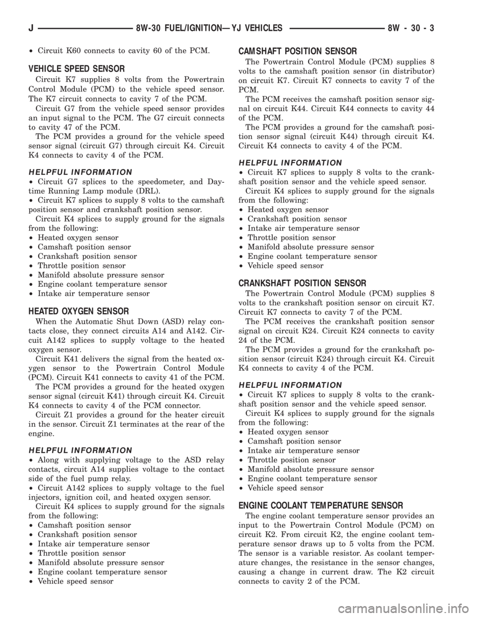
VEHICLE SPEED SENSOR
Circuit K7 supplies 8 volts from the Powertrain
Control Module (PCM) to the vehicle speed sensor.
The K7 circuit connects to cavity 7 of the PCM.
Circuit G7 from the vehicle speed sensor provides
an input signal to the PCM. The G7 circuit connects
to cavity 47 of the PCM.
The PCM provides a ground for the vehicle speed
sensor signal (circuit G7) through circuit K4. Circuit
K4 connects to cavity 4 of the PCM.
HELPFUL INFORMATION
²Circuit G7 splices to the speedometer, and Day-
time Running Lamp module (DRL).
²Circuit K7 splices to supply 8 volts to the camshaft
position sensor and crankshaft position sensor.
Circuit K4 splices to supply ground for the signals
from the following:
²Heated oxygen sensor
²Camshaft position sensor
²Crankshaft position sensor
²Throttle position sensor
²Manifold absolute pressure sensor
²Engine coolant temperature sensor
²Intake air temperature sensor
HEATED OXYGEN SENSOR
When the Automatic Shut Down (ASD) relay con-
tacts close, they connect circuits A14 and A142. Cir-
cuit A142 splices to supply voltage to the heated
oxygen sensor.
Circuit K41 delivers the signal from the heated ox-
ygen sensor to the Powertrain Control Module
(PCM). Circuit K41 connects to cavity 41 of the PCM.
The PCM provides a ground for the heated oxygen
sensor signal (circuit K41) through circuit K4. Circuit
K4 connects to cavity 4 of the PCM connector.
Circuit Z1 provides a ground for the heater circuit
in the sensor. Circuit Z1 terminates at the rear of the
engine.
HELPFUL INFORMATION
²Along with supplying voltage to the ASD relay
contacts, circuit A14 supplies voltage to the contact
side of the fuel pump relay.
²Circuit A142 splices to supply voltage to the fuel
injectors, ignition coil, and heated oxygen sensor.
Circuit K4 splices to supply ground for the signals
from the following:
²Camshaft position sensor
²Crankshaft position sensor
²Intake air temperature sensor
²Throttle position sensor
²Manifold absolute pressure sensor
²Engine coolant temperature sensor
²Vehicle speed sensor
CAMSHAFT POSITION SENSOR
The Powertrain Control Module (PCM) supplies 8
volts to the camshaft position sensor (in distributor)
on circuit K7. Circuit K7 connects to cavity 7 of the
PCM.
The PCM receives the camshaft position sensor sig-
nal on circuit K44. Circuit K44 connects to cavity 44
of the PCM.
The PCM provides a ground for the camshaft posi-
tion sensor signal (circuit K44) through circuit K4.
Circuit K4 connects to cavity 4 of the PCM.
HELPFUL INFORMATION
²Circuit K7 splices to supply 8 volts to the crank-
shaft position sensor and the vehicle speed sensor.
Circuit K4 splices to supply ground for the signals
from the following:
²Heated oxygen sensor
²Crankshaft position sensor
²Intake air temperature sensor
²Throttle position sensor
²Manifold absolute pressure sensor
²Engine coolant temperature sensor
²Vehicle speed sensor
CRANKSHAFT POSITION SENSOR
The Powertrain Control Module (PCM) supplies 8
volts to the crankshaft position sensor on circuit K7.
Circuit K7 connects to cavity 7 of the PCM.
The PCM receives the crankshaft position sensor
signal on circuit K24. Circuit K24 connects to cavity
24 of the PCM.
The PCM provides a ground for the crankshaft po-
sition sensor (circuit K24) through circuit K4. Circuit
K4 connects to cavity 4 of the PCM.
HELPFUL INFORMATION
²Circuit K7 splices to supply 8 volts to the crank-
shaft position sensor and the vehicle speed sensor.
Circuit K4 splices to supply ground for the signals
from the following:
²Heated oxygen sensor
²Camshaft position sensor
²Intake air temperature sensor
²Throttle position sensor
²Manifold absolute pressure sensor
²Engine coolant temperature sensor
²Vehicle speed sensor
ENGINE COOLANT TEMPERATURE SENSOR
The engine coolant temperature sensor provides an
input to the Powertrain Control Module (PCM) on
circuit K2. From circuit K2, the engine coolant tem-
perature sensor draws up to 5 volts from the PCM.
The sensor is a variable resistor. As coolant temper-
ature changes, the resistance in the sensor changes,
causing a change in current draw. The K2 circuit
connects to cavity 2 of the PCM.
J8W-30 FUEL/IGNITIONÐYJ VEHICLES 8W - 30 - 3
Page 2029 of 2198
The PCM provides a ground for the engine coolant
temperature sensor signal (circuit K2) through circuit
K4. Circuit K4 connects to cavity 4 of the PCM con-
nector.
HELPFUL INFORMATION
Circuit K4 splices to supply ground for the signals
from the following:
²Heated oxygen sensor
²Camshaft position sensor
²Crankshaft position sensor
²Intake air temperature sensor
²Throttle position sensor
²Manifold absolute pressure sensor
²Vehicle speed sensor
THROTTLE POSITION SENSOR
From the Powertrain Control Module (PCM), cir-
cuit K6 supplies 5 volts to the Throttle Position Sen-
sor (TPS). Circuit K6 connects to cavity 6 of the
PCM.
Circuit K22 delivers the TPS signal to the PCM.
Circuit K22 connects to cavity 22 of the PCM.
The PCM provides a ground for the throttle posi-
tion sensor signal (circuit K22) through circuit K4.
Circuit K4 connects to cavity 4 of the PCM.
HELPFUL INFORMATION
Refer to Group 14 for throttle position sensor oper-
ation.
Circuit K6 splices to supply 5 volts to the Manifold
Absolute Pressure (MAP) sensor.
Circuit K4 splices to supply ground for the signals
from the following:
²Heated oxygen sensor
²Camshaft position sensor
²Crankshaft position sensor
²Intake air temperature sensor
²Manifold absolute pressure sensor
²Engine coolant temperature sensor
²Vehicle speed sensor
MANIFOLD ABSOLUTE PRESSURE (MAP) SENSOR
From the Powertrain Control Module (PCM), cir-
cuit K6 supplies 5 volts to the Manifold Absolute
Pressure (MAP) sensor. Circuit K6 connects to cavity
6 of the PCM.
Circuit K1 delivers the MAP signal to the PCM.
Circuit K1 connects to cavity 1 of the PCM.
The PCM provides a ground for the MAP sensor
signal (circuit K1) through circuit K4. Circuit K4 con-
nects to cavity 4 of the PCM.
HELPFUL INFORMATION
Refer to Group 14 for MAP sensor operation.
Circuit K6 splices to supply 5 volts to the throttle
position sensor.Circuit K4 splices to supply ground for the signals
from the following:
²Heated oxygen sensor
²Camshaft position sensor
²Crankshaft position sensor
²Intake air temperature sensor
²Throttle position sensor
²Engine coolant temperature sensor
²Vehicle speed sensor
INTAKE AIR TEMPERATURE SENSOR
The intake air temperature sensor provides an in-
put to the Powertrain Control Module (PCM) on cir-
cuit K21. Circuit K21 connects to cavity 21 of the
PCM.
From circuit K21, the intake air temperature sen-
sor draws voltage from the PCM. The sensor is a
variable resistor. As intake air temperature changes,
the resistance in the sensor changes, causing a
change in current draw.
The PCM provides a ground for the intake air tem-
perature sensor signal (circuit K21) through circuit
K4. Circuit K4 connects to cavity 4 of the PCM.
HELPFUL INFORMATION
Circuit K4 splices to supply ground for the signals
from the following:
²Heated oxygen sensor
²Camshaft position sensor
²Crankshaft position sensor
²Throttle position sensor
²Manifold absolute pressure sensor
²Engine coolant temperature sensor
²Vehicle speed sensor
PARK/NEUTRAL POSITION SWITCH
When closed, the case-grounded park/neutral posi-
tion switch provides a ground path on circuit T41 for
the coil side of the starter motor relay. Circuit A41
from the ignition switch provides battery voltage to
the coil side of the relay.
Circuit T41 splices to cavity 30 of the Powertrain
Control Module (PCM). The park/neutral position
switch provides an input to the (PCM).
HELPFUL INFORMATION
²In the START position, the ignition switch con-
nects circuit A1 from the Power Distribution Center
(PDC) to circuit A41. Fuse 4 in the fuse block pro-
tects circuits A1 and A41.
²The Park/Neutral position switch and back-up
lamp switch are molded together.
POWER STEERING PRESSURE SWITCH
The Powertrain Control Module (PCM) supplies
voltage to the power steering pressure switch on cir-
cuit K10. Circuit Z1 provides ground for the switch.
When the switch closes, voltage flows through the
8W - 30 - 4 8W-30 FUEL/IGNITIONÐYJ VEHICLESJ
Page 2030 of 2198
switch to ground on circuit Z1. The switch closes dur-
ing periods of high power steering pump load and
low engine speed; such as parking maneuvers. Cir-
cuit K10 connects to cavity 10 of the PCM.
TACHOMETER SIGNAL
The Powertrain Control Module (PCM) supplies the
signal for the tachometer on circuit G21. Circuit G21
connects to cavity 43 of the PCM.
MALFUNCTION INDICATOR LAMP (MIL)
The Powertrain Control Module (PCM) provides
ground for the instrument cluster malfunction indica-
tor lamp on circuit G3. The MIL displays the mes-
sage CHECK ENGINE when illuminated. Circuit G5
provides voltage for the lamp.
DATA LINK CONNECTOR
Circuit G50 supplies battery voltage to the data
link connector. Circuit G50 originates at fuse 5 in the
fuse block. Circuit G50 is double crimped at the data
link connector and connects to cavity 9 of the Power-
train Control Module (PCM).
Circuit A21 from the ignition switch powers fuse 5
when the switch is in the START or RUN positions.
In the START or RUN position the ignition switch
connects circuit A1 from fuse 4 in the Power Distri-
bution Center (PDC) with circuit A21.
Circuit D20 connects to cavity 45 of the PCM. Cir-
cuit D20 is the SCI receive circuit for the PCM.
Circuit D21 connects to cavity 25 of the PCM. Cir-
cuit D21 is the SCI transmit circuit for the PCM.
Circuit Z11 provides ground for the data link con-
nector. Circuit Z11 splices to circuit Z1 which termi-
nates at the right rear of the engine. Circuit Z11 also
connects to cavity 5 of the PCM.
HELPFUL INFORMATION
²Circuit Z1 also supplies a ground for the PCM
high current drivers.
²If the system loses ground for the Z1 and Z11 cir-
cuits at the right rear of the engine, the vehicle will
not operate. Check the connection at the ganged-
ground circuit eyelet.
BRAKE SWITCH INPUT
Circuit V40 provides the brake switch input to the
Powertrain Control Module (PCM). Circuit V40 con-
nects to cavity 29 of the PCM.
POWER (DEVICE) GROUND
Circuit Z11 connects to cavities 11 and 12 of the
Powertrain Control Module (PCM). The Z1 circuit
provides ground for PCM internal drivers that oper-
ate high current devices like the injectors and igni-
tion coil.
Internal to the PCM, the power (device) ground cir-
cuit connects to the PCM sensor return circuit (from
circuit K4).
HELPFUL INFORMATION
²The grounding point for circuit Z1 is the right rear
of the engine.
²If the system loses ground for the Z1 circuits at
the rear of the engine, the vehicle will not operate.
Check the connection at the ganged-ground circuit
eyelet.
DIAGRAM INDEX
Component Page
Automatic Shut Down Relay...............8W-30-6, 14
Camshaft Position Sensor................8W-30-10, 16
Crankshaft Position Sensor...............8W-30-10, 16
Data Link Connector...................8W-30-11, 17
Daytime Running Lamps (DRL) Module.......8W-30-11, 17
Engine Coolant Temperature Sensor..........8W-30-9, 18
Fuel Pump Relay........................8W-30-20
Fuel Tank Level Unit......................8W-30-21
Fuse 1 (PDC)........................8W-30-6, 14
Fuse 4 (PDC)........................8W-30-6, 14
Fuse 5 (Fuse Block).................8W-30-6, 14, 20
Heated Oxygen Sensor..................8W-30-7, 15
Idle Air Control Motor..................8W-30-12, 18
Ignition Switch.....................8W-30-6, 14, 20
Ignition Coil........................8W-30-12, 18
Injectors (4.0L).........................8W-30-13
Injectors (2.5L)..........................8W-30-8
Instrument Cluster....................8W-30-11, 17
Intake Air Temperature Sensor.............8W-30-9, 18
MAP Sensor.........................8W-30-9, 18
Power Steering Pressure Switch..............8W-30-12
Powertrain Control Module.............8W-30-6 thru 21
Throttle Position Sensor.................8W-30-9, 18
Vehicle Speed Sensor..................8W-30-11, 17
J8W-30 FUEL/IGNITIONÐYJ VEHICLES 8W - 30 - 5
Page 2058 of 2198
INSTRUMENT CLUSTER
INSTRUMENT CLUSTER
The instrument cluster contains the gauges and
warning lamps. All gauges have magnetic move-
ments.
When the ignition switch is in either the START or
RUN position, circuit A1 from fuse 4 in the Power
Distribution Center (PDC) connects to circuit A21.
Circuit A21 powers fuse 9 in the fuse block. Fuse 9
powers circuit G5. One branch of circuit G5 connects
directly to the combination buzzer. The other branch
of circuit G5 splices to power the gauges, speedome-
ter, tachometer, voltmeter, indicator lamps, and
warning lamps in the instrument cluster.
When the parking lamps or headlamps are ON, the
headlamp switch connects circuit F33 to circuit L7.
Circuit L7 splices to the dimmer switch. Circuit E1
from the dimmer switch powers fuse 10 in the fuse
block when the parking lamps or headlamps are ON.
Circuit E2 from fuse 10 in the fuse block feeds the
illumination lamps in the instrument cluster.
Circuit Z1 provides ground the instrument cluster
illumination lamps, gauges and warning lamps.
HELPFUL INFORMATION
²Circuit G5 also powers the heated rear window,
A/C compressor clutch relay. On Canadian vehicles,
circuit G5 powers the Daytime Running Lamps
(DRL) module.
²Circuit F33 originates at fuse 8 in the fuse block.
Circuit A6 from fuse 3 in the PDC powers fuse 8 in
the fuse block.
ENGINE COOLANT TEMPERATURE GAUGE
Circuit G20 connects the engine coolant tempera-
ture gauge to the engine coolant temperature sensor.
The sensor is a variable resistor and case grounded
to the engine. Circuit G5 connects to the instrument
cluster and supplies voltage for the gauge.
The gauge uses two coils. The first coil has fixed
current flowing through it to maintain magnetic field
strength. Circuit Z1 provides ground for the fixed
current coil. The current level passing through the
second coil is controlled by the variable resistor in
the engine coolant temperature sender. The changing
current varies the magnetic field in the second coil.
Refer to group 8E, Instrument Panel and Gauges
for gauge operation.
FUEL GAUGE
Circuit G4 connects the fuel level sensor to the fuel
gauge in the instrument cluster. Circuit G5 supplies
voltage to the fuel gauge. The fuel level sensor draws
voltage from circuit G5 through the fuel gauge on cir-
cuit G4.The gauge uses two coils. The first coil has fixed
current flowing through it to maintain magnetic field
strength. Circuit Z1 provides ground for the fixed
current coil. The current level passing through the
second coil is controlled by the variable resistor in
the fuel level sensor. The changing current varies the
magnetic field in the second coil.
Circuit Z2 provides the ground path for the fuel
level sensor.
Refer to group 8E, Instrument Panel and Gauges
for gauge operation.
OIL PRESSURE GAUGE
The case grounded oil pressure sending unit is a
variable resistor. The sending unit connects to the oil
pressure gauge on circuit G60.
Circuit G5 connects to the instrument cluster and
supplies battery voltage to the oil pressure gauge.
The gauge uses two coils. The first coil has fixed cur-
rent flowing through it to maintain magnetic field
strength. Circuit Z1 provides ground for the fixed
current coil. The current level passing through the
second coil is controlled by the variable resistor in
the oil pressure sending unit. The changing current
varies the magnetic field in the second coil.
Refer to group 8E, Instrument Panel and Gauges
for gauge operation.
TACHOMETER
The Powertrain Control Module (PCM) provides
the tachometer signal to the electronic tachometer on
circuit G21. Circuit G21 originates at cavity 43 of the
PCM. Circuit Z1 provides ground for the tachometer's
internal logic circuits.
SPEEDOMETER
The electronic speedometer and odometer receive a
signal from the vehicle speed sensor on circuit G7.
Circuit G5 connects to the instrument cluster and
supplies battery voltage to the speedometer. Circuit
Z1 provides ground for the speedometer internal logic
circuits.
Circuit G7 splices to connect to the Powertrain
Control Module (PCM) and if equipped, the Daytime
Running Lamps (DRL) module.
FOUR-WHEEL DRIVE (4WD) INDICATOR LAMP
When the 4WD switch closes, circuit Z1 provides
ground for the 4WD indicator lamp in the instrument
panel. Circuit G5 connects to the instrument cluster
and supplies battery voltage to the 4WD indicator
lamp. Circuit G1 connects the indicator lamp to the
4WD switch.
J8W-40 INSTRUMENT CLUSTERÐYJ VEHICLES 8W - 40 - 1
Page 2059 of 2198
MALFUNCTION INDICATOR (CHECK ENGINE)
LAMP
The Powertrain Control Module (PCM) provides
ground for the malfunction indicator (Check Engine)
lamp on circuit G3. Circuit G3 connects to cavity 32
of the PCM. Circuit G5 connects to the instrument
cluster and supplies battery voltage for the malfunc-
tion indicator lamp. When illuminated, the malfunc-
tion indicator lamp displays the message CHECK
ENGINE.
For information regarding diagnostic trouble code
access using the malfunction indicator lamp, refer to
Group 14, Fuel Systems.
UP-SHIFT LAMP
On vehicles equipped with a manual transmission,
the Powertrain Control Module (PCM) provides
ground for the Up-Shift lamp on circuit K54. Circuit
G5 provides battery voltage for the lamp.
ABS WARNING LAMP
Circuit G5 provides power for the ABS warning
lamp at the instrument cluster. Ground for the ABS
warning lamp is provided by either the ABS control
module or by the ABS power relay when the relay is
not energized. The ABS control module illuminates
the lamp by providing ground on circuit G19.
Circuit G19 splices to connect to circuit B15
through a diode. When the ABS power relay is not
energized, it connects circuit B15 to circuit Z12. The
ground path for the warning lamp is provided
through the diode to circuit B15, through the ABS
power relay to ground on circuit Z12.
The diode between circuit G19 and B15 prevents
voltage from flowing to the ABS control module when
the ABS power relay switches to supply power on cir-
cuit B15.
BRAKE WARNING LAMP
Circuit G5 provides battery voltage for the brake
warning lamp. Circuit G11 can provide ground for
the lamp in 3 ways. The first ground path is through
the ignition switch when the key is in the START po-
sition.
The second ground path for the brake warning
lamp on circuit G11 is through the case grounded
brake warning switch. When the switch closes it pro-
vides a ground.
The third ground path on circuit G11 is through
the case grounded park brake switch. When the
switch closes it provides ground.
HIGH BEAM INDICATOR LAMP
Circuit G34 supplies power for the high-beam indi-
cator lamp when the operator either flashes the opti-
cal horn (high beams) or selects high beam operation.
Circuit Z1 provides the ground path for the lamp.
Circuit L3 from the headlamp switch powers the
high beam circuits of the headlamps. On vehicles not
equipped with Daytime Running Lamps (DRL), cir-
cuit G34 double crimps to circuit L3 at the bulkhead
connector.
On vehicles equipped with DRL, circuit L3 splices
to the DRL module. The DRL module powers circuit
G34.
TURN SIGNAL INDICATOR LAMPS
Circuit L61 supplies battery voltage to the left turn
signal indicator lamp. The right turn signal indicator
lamp receives battery voltage from circuit L60. The
turn signal/hazard flasher switch powers circuits L60
and L61. Circuit Z1 provides ground for the lamps.
HELPFUL INFORMATION
²If the warning lamps, gauges and indicator lamps
don't operate, check fuse 4 in the PDC and fuse 9 in
the fuse block.
²If the illumination lamps don't operate, check fuse
10 in the fuse block.
DIAGRAM INDEX
Component Page
4WD Switch............................8W-40-9
ABS Control Module......................8W-40-5
Brake Warning Switch.....................8W-40-5
Combination Buzzer.....................8W-40-7, 8
Daytime Running Lamp (DRL) Module.........8W-40-4, 6
Engine Coolant Temperature Sensor...........8W-40-7, 8
Engine Oil Pressure Sensor..................8W-40-9
Fuse 3 (PDC).......................8W-40-3, 7, 8
Fuse 4 (PDC).......................8W-40-4, 7, 8
Fuse 7 (PDC)...........................8W-40-6
Fuse 8 (Fuse Block)...................8W-40-3, 7, 8
Fuse 9 (Fuse Block).......................8W-40-8
Fuse 10 (Fuse Block).................8W-40-3, 7, 10
Gauge Package......................8W-40-7, 8, 9
Headlamp Switch...................8W-40-3, 6, 7, 8
Headlamp Dimmer Switch...................8W-40-6
Ignition Switch......................8W-40-4, 5, 8
Instrument Cluster...................8W-40-3 thru 9
Panel Lamp Dimmer Switch..............8W-40-3, 7, 8
Park Brake Switch........................8W-40-5
Powertrain Control Module.................8W-40-4, 5
8W - 40 - 2 8W-40 INSTRUMENT CLUSTERÐYJ VEHICLESJ