1995 JEEP CHEROKEE Maintenance
[x] Cancel search: MaintenancePage 149 of 2198
connect scan tool and proceed to next step.
(7)Repeatconventional bleed procedure described
in steps (4) and (5).
(8) Top off master cylinder fluid level and verify
proper brake operation before moving vehicle.
BRAKELINES AND HOSES
Metal brakelines and rubber brake hoses should be
inspected periodically and replaced if damaged.
Rubber brake hoses should be replaced if cut,
cracked, swollen, or leaking. Rubber hoses must be
replaced as they are not repairable.
Steel brakelines should be inspected any time the
vehicle is in for normal maintenance. This is impor-
tant on high mileage vehicles. It is especially impor-
tant when the vehicle is operated on roads that are
salted during winter months.
Heavily rusted/corroded brake rotors, drums,
support plates, and brakelines should be
cleaned and carefully inspected. Heavy rust
buildup can hide severe damage to a compo-
nent. Severely rusted parts should be replaced
if condition is suspect.
BRAKELINE CHARTS
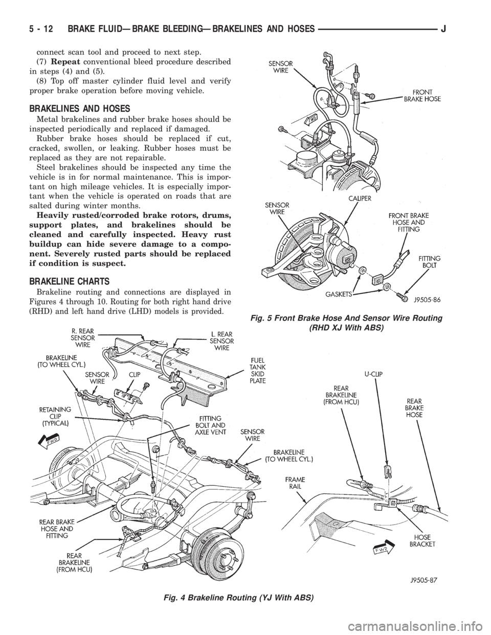
Brakeline routing and connections are displayed in
Figures 4 through 10. Routing for both right hand drive
(RHD) and left hand drive (LHD) models is provided.
Fig. 4 Brakeline Routing (YJ With ABS)
Fig. 5 Front Brake Hose And Sensor Wire Routing
(RHD XJ With ABS)
5 - 12 BRAKE FLUIDÐBRAKE BLEEDINGÐBRAKELINES AND HOSESJ
Page 276 of 2198
WARNING: DO NOT USE OPEN FLAME AS A
SOURCE OF ADDITIONAL LIGHT FOR VIEWING
TEST INDICATOR. EXPLOSIVE HYDROGEN GAS
MAY BE PRESENT IN THE AREA SURROUNDING
BATTERY.
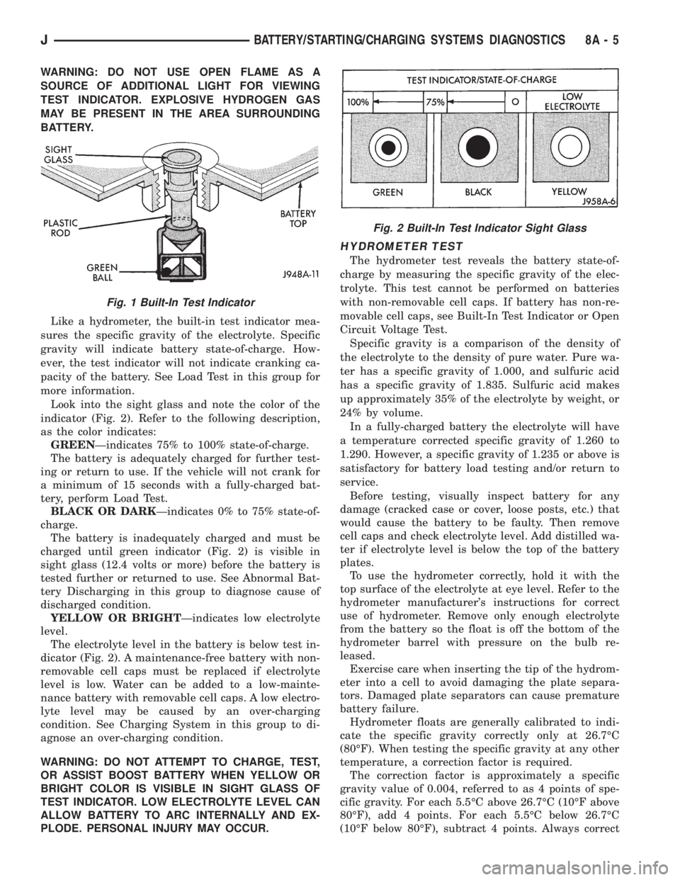
Like a hydrometer, the built-in test indicator mea-
sures the specific gravity of the electrolyte. Specific
gravity will indicate battery state-of-charge. How-
ever, the test indicator will not indicate cranking ca-
pacity of the battery. See Load Test in this group for
more information.
Look into the sight glass and note the color of the
indicator (Fig. 2). Refer to the following description,
as the color indicates:
GREENÐindicates 75% to 100% state-of-charge.
The battery is adequately charged for further test-
ing or return to use. If the vehicle will not crank for
a minimum of 15 seconds with a fully-charged bat-
tery, perform Load Test.
BLACK OR DARKÐindicates 0% to 75% state-of-
charge.
The battery is inadequately charged and must be
charged until green indicator (Fig. 2) is visible in
sight glass (12.4 volts or more) before the battery is
tested further or returned to use. See Abnormal Bat-
tery Discharging in this group to diagnose cause of
discharged condition.
YELLOW OR BRIGHTÐindicates low electrolyte
level.
The electrolyte level in the battery is below test in-
dicator (Fig. 2). A maintenance-free battery with non-
removable cell caps must be replaced if electrolyte
level is low. Water can be added to a low-mainte-
nance battery with removable cell caps. A low electro-
lyte level may be caused by an over-charging
condition. See Charging System in this group to di-
agnose an over-charging condition.
WARNING: DO NOT ATTEMPT TO CHARGE, TEST,
OR ASSIST BOOST BATTERY WHEN YELLOW OR
BRIGHT COLOR IS VISIBLE IN SIGHT GLASS OF
TEST INDICATOR. LOW ELECTROLYTE LEVEL CAN
ALLOW BATTERY TO ARC INTERNALLY AND EX-
PLODE. PERSONAL INJURY MAY OCCUR.
HYDROMETER TEST
The hydrometer test reveals the battery state-of-
charge by measuring the specific gravity of the elec-
trolyte. This test cannot be performed on batteries
with non-removable cell caps. If battery has non-re-
movable cell caps, see Built-In Test Indicator or Open
Circuit Voltage Test.
Specific gravity is a comparison of the density of
the electrolyte to the density of pure water. Pure wa-
ter has a specific gravity of 1.000, and sulfuric acid
has a specific gravity of 1.835. Sulfuric acid makes
up approximately 35% of the electrolyte by weight, or
24% by volume.
In a fully-charged battery the electrolyte will have
a temperature corrected specific gravity of 1.260 to
1.290. However, a specific gravity of 1.235 or above is
satisfactory for battery load testing and/or return to
service.
Before testing, visually inspect battery for any
damage (cracked case or cover, loose posts, etc.) that
would cause the battery to be faulty. Then remove
cell caps and check electrolyte level. Add distilled wa-
ter if electrolyte level is below the top of the battery
plates.
To use the hydrometer correctly, hold it with the
top surface of the electrolyte at eye level. Refer to the
hydrometer manufacturer's instructions for correct
use of hydrometer. Remove only enough electrolyte
from the battery so the float is off the bottom of the
hydrometer barrel with pressure on the bulb re-
leased.
Exercise care when inserting the tip of the hydrom-
eter into a cell to avoid damaging the plate separa-
tors. Damaged plate separators can cause premature
battery failure.
Hydrometer floats are generally calibrated to indi-
cate the specific gravity correctly only at 26.7ÉC
(80ÉF). When testing the specific gravity at any other
temperature, a correction factor is required.
The correction factor is approximately a specific
gravity value of 0.004, referred to as 4 points of spe-
cific gravity. For each 5.5ÉC above 26.7ÉC (10ÉF above
80ÉF), add 4 points. For each 5.5ÉC below 26.7ÉC
(10ÉF below 80ÉF), subtract 4 points. Always correct
Fig. 1 Built-In Test Indicator
Fig. 2 Built-In Test Indicator Sight Glass
JBATTERY/STARTING/CHARGING SYSTEMS DIAGNOSTICS 8A - 5
Page 277 of 2198

the specific gravity for temperature variation. Test
the specific gravity of the electrolyte in each battery
cell.
Example: A battery is tested at -12.2ÉC (10ÉF) and
has a specific gravity of 1.240. Determine the actual
specific gravity as follows:
(1) Determine the number of degrees above or be-
low 26.7ÉC (80ÉF):
26.6ÉC - -12.2ÉC = 38.8ÉC (80ÉF - 10ÉF = 70ÉF)
(2) Divide the result from step 1 by 5.5 (10):
38.8ÉC/5.5 = 7 (70ÉF/10 = 7)
(3) Multiply the result from step 2 by the temper-
ature correction factor (0.004):
7 x 0.004 = 0.028
(4) The temperature at testing was below 26.7ÉC
(80ÉF); therefore, the temperature correction is sub-
tracted:
1.240 - 0.028 = 1.212
The corrected specific gravity of the battery in this
example is 1.212.
If the specific gravity of all cells is above 1.235, but
variation between cells is more than 50 points
(0.050), the battery should be replaced.
If the specific gravity of one or more cells is less
than 1.235, charge the battery at a rate of approxi-
mately 5 amperes. Continue charging until 3 consec-
utive specific gravity tests, taken at 1-hour intervals,
are constant. If the cell specific gravity variation is
more than 50 points (0.050) at the end of the charge
period, replace the battery.
When the specific gravity of all cells is above 1.235,
and cell variation is less than 50 points (0.050), the
battery may be load tested.
OPEN CIRCUIT VOLTAGE TEST
A battery open circuit voltage (no load) test will
show state-of-charge of a battery. This test can be
used in place of the hydrometer test if a hydrometer
is not available, or for maintenance-free batteries
with non-removable cell caps.
Before proceeding with this test or load test,
completely charge battery as described in Bat-
tery Charging in this group.
Test battery open circuit voltage as follows:
(1) Before measuring open circuit voltage the sur-
face charge must be removed from the battery. Turn
headlamps on for 15 seconds, then allow up to 5 min-
utes for voltage to stabilize.
(2) Remove both battery cables, negative first.
(3) Using a voltmeter connected to the battery
posts (refer to instructions provided with voltmeter)
measure open circuit voltage (Fig. 3).
See Open Circuit Voltage chart. This voltage read-
ing will indicate state-of-charge, but will not reveal
cranking capacity. If a battery has an open circuit
voltage reading of 12.4 volts or greater, it may be
load tested. A battery that will not endure a load test
is faulty and must be replaced.
LOAD TEST
A battery load test will verify battery cranking ca-
pacity. The test is based on the Cold Cranking Am-
perage (CCA) rating of the battery. See Battery
Classifications and Ratings chart in Specifications, at
the back of this group.
WARNING: IF BATTERY SHOWS SIGNS OF FREEZ-
ING, LEAKING, LOOSE POSTS, OR LOW ELECTRO-
LYTE LEVEL, DO NOT LOAD TEST. PERSONAL
INJURY AND/OR VEHICLE DAMAGE MAY RESULT.
Before performing load test, the battery must
be FULLY-CHARGED.
(1) Remove both battery cables, negative first. Bat-
tery top and posts should be clean.
(2) Connect a suitable volt-ammeter-load tester
(Fig. 4) to the battery posts (Fig. 5). Refer to operat-
ing instructions provided with the tester being used.
Check the open circuit voltage (no load) of the bat-
tery. Open circuit voltage must be 12.4 volts or
greater.
(3) Rotate the load control knob (carbon pile rheo-
stat) to apply a 300 amp load for 15 seconds, then re-
turn the control knob to OFF (Fig. 6). This will
remove the surface charge from the battery.
(4) Allow the battery to stabilize to open circuit
voltage. It may take up to 5 minutes for voltage to
stabilize.
OPEN CIRCUIT VOLTAGE
Fig. 3 Testing Open Circuit Voltage
8A - 6 BATTERY/STARTING/CHARGING SYSTEMS DIAGNOSTICSJ
Page 296 of 2198
BATTERY/STARTER/GENERATOR SERVICE
CONTENTS
page page
BATTERY............................... 1
GENERATOR............................ 6SPECIFICATIONS......................... 8
STARTER AND STARTER RELAY............. 4
GENERAL INFORMATION
Group 8B covers battery, starter and generator ser-
vice procedures. For diagnosis of these components
and their related systems, refer to Group 8A - Bat-tery/Starting/Charging Systems Diagnostics. Refer to
Group 8W - Wiring Diagrams for complete circuit de-
scriptions and diagrams.
BATTERY
GENERAL INFORMATION
This section covers battery service procedures only.
For battery maintenance procedures, refer to Group 0
- Lubrication and Maintenance. While battery charg-
ing can be considered a service or maintenance pro-
cedure, this information is located in Group 8A -
Battery/Starting/Charging Systems Diagnostics. This
was done because the battery must be fully charged
before any diagnosis is performed.
It is important that the battery, starting, and
charging systems be thoroughly tested and inspected
any time a battery needs to be charged or replaced.
The cause of abnormal discharge, over-charging, or
premature failure of the battery must be diagnosed
and corrected before a battery is replaced or returned
to service. Refer to Group 8A - Battery/Starting/
Charging Systems Diagnostics.
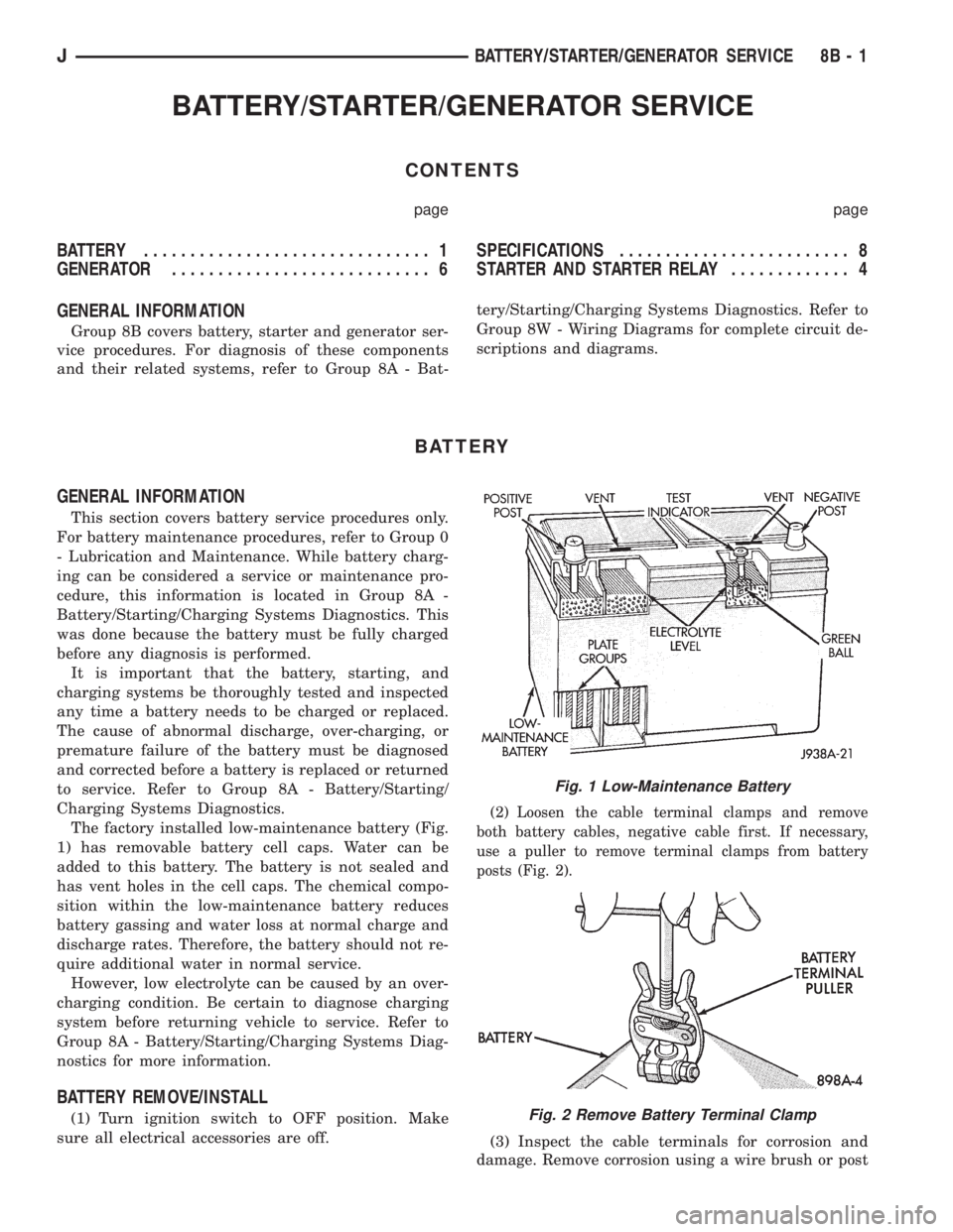
The factory installed low-maintenance battery (Fig.
1) has removable battery cell caps. Water can be
added to this battery. The battery is not sealed and
has vent holes in the cell caps. The chemical compo-
sition within the low-maintenance battery reduces
battery gassing and water loss at normal charge and
discharge rates. Therefore, the battery should not re-
quire additional water in normal service.
However, low electrolyte can be caused by an over-
charging condition. Be certain to diagnose charging
system before returning vehicle to service. Refer to
Group 8A - Battery/Starting/Charging Systems Diag-
nostics for more information.
BATTERY REMOVE/INSTALL
(1) Turn ignition switch to OFF position. Make
sure all electrical accessories are off.
(2) Loosen the cable terminal clamps and remove
both battery cables, negative cable first. If necessary,
use a puller to remove terminal clamps from battery
posts (Fig. 2).
(3) Inspect the cable terminals for corrosion and
damage. Remove corrosion using a wire brush or post
Fig. 1 Low-Maintenance Battery
Fig. 2 Remove Battery Terminal Clamp
JBATTERY/STARTER/GENERATOR SERVICE 8B - 1
Page 312 of 2198
IGNITION SYSTEMS
CONTENTS
page page
COMPONENT IDENTIFICATION/SYSTEM
OPERATION........................... 1
COMPONENT REMOVAL/INSTALLATION...... 17
DIAGNOSTICS/SERVICE PROCEDURES....... 6IGNITION SWITCHÐXJ MODELS........... 26
IGNITION SWITCHÐYJ MODELS........... 29
SPECIFICATIONS........................ 32
COMPONENT IDENTIFICATION/SYSTEM OPERATION
INDEX
page page
Automatic Shutdown (ASD) Relay.............. 1
Camshaft Position Sensor.................... 2
Crankshaft Position Sensor................... 3
Distributors............................... 4
Engine Coolant Temperature Sensor............ 5
General Information........................ 1Ignition Coil.............................. 4
Intake Manifold Air Temperature Sensor.......... 5
Manifold Absolute Pressure (MAP) Sensor........ 5
Oxygen (O2S) Sensor....................... 5
Powertrain Control Module (PCM).............. 5
Throttle Position Sensor..................... 5
GENERAL INFORMATION
Throughout this group, references are made to par-
ticular vehicle models by alphabetical designation
(XJ or YJ) or by the particular vehicle nameplate. A
chart showing a breakdown of alphabetical designa-
tions is included in the Introduction group at the be-
ginning of this manual.
This section of the group, Component Identifica-
tion/System Operation, will discuss ignition system
operation and will identify ignition system compo-
nents.
For diagnostic procedures and adjustments, refer to
the Diagnostics/Service Procedures section of this
group.
For removal and installation of ignition system
components, refer to the Component Removal/Instal-
lation section of this group.
For other useful information, refer to On-Board Di-
agnostics in the General Diagnosis sections of Group
14, Fuel System in this manual.
For operation of the DRB Scan Tool, refer to the
appropriate Powertrain Diagnostic Procedures ser-
vice manual.
An Ignition specifications section is included at the
end of this group. A general Maintenance Schedule
(mileage intervals) for ignition related items can be
found in Group 0, Lubrication and Maintenance. This
schedule can also be found in the Owners Manual.
IGNITION SYSTEMS
A multi-port, fuel injected engine is used on all
models. The ignition system is controlled by the pow-
ertrain control module (PCM) on all engines. The
PCM was formerly referred to as the SBEC or engine
controller.
The ignition system consists of:
²Spark plugs
²Ignition coil
²Secondary ignition cables
²Distributor (contains rotor and camshaft position
sensor)
²Powertrain control module (PCM)
²Crankshaft position sensor
AUTOMATIC SHUTDOWN (ASD) RELAY
The automatic shutdown (ASD) relay is located in
the power distribution center (PDC) near the battery
(Fig. 1 or 2). As one of its functions, it will supply
battery voltage to the ignition coil.
The ground circuit for the ASD relay is controlled
by the powertrain control module (PCM). This is
done through pin/cavity number 51 of the PCM 60-
way connector. The PCM then regulates ASD relay
operation by switching this ground circuit on-and-off.
Also refer to Ignition Coil for additional informa-
tion.
JIGNITION SYSTEMS 8D - 1
Page 323 of 2198
For diagnostics, refer to the appropriate Powertrain
Diagnostic Procedures service manual for operation
of the DRB scan tool.
SPARK PLUGS
For spark plug removal, cleaning, gap adjustment
and installation, refer to the Component Removal/In-
stallation section of this group.
Faulty carbon and/or gas fouled plugs generally
cause hard starting, but they will clean up at higher
engine speeds. Faulty plugs can be identified in a
number of ways: poor fuel economy, power loss, de-
crease in engine speed, hard starting and, in general,
poor engine performance.
Remove the spark plugs and examine them for
burned electrodes and fouled, cracked or broken por-
celain insulators. For identification, keep plugs ar-
ranged in the order in which they were removed from
the engine. An isolated plug displaying an abnormal
condition indicates that a problem exists in the cor-
responding cylinder. Replace spark plugs at the inter-
vals recommended in the maintenance chart in
Group 0, Lubrication and Maintenance.
Spark plugs that have low mileage may be cleaned
and reused if not otherwise defective. Refer to the
following Spark Plug Condition section of this group.
CONDITION
NORMAL OPERATING
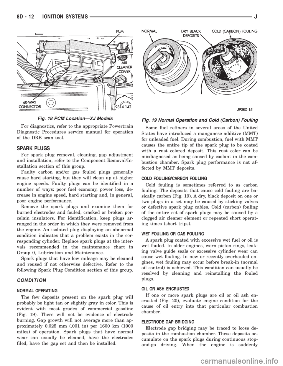
The few deposits present on the spark plug will
probably be light tan or slightly gray in color. This is
evident with most grades of commercial gasoline
(Fig. 19). There will not be evidence of electrode
burning. Gap growth will not average more than ap-
proximately 0.025 mm (.001 in) per 1600 km (1000
miles) of operation. Spark plugs that have normal
wear can usually be cleaned, have the electrodes
filed, have the gap set and then be installed.Some fuel refiners in several areas of the United
States have introduced a manganese additive (MMT)
for unleaded fuel. During combustion, fuel with MMT
causes the entire tip of the spark plug to be coated
with a rust colored deposit. This rust color can be
misdiagnosed as being caused by coolant in the com-
bustion chamber. Spark plug performance is not af-
fected by MMT deposits.
COLD FOULING/CARBON FOULING
Cold fouling is sometimes referred to as carbon
fouling. The deposits that cause cold fouling are ba-
sically carbon (Fig. 19). A dry, black deposit on one or
two plugs in a set may be caused by sticking valves
or defective spark plug cables. Cold (carbon) fouling
of the entire set of spark plugs may be caused by a
clogged air cleaner element or repeated short operat-
ing times (short trips).
WET FOULING OR GAS FOULING
A spark plug coated with excessive wet fuel or oil is
wet fouled. In older engines, worn piston rings, leak-
ing valve guide seals or excessive cylinder wear can
cause wet fouling. In new or recently overhauled en-
gines, wet fouling may occur before break-in (normal
oil control) is achieved. This condition can usually be
resolved by cleaning and reinstalling the fouled
plugs.
OIL OR ASH ENCRUSTED
If one or more spark plugs are oil or oil ash en-
crusted (Fig. 20), evaluate engine condition for the
cause of oil entry into that particular combustion
chamber.
ELECTRODE GAP BRIDGING
Electrode gap bridging may be traced to loose de-
posits in the combustion chamber. These deposits ac-
cumulate on the spark plugs during continuous stop-
and-go driving. When the engine is suddenly
Fig. 18 PCM LocationÐXJ ModelsFig. 19 Normal Operation and Cold (Carbon) Fouling
8D - 12 IGNITION SYSTEMSJ
Page 1093 of 2198
minutes). The use of a locating dowel is recom-
mended during assembly to prevent smearing the
material off location.
Mopar Gasket Maker should be applied sparingly
to one gasket surface. The sealant diameter should
be 1.00 mm (0.04 inch) or less. Be certain the mate-
rial surrounds each mounting hole. Excess material
can easily be wiped off. Components should be
torqued in place within 15 minutes. The use of a lo-
cating dowel is recommended during assembly to pre-
vent smearing the material off location.
ENGINE PERFORMANCE
To provide best vehicle performance and lowest ve-
hicle emissions, it is most important that the tune-up
be done accurately. Use the specifications listed on
the Vehicle Emission Control Information label found
on the engine compartment hood.
(1) Test battery specific gravity. Add water, if nec-
essary. Clean and tighten battery connections.
(2) Test cranking amperage draw (refer to Group
8B, Battery/Starter Service for the proper proce-
dures).
(3) Tighten the intake manifold bolts (refer to
Group 11, Exhaust System and Intake Manifold for
the proper specifications).
(4) Perform cylinder compression test:
(a) Check engine oil level and add oil, if neces-
sary.
(b) Drive the vehicle until engine reaches normal
operating temperature.
(c) Select a route free from traffic and other
forms of congestion, observe all traffic laws and
briskly accelerate through the gears several times.
The higher engine speed may help clean out valve
seat deposits which can prevent accurate compres-
sion readings.
CAUTION: DO NOT overspeed the engine.
(d) Remove all spark plugs from engine. As spark
plugs are being removed, check electrodes for ab-
normal firing indicatorsÐfouled, hot, oily, etc.
Record cylinder number of spark plug for future
reference.
(e) Disconnect coil wire from distributor and se-
cure to good ground to prevent a spark from start-
ing a fire.
(f) Be sure throttle blades are fully open during
the compression check.
(g) Insert compression gage adaptor into the
No.1 spark plug hole. Crank engine until maximum
pressure is reached on gauge. Record this pressure
as No.1 cylinder pressure.
(h) Repeat Step 4g for all remaining cylinders.
(i) Compression should not be less than 689 kPa
(100 psi) and not vary more than 172 kPa (25 psi)
from cylinder to cylinder.(j) If cylinder(s) have abnormally low compres-
sion pressures, repeat steps 4a through 4h.
(k) If the same cylinder(s) repeat an abnormally
low reading, it could indicate the existence of a
problem in the cylinder.
The recommended compression pressures are
to be used only as a guide to diagnosing engine
problems. An engine should NOT be disassem-
bled to determine the cause of low compression
unless some malfunction is present.
(5) Clean or replace spark plugs as necessary. Ad-
just gap (refer to Group 8D, Ignition System for gap
adjustment and torque).
(6) Test resistance of spark plug cables (refer to
Group 8D, Ignition System).
(7) Inspect the primary wire. Test coil output volt-
age, primary and secondary resistance. Replace parts
as necessary (refer to Group 8D, Ignition System and
make necessary adjustment).
(8) Perform a combustion analysis.
(9) Test fuel pump for pressure (refer to Group 14,
Fuel System for the proper specifications).
(10) Inspect air filter element (refer to Group 0,
Lubrication and Maintenance for the proper proce-
dure).
(11) Inspect crankcase ventilation system (refer to
Group 0, Lubrication and Maintenance for the proper
procedure).
(12) For emission controls refer to Group 25, Emis-
sion Controls System for service procedures.
(13) Inspect and adjust accessory belt drives (refer
to Group 7, Cooling System for the proper adjust-
ments).
(14) Road test vehicle as a final test.
HONING CYLINDER BORES
Before honing, stuff plenty of clean shop towels un-
der the bores and over the crankshaft to keep abra-
sive materials from entering the crankshaft area.
(1) Used carefully, the Cylinder Bore Sizing Hone
C-823 equipped with 220 grit stones, is the best tool
for this job. In addition to deglazing, it will reduce
taper and out-of-round as well as removing light
scuffing, scoring or scratches. Usually a few strokes
will clean up a bore and maintain the required lim-
its.
CAUTION: DO NOT use rigid type hones to remove
cylinder wall glaze.
(2) Deglazing of the cylinder walls may be done if
the cylinder bore is straight and round. Use a cylin-
der surfacing hone, Honing Tool C-3501, equipped
with 280 grit stones (C-3501-3810). 20-60 strokes, de-
pending on the bore condition, will be sufficient to
provide a satisfactory surface. Using honing oil
C-3501-3880 or a light honing oil available from ma-
jor oil distributors.
9 - 2 ENGINESJ
Page 1095 of 2198
CONNECTING ROD BEARING CLEARANCE
Engine connecting rod bearing clearances can be
determined by use of Plastigage, or equivalent. The
following is the recommended procedures for the use
of Plastigage:
(1) Remove oil film from surface to be checked.
Plastigage is soluble in oil.
(2) Place a piece of Plastigage across the entire width
of the bearing cap shell (Fig. 2). Position the Plastigage
approximately 6.35 mm (1/4 inch) off center and away
from the oil holes. In addition, suspect areas can be
checked by placing the Plastigage in the suspect area.
(3) The crankshaft must be turned until the connect-
ing rod to be checked starts moving toward the top of
the engine. Only then should the rod cap with Plasti-
gage in place be assembled. Tighten the rod cap nut to
45 Nzm (33 ft. lbs.) torque.DO NOT rotate the crank-
shaft or the Plastigage may be smeared, giving in-
accurate results.
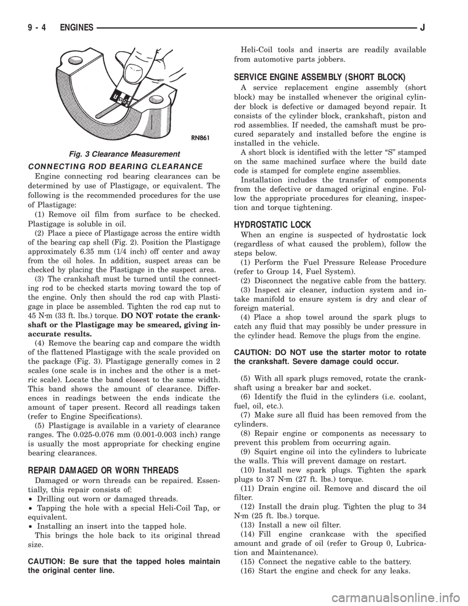
(4) Remove the bearing cap and compare the width
of the flattened Plastigage with the scale provided on
the package (Fig. 3). Plastigage generally comes in 2
scales (one scale is in inches and the other is a met-
ric scale). Locate the band closest to the same width.
This band shows the amount of clearance. Differ-
ences in readings between the ends indicate the
amount of taper present. Record all readings taken
(refer to Engine Specifications).
(5) Plastigage is available in a variety of clearance
ranges. The 0.025-0.076 mm (0.001-0.003 inch) range
is usually the most appropriate for checking engine
bearing clearances.
REPAIR DAMAGED OR WORN THREADS
Damaged or worn threads can be repaired. Essen-
tially, this repair consists of:
²Drilling out worn or damaged threads.
²Tapping the hole with a special Heli-Coil Tap, or
equivalent.
²Installing an insert into the tapped hole.
This brings the hole back to its original thread
size.
CAUTION: Be sure that the tapped holes maintain
the original center line.Heli-Coil tools and inserts are readily available
from automotive parts jobbers.
SERVICE ENGINE ASSEMBLY (SHORT BLOCK)
A service replacement engine assembly (short
block) may be installed whenever the original cylin-
der block is defective or damaged beyond repair. It
consists of the cylinder block, crankshaft, piston and
rod assemblies. If needed, the camshaft must be pro-
cured separately and installed before the engine is
installed in the vehicle.
A short block is identified with the letter ``S'' stamped
on the same machined surface where the build date
code is stamped for complete engine assemblies.
Installation includes the transfer of components
from the defective or damaged original engine. Fol-
low the appropriate procedures for cleaning, inspec-
tion and torque tightening.
HYDROSTATIC LOCK
When an engine is suspected of hydrostatic lock
(regardless of what caused the problem), follow the
steps below.
(1) Perform the Fuel Pressure Release Procedure
(refer to Group 14, Fuel System).
(2) Disconnect the negative cable from the battery.
(3) Inspect air cleaner, induction system and in-
take manifold to ensure system is dry and clear of
foreign material.
(4) Place a shop towel around the spark plugs to
catch any fluid that may possibly be under pressure in
the cylinder head. Remove the plugs from the engine.
CAUTION: DO NOT use the starter motor to rotate
the crankshaft. Severe damage could occur.
(5) With all spark plugs removed, rotate the crank-
shaft using a breaker bar and socket.
(6) Identify the fluid in the cylinders (i.e. coolant,
fuel, oil, etc.).
(7) Make sure all fluid has been removed from the
cylinders.
(8) Repair engine or components as necessary to
prevent this problem from occurring again.
(9) Squirt engine oil into the cylinders to lubricate
the walls. This will prevent damage on restart.
(10) Install new spark plugs. Tighten the spark
plugs to 37 Nzm (27 ft. lbs.) torque.
(11) Drain engine oil. Remove and discard the oil
filter.
(12) Install the drain plug. Tighten the plug to 34
Nzm (25 ft. lbs.) torque.
(13) Install a new oil filter.
(14) Fill engine crankcase with the specified
amount and grade of oil (refer to Group 0, Lubrica-
tion and Maintenance).
(15) Connect the negative cable to the battery.
(16) Start the engine and check for any leaks.
Fig. 3 Clearance Measurement
9 - 4 ENGINESJ