1995 JEEP CHEROKEE Maintenance
[x] Cancel search: MaintenancePage 1142 of 2198
ASSEMBLY
Refer to the applicable sections for detailed instruc-
tions.
(1) Install the crankshaft.
(2) Install the connecting rods and the pistons
through the top of the cylinder bores.
(3) Install the front and rear oil galley plugs.
(4) Install the timing chain tensioner.
(5) Install the camshaft.
(6) Install the sprockets and chain as an assembly.
(7) Install the oil slinger to the crankshaft.
(8) Install the timing chain bumper.
(9) Install the timing case cover seal.
(10) Install the timing case cover.(11) Install the oil pan gasket and oil pan.
(12) Install the vibration damper.
(13) Install the water pump. Tighten the mounting
bolts to 31 Nzm (270 in. lbs.) torque.
(14) Remove the distributor from the cylinder
block.
(15) Lubricate the oil filter seal with clean engine
oil. Tighten oil filter to 18 Nzm (13 ft. lbs.) torque.
(16) Install the engine into the vehicle.
(17) Fill the engine with clean lubrication oil (refer
to Group 0, Lubrication and Maintenance).
(18) Fill the cooling system (refer to Group 7, Cool-
ing System for the proper procedures).
J2.5L ENGINE 9 - 51
Page 1183 of 2198
²The front and rear oil galley holes.
²The feed holes for the crankshaft main bearings.
Once the block has been completely cleaned, apply
Loctite PST pipe sealant with Teflon 592 to the
threads of the front and rear oil galley plugs. Tighten
the plugs to 41 Nzm (30 ft. lbs.) torque.
INSPECTIONÐCYLINDER BORE
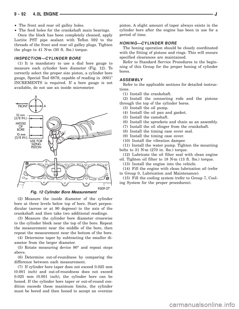
(1) It is mandatory to use a dial bore gauge to
measure each cylinder bore diameter (Fig. 12). To
correctly select the proper size piston, a cylinder bore
gauge, Special Tool 6879, capable of reading in .00019
INCREMENTS is required. If a bore gauge is not
available, do not use an inside micrometer.
(2) Measure the inside diameter of the cylinder
bore at three levels below top of bore. Start perpen-
dicular (across or at 90 degrees) to the axis of the
crankshaft and then take two additional readings.
(3) Measure the cylinder bore diameter crosswise
to the cylinder block near the top of the bore. Repeat
the measurement near the middle of the bore, then
repeat the measurement near the bottom of the bore.
(4) Determine taper by subtracting the smaller di-
ameter from the larger diameter.
(5) Rotate measuring device 90É and repeat steps
above.
(6) Determine out-of-roundness by comparing the
difference between each measurement.
(7) If cylinder bore taper does not exceed 0.025 mm
(0.001 inch) and out-of-roundness does not exceed
0.025 mm (0.001 inch), the cylinder bore can be
honed. If the cylinder bore taper or out-of-round con-
dition exceeds these maximum limits, the cylinder
must be bored and then honed to accept an oversizepiston. A slight amount of taper always exists in the
cylinder bore after the engine has been in use for a
period of time.
HONINGÐCYLINDER BORE
The honing operation should be closely coordinated
with the fitting of pistons and rings. This will ensure
specified clearances are maintained.
Refer to Standard Service Procedures in the begin-
ning of this Group for the proper honing of cylinder
bores.
ASSEMBLY
Refer to the applicable sections for detailed instruc-
tions.
(1) Install the crankshaft.
(2) Install the connecting rods and the pistons
through the top of the cylinder bores.
(3) Install the oil pump.
(4) Install the oil pan and gasket.
(5) Install the camshaft.
(6) Install the sprockets and chain as an assembly.
(7) Install the oil slinger from the crankshaft.
(8) Install the timing case cover seal.
(9) Install the timing case cover.
(10) Install the vibration damper.
(11) Install the water pump. Tighten the mounting
bolts to 31 Nzm (270 in. lbs.) torque.
(12) Lubricate the oil filter seal with clean engine
oil. Tighten oil filter to 18 Nzm (13 ft. lbs.) torque.
(13) Install the engine into the vehicle.
(14) Fill the engine with clean lubrication oil (refer
to Group 0, Lubrication and Maintenance).
(15) Fill the cooling system (refer to Group 7, Cool-
ing System for the proper procedures).
Fig. 12 Cylinder Bore Measurement
9 - 92 4.0L ENGINEJ
Page 1224 of 2198
codes are not displayed, the problem may be mechan-
ical rather than electronic.
FUEL FILTER
The fuel filter protects the fuel injectors and fuel
pressure regulator from dirt, water and other foreign
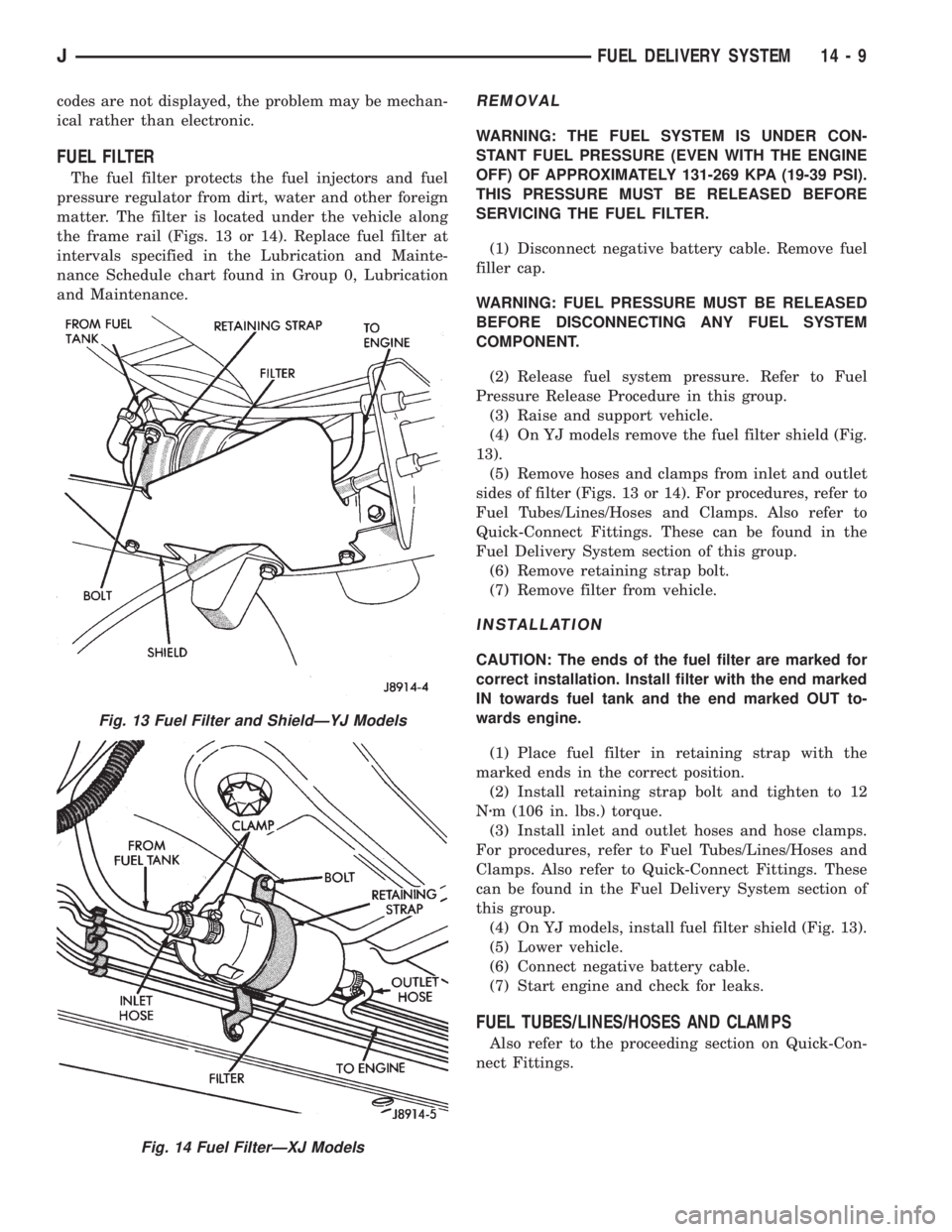
matter. The filter is located under the vehicle along
the frame rail (Figs. 13 or 14). Replace fuel filter at
intervals specified in the Lubrication and Mainte-
nance Schedule chart found in Group 0, Lubrication
and Maintenance.
REMOVAL
WARNING: THE FUEL SYSTEM IS UNDER CON-
STANT FUEL PRESSURE (EVEN WITH THE ENGINE
OFF) OF APPROXIMATELY 131-269 KPA (19-39 PSI).
THIS PRESSURE MUST BE RELEASED BEFORE
SERVICING THE FUEL FILTER.
(1) Disconnect negative battery cable. Remove fuel
filler cap.
WARNING: FUEL PRESSURE MUST BE RELEASED
BEFORE DISCONNECTING ANY FUEL SYSTEM
COMPONENT.
(2) Release fuel system pressure. Refer to Fuel
Pressure Release Procedure in this group.
(3) Raise and support vehicle.
(4) On YJ models remove the fuel filter shield (Fig.
13).
(5) Remove hoses and clamps from inlet and outlet
sides of filter (Figs. 13 or 14). For procedures, refer to
Fuel Tubes/Lines/Hoses and Clamps. Also refer to
Quick-Connect Fittings. These can be found in the
Fuel Delivery System section of this group.
(6) Remove retaining strap bolt.
(7) Remove filter from vehicle.
INSTALLATION
CAUTION: The ends of the fuel filter are marked for
correct installation. Install filter with the end marked
IN towards fuel tank and the end marked OUT to-
wards engine.
(1) Place fuel filter in retaining strap with the
marked ends in the correct position.
(2) Install retaining strap bolt and tighten to 12
Nzm (106 in. lbs.) torque.
(3) Install inlet and outlet hoses and hose clamps.
For procedures, refer to Fuel Tubes/Lines/Hoses and
Clamps. Also refer to Quick-Connect Fittings. These
can be found in the Fuel Delivery System section of
this group.
(4) On YJ models, install fuel filter shield (Fig. 13).
(5) Lower vehicle.
(6) Connect negative battery cable.
(7) Start engine and check for leaks.
FUEL TUBES/LINES/HOSES AND CLAMPS
Also refer to the proceeding section on Quick-Con-
nect Fittings.
Fig. 13 Fuel Filter and ShieldÐYJ Models
Fig. 14 Fuel FilterÐXJ Models
JFUEL DELIVERY SYSTEM 14 - 9
Page 1476 of 2198
30RH/32RH IN-VEHICLE SERVICE
INDEX
page page
Converter Drainback Check Valve Service...... 113
Fluid and Filter Replacement................. 99
Fluid Level Check......................... 99
Front Band Adjustment.................... 102
Governor and Park Gear Service............. 105
Oil Filter Replacement..................... 103
Park Interlock Cable Adjustment (XJ).......... 101
Park Lock Component Replacement.......... 108
Park/Neutral Position Switch Service.......... 109
Rear Band Adjustment.................... 103
Recommended Fluid....................... 99Refilling After Overhaul or Fluid/Filter Change . . . 100
Shift Cable Adjustment (XJ)................. 100
Shift Linkage Adjustment (YJ)............... 100
Speedometer Service..................... 109
Throttle Valve Cable Adjustment (XJ/YJ)....... 101
Transmission Cooler Flow Testing............ 113
Transmission Cooler Line and Fitting Service.... 111
Transmission Cooler Reverse Flushing......... 114
Valve Body Installation.................... 104
Valve Body Removal...................... 104
Valve Body Service....................... 104
RECOMMENDED FLUID
Recommended (and preferred) fluid for 30RH/32RH
transmissions is Mopar ATF Plus, type 7176.
Dexron II is not really recommended and should
only be used when ATF Plus is not available.
FLUID LEVEL CHECK
Transmission fluid level should be checked monthly
under normal operation. If the vehicle is used for
trailer towing or similar heavy load hauling, check
fluid level and condition weekly.
Fluid level is checked with the engine running at
curb idle speed, the transmission in Neutral and the
transmission fluid at normal operating temperature.
FLUID LEVEL CHECK PROCEDURE
(1) Transmission fluid must be at normal operating
temperature for accurate fluid level check. Drive ve-
hicle if necessary to bring fluid temperature up to
normal hot operating temperature of 82ÉC (180ÉF).
(2) Position vehicle on level surface. This is ex-
tremely important for accurate fluid level check.
(3) Start and run engine at curb idle speed.
(4) Apply parking brakes.
(5) Shift transmission momentarily into all gear
ranges. Then shift transmission back to Neutral.
(6) Clean top of filler tube and dipstick to keep dirt
from entering tube.
(7) Remove dipstick and check fluid level as fol-
lows:
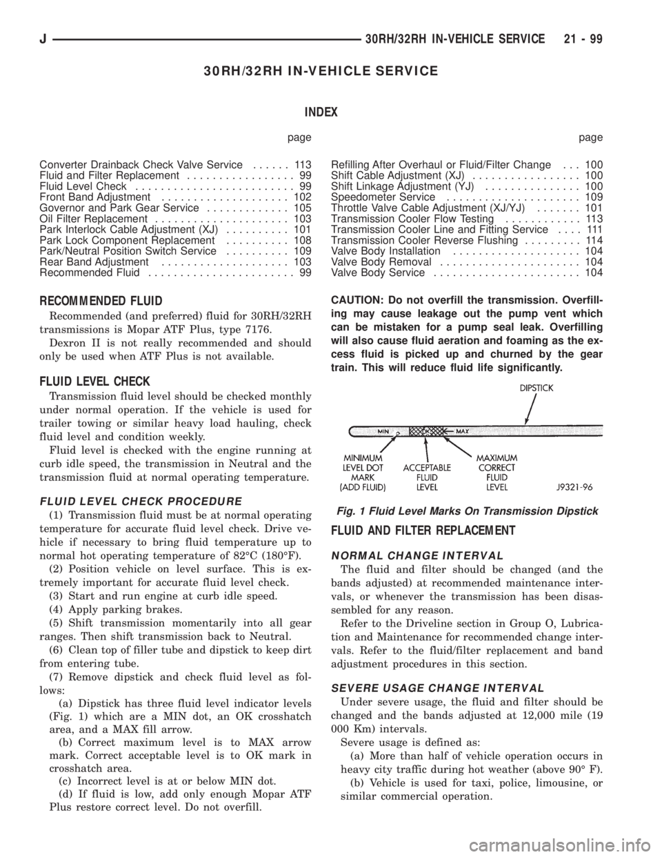
(a) Dipstick has three fluid level indicator levels
(Fig. 1) which are a MIN dot, an OK crosshatch
area, and a MAX fill arrow.
(b) Correct maximum level is to MAX arrow
mark. Correct acceptable level is to OK mark in
crosshatch area.
(c) Incorrect level is at or below MIN dot.
(d) If fluid is low, add only enough Mopar ATF
Plus restore correct level. Do not overfill.CAUTION: Do not overfill the transmission. Overfill-
ing may cause leakage out the pump vent which
can be mistaken for a pump seal leak. Overfilling
will also cause fluid aeration and foaming as the ex-
cess fluid is picked up and churned by the gear
train. This will reduce fluid life significantly.
FLUID AND FILTER REPLACEMENT
NORMAL CHANGE INTERVAL
The fluid and filter should be changed (and the
bands adjusted) at recommended maintenance inter-
vals, or whenever the transmission has been disas-
sembled for any reason.
Refer to the Driveline section in Group O, Lubrica-
tion and Maintenance for recommended change inter-
vals. Refer to the fluid/filter replacement and band
adjustment procedures in this section.
SEVERE USAGE CHANGE INTERVAL
Under severe usage, the fluid and filter should be
changed and the bands adjusted at 12,000 mile (19
000 Km) intervals.
Severe usage is defined as:
(a) More than half of vehicle operation occurs in
heavy city traffic during hot weather (above 90É F).
(b) Vehicle is used for taxi, police, limousine, or
similar commercial operation.
Fig. 1 Fluid Level Marks On Transmission Dipstick
J30RH/32RH IN-VEHICLE SERVICE 21 - 99
Page 1724 of 2198
²Noise
²Handling
²Durability
²Tread life
²Traction
²Rolling resistance
²Speed capability
Original equipment tires should be used when re-
placement is needed.
Refer to the placard on the vehicle or the
Owner's Manual for the correct replacement
tire.
Failure to use original or equivalent replacement
tires may adversely affect the handling of the vehicle.
The use of oversize tiresis not recommended.
They may cause interference with vehicle suspension
and steering travel. This can cause tire damage or
failure.
WARNING: FAILURE TO EQUIP THE VEHICLE WITH
TIRES HAVING ADEQUATE LOAD CAPABILITY CAN
RESULT IN SUDDEN TIRE FAILURE.
ROTATION
Tires on the front and rear axles operate at differ-
ent loads and perform different steering, driving, and
braking functions. For these reasons, the tires wear
at unequal rates. They may also develop irregular
wear patterns. These effects can be reduced by rotat-
ing the tires according to the maintenance schedule
in the Owners Manual. This will improve tread life,
traction and maintain a smooth quiet ride.
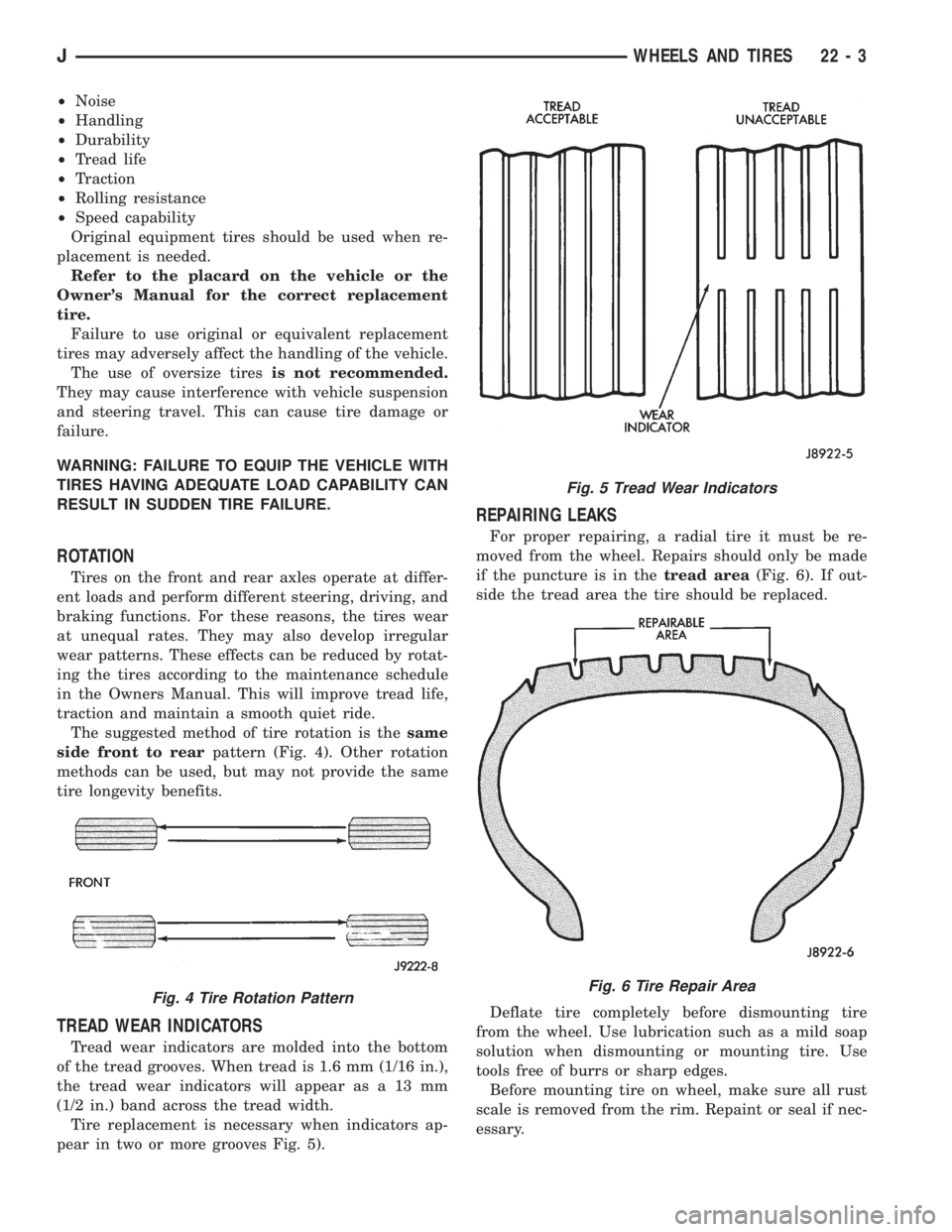
The suggested method of tire rotation is thesame
side front to rearpattern (Fig. 4). Other rotation
methods can be used, but may not provide the same
tire longevity benefits.
TREAD WEAR INDICATORS
Tread wear indicators are molded into the bottom
of the tread grooves. When tread is 1.6 mm (1/16 in.),
the tread wear indicators will appear as a 13 mm
(1/2 in.) band across the tread width.
Tire replacement is necessary when indicators ap-
pear in two or more grooves Fig. 5).
REPAIRING LEAKS
For proper repairing, a radial tire it must be re-
moved from the wheel. Repairs should only be made
if the puncture is in thetread area(Fig. 6). If out-
side the tread area the tire should be replaced.
Deflate tire completely before dismounting tire
from the wheel. Use lubrication such as a mild soap
solution when dismounting or mounting tire. Use
tools free of burrs or sharp edges.
Before mounting tire on wheel, make sure all rust
scale is removed from the rim. Repaint or seal if nec-
essary.
Fig. 4 Tire Rotation Pattern
Fig. 5 Tread Wear Indicators
Fig. 6 Tire Repair Area
JWHEELS AND TIRES 22 - 3
Page 1734 of 2198
BODY COMPONENTSÐXJ VEHICLES
CONTENTS
page page
DOORS................................ 30
EXTERIOR COMPONENTS.................. 3
GENERAL BODY SERVICE INFORMATION..... 1INTERIOR COMPONENTS................. 80
STATIONARY WINDOW GLASS............. 66
TRAILER HITCH......................... 77
GENERAL BODY SERVICE INFORMATION
RIGHT HAND DRIVE VEHICLES
The XJ Body Components procedures in this sec-
tion were developed on a left hand drive (LHD) vehi-
cle. Unless a component is unique to a right hand
drive vehicle, it will not be specifically covered in this
section, i.e. cargo barrier. In general, components on
left hand drive vehicles will be located on the oppo-
site side in right hand drive vehicles.
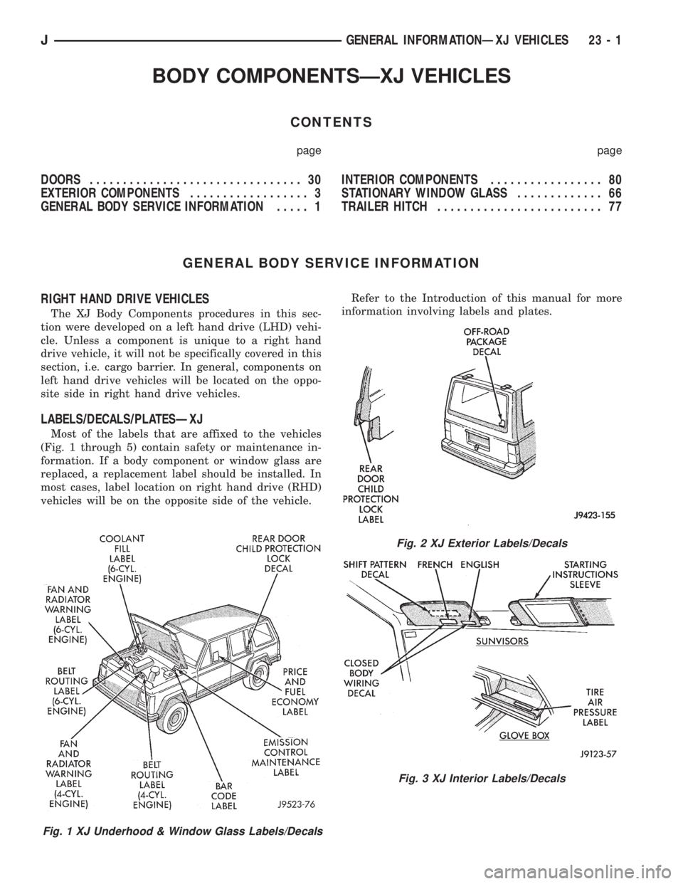
LABELS/DECALS/PLATESÐXJ
Most of the labels that are affixed to the vehicles
(Fig. 1 through 5) contain safety or maintenance in-
formation. If a body component or window glass are
replaced, a replacement label should be installed. In
most cases, label location on right hand drive (RHD)
vehicles will be on the opposite side of the vehicle.Refer to the Introduction of this manual for more
information involving labels and plates.
Fig. 1 XJ Underhood & Window Glass Labels/Decals
Fig. 2 XJ Exterior Labels/Decals
Fig. 3 XJ Interior Labels/Decals
JGENERAL INFORMATIONÐXJ VEHICLES 23 - 1
Page 1874 of 2198
Prior to door adjustment or alignment, the door
latch must be removed to allow the door to close
freely and be properly aligned.
The door latch striker should be adjusted in or out
to allow the door latch to be fully engaged. The door
should be flush with the adjacent body panels.
REPLACEMENT
(1) Mark the outline of the existing hinge on the
body and the door with a wax pencil for installation
alignment reference.
When removing the door or hinge DO NOT
discard the plastic shims or the hinge pin.
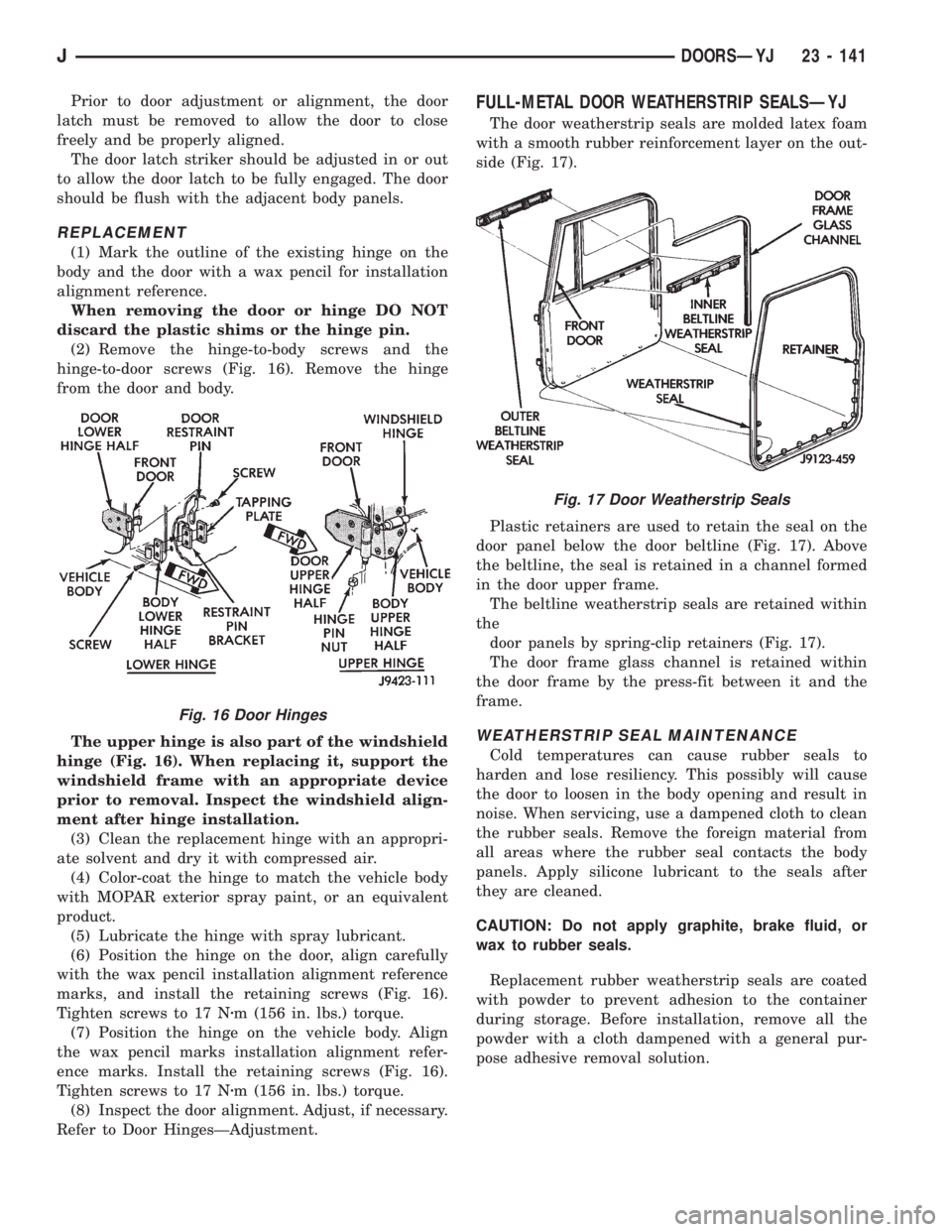
(2) Remove the hinge-to-body screws and the
hinge-to-door screws (Fig. 16). Remove the hinge
from the door and body.
The upper hinge is also part of the windshield
hinge (Fig. 16). When replacing it, support the
windshield frame with an appropriate device
prior to removal. Inspect the windshield align-
ment after hinge installation.
(3) Clean the replacement hinge with an appropri-
ate solvent and dry it with compressed air.
(4) Color-coat the hinge to match the vehicle body
with MOPAR exterior spray paint, or an equivalent
product.
(5) Lubricate the hinge with spray lubricant.
(6) Position the hinge on the door, align carefully
with the wax pencil installation alignment reference
marks, and install the retaining screws (Fig. 16).
Tighten screws to 17 Nzm (156 in. lbs.) torque.
(7) Position the hinge on the vehicle body. Align
the wax pencil marks installation alignment refer-
ence marks. Install the retaining screws (Fig. 16).
Tighten screws to 17 Nzm (156 in. lbs.) torque.
(8) Inspect the door alignment. Adjust, if necessary.
Refer to Door HingesÐAdjustment.
FULL-METAL DOOR WEATHERSTRIP SEALSÐYJ
The door weatherstrip seals are molded latex foam
with a smooth rubber reinforcement layer on the out-
side (Fig. 17).
Plastic retainers are used to retain the seal on the
door panel below the door beltline (Fig. 17). Above
the beltline, the seal is retained in a channel formed
in the door upper frame.
The beltline weatherstrip seals are retained within
the
door panels by spring-clip retainers (Fig. 17).
The door frame glass channel is retained within
the door frame by the press-fit between it and the
frame.
WEATHERSTRIP SEAL MAINTENANCE
Cold temperatures can cause rubber seals to
harden and lose resiliency. This possibly will cause
the door to loosen in the body opening and result in
noise. When servicing, use a dampened cloth to clean
the rubber seals. Remove the foreign material from
all areas where the rubber seal contacts the body
panels. Apply silicone lubricant to the seals after
they are cleaned.
CAUTION: Do not apply graphite, brake fluid, or
wax to rubber seals.
Replacement rubber weatherstrip seals are coated
with powder to prevent adhesion to the container
during storage. Before installation, remove all the
powder with a cloth dampened with a general pur-
pose adhesive removal solution.
Fig. 16 Door Hinges
Fig. 17 Door Weatherstrip Seals
JDOORSÐYJ 23 - 141
Page 1934 of 2198
EMISSION CONTROL SYSTEMS
CONTENTS
page page
COMPONENT REMOVAL/INSTALLATION....... 7
EMISSION CONTROLS.................... 4GENERAL INFORMATION.................. 1
GENERAL INFORMATION
INDEX
page page
Catalytic Convertor......................... 1
DRB Scan Tool............................ 2
Exhaust Gas Recirculation (EGR) System........ 1Service Reminder Indicator (SRI) Lamp.......... 1
Vacuum Hose Routing Schematics............. 2
Vehicle Emission Control Information (VECI) Label . 1
Throughout this group, references are made to par-
ticular vehicle models by alphabetical designation
(XJ or YJ) or by the particular vehicle nameplate. A
chart showing a breakdown of alphabetical designa-
tions is included in the Introduction section at the
beginning of this manual.
Information on the air cleaner housing and the air
cleaner element can be found in Group 14, Fuel Sys-
tems.
CATALYTIC CONVERTOR
Refer to Group 11, Exhaust System and Intake
Manifold for information.
EXHAUST GAS RECIRCULATION (EGR) SYSTEM
An EGR system is not used with the 2.5L 4 cylin-
der or the 4.0L 6 cylinder engine on any XJ or YJ
model.
SERVICE REMINDER INDICATOR (SRI) LAMP
The instrument panel mounted SRI lamp was for-
merly referred to as the emission maintenance re-
minder (EMR) lamp. It isnot usedon any XJ or YJ
model for the 1995 model year.
VEHICLE EMISSION CONTROL INFORMATION
(VECI) LABEL
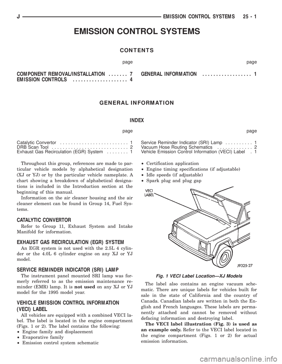
All vehicles are equipped with a combined VECI la-
bel. The label is located in the engine compartment
(Figs. 1 or 2). The label contains the following:
²Engine family and displacement
²Evaporative family
²Emission control system schematic²Certification application
²Engine timing specifications (if adjustable)
²Idle speeds (if adjustable)
²Spark plug and plug gap
The label also contains an engine vacuum sche-
matic. There are unique labels for vehicles built for
sale in the state of California and the country of
Canada. Canadian labels are written in both the En-
glish and French languages. These labels are perma-
nently attached and cannot be removed without
defacing information and destroying label.
The VECI label illustration (Fig. 3) is used as
an example only.Refer to the VECI label located in
the engine compartment (Figs. 1 or 2) for actual
emission information.
Fig. 1 VECI Label LocationÐXJ Models
JEMISSION CONTROL SYSTEMS 25 - 1