1995 JEEP CHEROKEE oil change
[x] Cancel search: oil changePage 926 of 2198
HEATED REAR WINDOW
HEATED REAR WINDOW
The heated rear window relay supplies power to
heated rear window grid. Circuit F83 from fuse 14 in
the fuse block supplies power to the heated rear win-
dow relay when the ignition switch is in the ACCES-
SORY OR RUN positions.
When the operator depresses the heated rear win-
dow switch, the contacts inside the switch momen-
tarily close and circuit C80 connects the switch to the
relay. This causes the relay to change state and com-
plete a circuit to energize the coil side of the relay
and start the relay timer.
Circuit F82 from fuse 7 in the Power Distribution
Center (PDC) supplies voltage to the coil and contact
sides of the relay. Circuit Z1 provides ground for the
relay.
When the heated rear window relay energizes, the
contacts inside the relay close and connect circuit
F82 to circuit C15. Circuit C15 splices to the power
the heated rear window grid and the indicator lamp
in the heated rear window switch. Circuit Z1 pro-
vides ground for the heated rear window grid.
HELPFUL INFORMATION
²When the ignition switch is in the ACCESSORY or
RUN positions, it connects circuit A1 from fuse 11 in
the power distribution center (PDC) to circuit A48.
²Check for broken grid lines on the window.
²Check for a broken bus bar or disconnected leads
at the rear window.
²Check for a good ground.
DIAGRAM INDEX
Component Page
Fuse 2 (Fuse Block).......................8W-48-2
Fuse 6 (PDC)...........................8W-48-2
Fuse 7 (PDC)...........................8W-48-2
Fuse 14 (Fuse Block)......................8W-48-2
Ignition Switch..........................8W-48-2
Heated Rear Window Grid...................8W-48-3
Heated Rear Window Relay..................8W-48-2
Heated Rear Window Switch.................8W-48-2
J8W-48 HEATED REAR WINDOWÐXJ-RHD 8W - 48 - 1
Page 1092 of 2198
ENGINES
CONTENTS
page page
LUBRICATION SYSTEM................... 37
LUBRICATION SYSTEM................... 79
2.5L ENGINE SERVICE PROCEDURES....... 134.0L ENGINE SERVICE PROCEDURES....... 55
ENGINE DIAGNOSIS...................... 5
STANDARD SERVICE PROCEDURES......... 1
STANDARD SERVICE PROCEDURES
INDEX
page page
Engine Performance........................ 2
Form-In-Place Gaskets...................... 1
Honing Cylinder Bores...................... 2
Hydrostatic Lock........................... 4Measuring with Plastigage.................... 3
Repair Damaged or Worn Threads............. 4
Service Engine Assembly (Short Block).......... 4
FORM-IN-PLACE GASKETS
There are several places where form-in-place gas-
kets are used on the engine.DO NOT use form-in-
place gasket material unless specified.Care
must be taken when applying form-in-place gaskets.
Bead size, continuity and location are of great impor-
tance. Too thin a bead can result in leakage while too
much can result in spill-over. A continuous bead of
the proper width is essential to obtain a leak-free
joint.
Two types of form-in-place gasket materials are
used in the engine area (Mopar Silicone Rubber Ad-
hesive Sealant and Mopar Gasket Maker). Each have
different properties and cannot be used interchange-
ably.
MOPAR SILICONE RUBBER ADHESIVE
SEALANT
Mopar Silicone Rubber Adhesive Sealant, normally
black in color, is available in 3 ounce tubes. Moisture
in the air causes the sealant material to cure. This
material is normally used on flexible metal flanges.
It has a shelf life of a year and will not properly cure
if over aged. Always inspect the package for the ex-
piration date before use.
MOPAR GASKET MAKER
Mopar Gasket Maker, normally red in color, is
available in 6 cc tubes. This anaerobic type gasket
material cures in the absence of air when squeezedbetween smooth machined metallic surfaces. It will
not cure if left in the uncovered tube. DO NOT use
on flexible metal flanges.
SURFACE PREPARATION
Parts assembled with form-in-place gaskets may be
disassembled without unusual effort. In some in-
stances, it may be necessary to lightly tap the part
with a mallet or other suitable tool to break the seal
between the mating surfaces. A flat gasket scraper
may also be lightly tapped into the joint but care
must be taken not to damage the mating surfaces.
Scrape or wire brush all gasket surfaces to remove
all loose material. Inspect stamped parts to ensure
gasket rails are flat. Flatten rails with a hammer on
a flat plate, if required. Gasket surfaces must be free
of oil and dirt. Make sure the old gasket material is
removed from blind attaching holes.
GASKET APPLICATION
Assembling parts using a form-in-place gasket re-
quires care.
Mopar Silicone Rubber Adhesive Sealant should be
applied in a continuous bead approximately 3 mm
(0.12 inch) in diameter. All mounting holes must be
circled. For corner sealing,a3or6mm(1/8 or 1/4
inch) drop is placed in the center of the gasket con-
tact area. Uncured sealant may be removed with a
shop towel. Components should be torqued in place
while the sealant is still wet to the touch (within 10
JENGINES 9 - 1
Page 1096 of 2198
ENGINE DIAGNOSIS
Engine diagnosis is helpful in determining the
causes of malfunctions not detected and remedied by
routine tune-ups.
These malfunctions may be classified as either per-
formance (e.g., engine idles rough and stalls) or me-
chanical (e.g., a strange noise).
Refer to the Service DiagnosisÐPerformance chart
and the Service DiagnosisÐMechanical chart for pos-
sible causes and corrections of malfunctions. Refer to
Group 14, Fuel System for the fuel system diagnosis.
GENERAL INFORMATION
Additional tests and diagnostic procedures may be
necessary for specific engine malfunctions that can
not be isolated with the Service Diagnosis charts. In-
formation concerning additional tests and diagnosis
is provided within the following diagnosis:
²Cylinder Compression Pressure Test.
²Cylinder Combustion Pressure Leakage Test.
²Engine Cylinder Head Gasket Failure Diagnosis.
²Intake Manifold Leakage Diagnosis.
INTAKE MANIFOLD LEAKAGE DIAGNOSIS
An intake manifold air leak is characterized by
lower than normal manifold vacuum. Also, one or
more cylinders may not be functioning.
WARNING: USE EXTREME CAUTION WHEN THE
ENGINE IS OPERATING. DO NOT STAND IN A DI-
RECT LINE WITH THE FAN. DO NOT PUT YOUR
HANDS NEAR THE PULLEYS, BELTS OR THE FAN.
DO NOT WEAR LOOSE CLOTHING.
METHOD 1
(1) Start the engine.
(2) Spray a small stream of water at the suspected
leak area.
(3) If a change in RPM'S, the area of the suspected
leak has been found.
(4) Repair as required.
CYLINDER COMPRESSION PRESSURE TEST
The results of a cylinder compression pressure test
can be utilized to diagnose several engine malfunc-
tions.
Ensure the battery is completely charged and the
engine starter motor is in good operating condition.
Otherwise the indicated compression pressures may
not be valid for diagnosis purposes.
(1) Clean the spark plug recesses with compressed
air.
(2) Remove the spark plugs.
(3) Secure the throttle in the wide-open position.
(4) Disconnect the ignition coil.(5) Insert a compression pressure gauge and rotate
the engine with the engine starter motor for three
revolutions.
(6) Record the compression pressure on the 3rd
revolution. Continue the test for the remaining cylin-
ders.
Refer to Engine Specifications for the correct en-
gine compression pressures.
ENGINE CYLINDER HEAD GASKET FAILURE
DIAGNOSIS
A leaking engine cylinder head gasket usually re-
sults in loss of power, loss of coolant and engine mis-
firing.
An engine cylinder head gasket leak can be located
between adjacent cylinders or between a cylinder and
the adjacent water jacket.
²An engine cylinder head gasket leaking between
adjacent cylinders is indicated by a loss of power
and/or engine misfire.
²An engine cylinder head gasket leaking between a
cylinder and an adjacent water jacket is indicated by
coolant foaming or overheating and loss of coolant.
CYLINDER-TO-CYLINDER LEAKAGE TEST
To determine if an engine cylinder head gasket is
leaking between adjacent cylinders; follow the proce-
dures outlined in Cylinder Compression Pressure
Test. An engine cylinder head gasket leaking between
adjacent cylinders will result in approximately a 50-
70% reduction in compression pressure.
CYLINDER-TO-WATER JACKET LEAKAGE
TEST
WARNING: USE EXTREME CAUTION WHEN THE
ENGINE IS OPERATING. DO NOT STAND IN A DI-
RECT LINE WITH THE FAN. DO NOT PUT YOUR
HANDS NEAR THE PULLEYS, BELTS OR THE FAN.
DO NOT WEAR LOOSE CLOTHING.
Remove the radiator cap.
Start the engine and allow it to warm up until the
engine thermostat opens.
If a large combustion/compression pressure leak ex-
ists, bubbles will be visible in the coolant.
If bubbles are not visible, install a radiator pres-
sure tester and pressurize the coolant system.
If a cylinder is leaking combustion pressure into
the water jacket, the tester pointer will pulsate with
every combustion stroke of the cylinder.
JENGINES 9 - 5
Page 1116 of 2198
LEAK-DOWN TEST
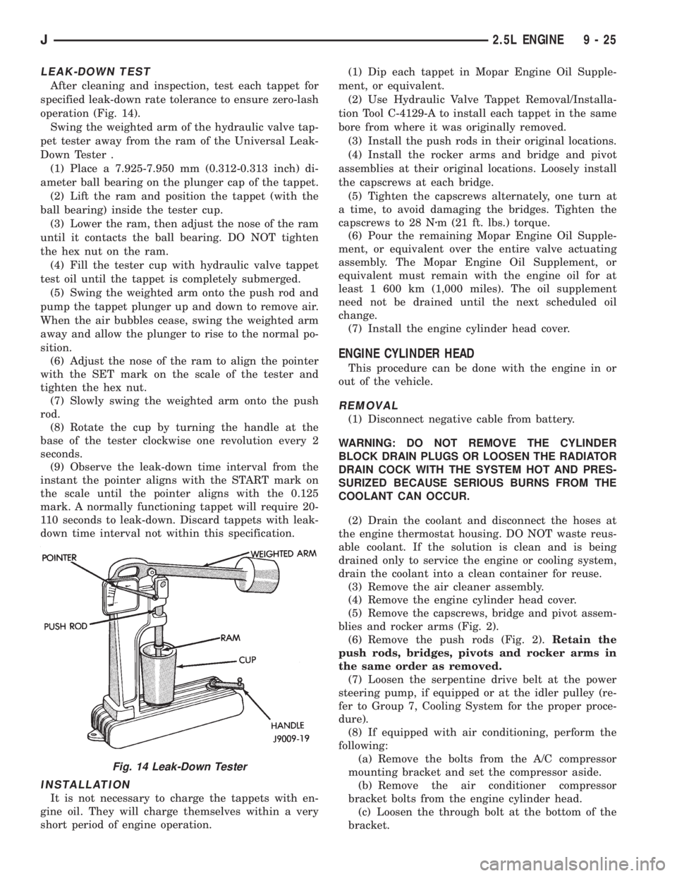
After cleaning and inspection, test each tappet for
specified leak-down rate tolerance to ensure zero-lash
operation (Fig. 14).
Swing the weighted arm of the hydraulic valve tap-
pet tester away from the ram of the Universal Leak-
Down Tester .
(1) Place a 7.925-7.950 mm (0.312-0.313 inch) di-
ameter ball bearing on the plunger cap of the tappet.
(2) Lift the ram and position the tappet (with the
ball bearing) inside the tester cup.
(3) Lower the ram, then adjust the nose of the ram
until it contacts the ball bearing. DO NOT tighten
the hex nut on the ram.
(4) Fill the tester cup with hydraulic valve tappet
test oil until the tappet is completely submerged.
(5) Swing the weighted arm onto the push rod and
pump the tappet plunger up and down to remove air.
When the air bubbles cease, swing the weighted arm
away and allow the plunger to rise to the normal po-
sition.
(6) Adjust the nose of the ram to align the pointer
with the SET mark on the scale of the tester and
tighten the hex nut.
(7) Slowly swing the weighted arm onto the push
rod.
(8) Rotate the cup by turning the handle at the
base of the tester clockwise one revolution every 2
seconds.
(9) Observe the leak-down time interval from the
instant the pointer aligns with the START mark on
the scale until the pointer aligns with the 0.125
mark. A normally functioning tappet will require 20-
110 seconds to leak-down. Discard tappets with leak-
down time interval not within this specification.
INSTALLATION
It is not necessary to charge the tappets with en-
gine oil. They will charge themselves within a very
short period of engine operation.(1) Dip each tappet in Mopar Engine Oil Supple-
ment, or equivalent.
(2) Use Hydraulic Valve Tappet Removal/Installa-
tion Tool C-4129-A to install each tappet in the same
bore from where it was originally removed.
(3) Install the push rods in their original locations.
(4) Install the rocker arms and bridge and pivot
assemblies at their original locations. Loosely install
the capscrews at each bridge.
(5) Tighten the capscrews alternately, one turn at
a time, to avoid damaging the bridges. Tighten the
capscrews to 28 Nzm (21 ft. lbs.) torque.
(6) Pour the remaining Mopar Engine Oil Supple-
ment, or equivalent over the entire valve actuating
assembly. The Mopar Engine Oil Supplement, or
equivalent must remain with the engine oil for at
least 1 600 km (1,000 miles). The oil supplement
need not be drained until the next scheduled oil
change.
(7) Install the engine cylinder head cover.
ENGINE CYLINDER HEAD
This procedure can be done with the engine in or
out of the vehicle.
REMOVAL
(1) Disconnect negative cable from battery.
WARNING: DO NOT REMOVE THE CYLINDER
BLOCK DRAIN PLUGS OR LOOSEN THE RADIATOR
DRAIN COCK WITH THE SYSTEM HOT AND PRES-
SURIZED BECAUSE SERIOUS BURNS FROM THE
COOLANT CAN OCCUR.
(2) Drain the coolant and disconnect the hoses at
the engine thermostat housing. DO NOT waste reus-
able coolant. If the solution is clean and is being
drained only to service the engine or cooling system,
drain the coolant into a clean container for reuse.
(3) Remove the air cleaner assembly.
(4) Remove the engine cylinder head cover.
(5) Remove the capscrews, bridge and pivot assem-
blies and rocker arms (Fig. 2).
(6) Remove the push rods (Fig. 2).Retain the
push rods, bridges, pivots and rocker arms in
the same order as removed.
(7) Loosen the serpentine drive belt at the power
steering pump, if equipped or at the idler pulley (re-
fer to Group 7, Cooling System for the proper proce-
dure).
(8) If equipped with air conditioning, perform the
following:
(a) Remove the bolts from the A/C compressor
mounting bracket and set the compressor aside.
(b) Remove the air conditioner compressor
bracket bolts from the engine cylinder head.
(c) Loosen the through bolt at the bottom of the
bracket.
Fig. 14 Leak-Down Tester
J2.5L ENGINE 9 - 25
Page 1133 of 2198
SIDE CLEARANCE MEASUREMENT
Slide snug-fitting feeler gauge between the connect-
ing rod and crankshaft journal flange. Refer to En-
gine Specifications for the proper clearance. Replace
the connecting rod if the side clearance is not within
specification.
PISTON FITTING
BORE GAUGE METHOD
(1) To correctly select the proper size piston, a cyl-
inder bore gauge, Special Tool 6879 or equivalent, ca-
pable of reading in .00019INCREMENTS with gauge
ring Special Tool 6884 is required. If a bore gauge is
not available, do not use an inside micrometer.
(2) Set the bore gauge to the gauge ring and zero
gauge.
(3) Remove gauge from ring and check cylinder as
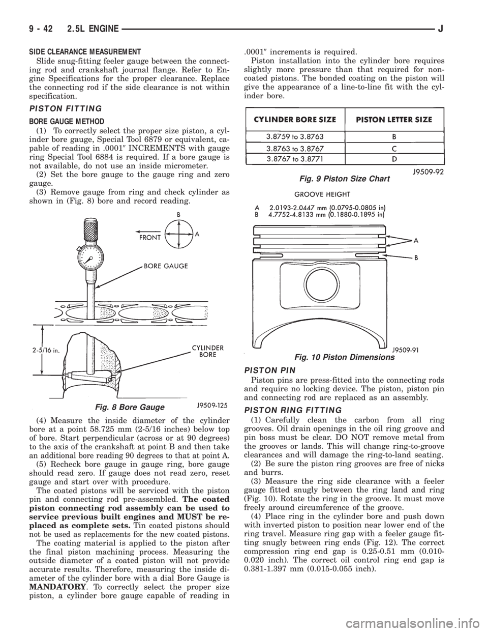
shown in (Fig. 8) bore and record reading.
(4) Measure the inside diameter of the cylinder
bore at a point 58.725 mm (2-5/16 inches) below top
of bore. Start perpendicular (across or at 90 degrees)
to the axis of the crankshaft at point B and then take
an additional bore reading 90 degrees to that at point A.
(5) Recheck bore gauge in gauge ring, bore gauge
should read zero. If gauge does not read zero, reset
gauge and start over with procedure.
The coated pistons will be serviced with the piston
pin and connecting rod pre-assembled.The coated
piston connecting rod assembly can be used to
service previous built engines and MUST be re-
placed as complete sets.Tin coated pistons should
not be used as replacements for the new coated pistons.
The coating material is applied to the piston after
the final piston machining process. Measuring the
outside diameter of a coated piston will not provide
accurate results. Therefore, measuring the inside di-
ameter of the cylinder bore with a dial Bore Gauge is
MANDATORY. To correctly select the proper size
piston, a cylinder bore gauge capable of reading in.00019increments is required.
Piston installation into the cylinder bore requires
slightly more pressure than that required for non-
coated pistons. The bonded coating on the piston will
give the appearance of a line-to-line fit with the cyl-
inder bore.
PISTON PIN
Piston pins are press-fitted into the connecting rods
and require no locking device. The piston, piston pin
and connecting rod are replaced as an assembly.
PISTON RING FITTING
(1) Carefully clean the carbon from all ring
grooves. Oil drain openings in the oil ring groove and
pin boss must be clear. DO NOT remove metal from
the grooves or lands. This will change ring-to-groove
clearances and will damage the ring-to-land seating.
(2) Be sure the piston ring grooves are free of nicks
and burrs.
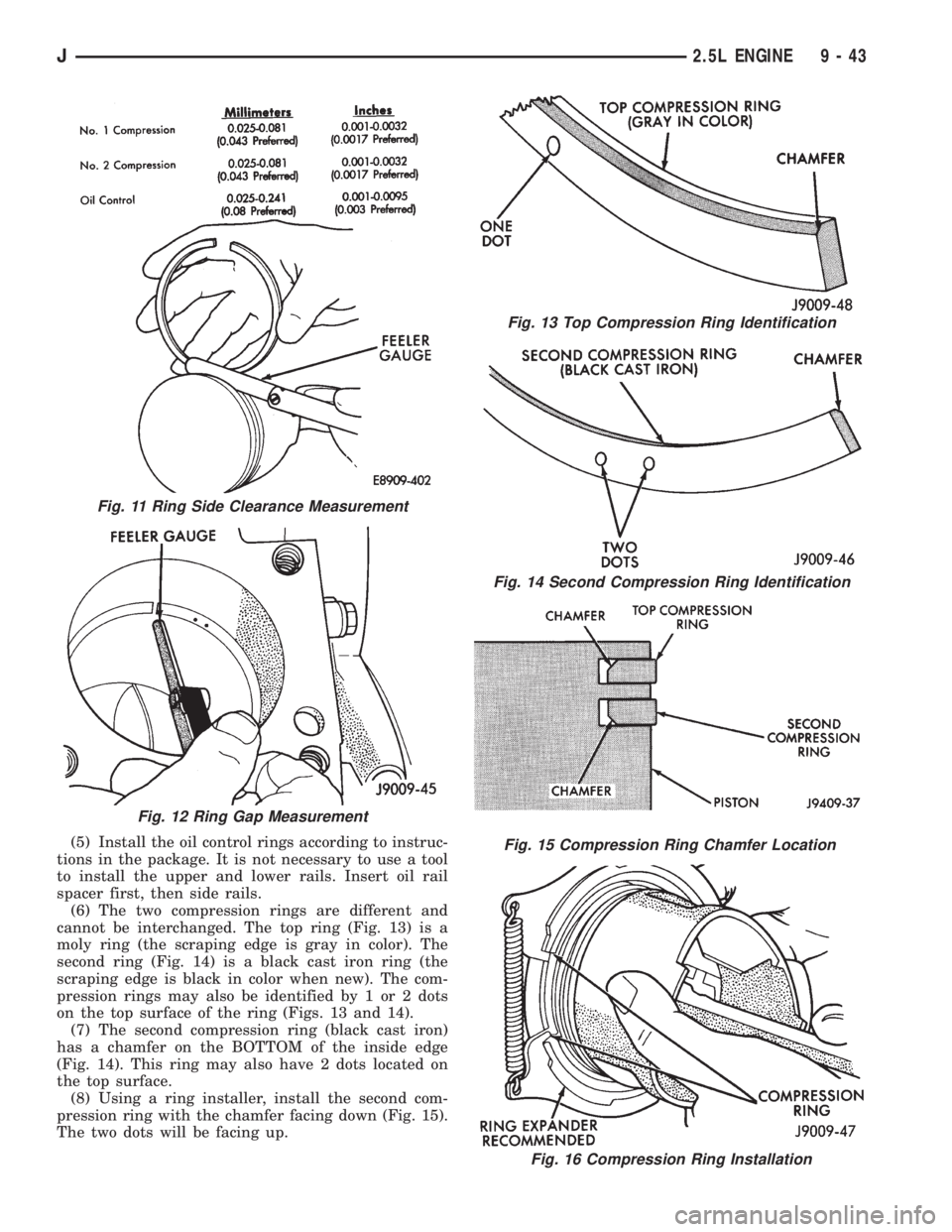
(3) Measure the ring side clearance with a feeler
gauge fitted snugly between the ring land and ring
(Fig. 10). Rotate the ring in the groove. It must move
freely around circumference of the groove.
(4) Place ring in the cylinder bore and push down
with inverted piston to position near lower end of the
ring travel. Measure ring gap with a feeler gauge fit-
ting snugly between ring ends (Fig. 12). The correct
compression ring end gap is 0.25-0.51 mm (0.010-
0.020 inch). The correct oil control ring end gap is
0.381-1.397 mm (0.015-0.055 inch).
Fig. 8 Bore Gauge
Fig. 9 Piston Size Chart
Fig. 10 Piston Dimensions
9 - 42 2.5L ENGINEJ
Page 1134 of 2198
(5) Install the oil control rings according to instruc-
tions in the package. It is not necessary to use a tool
to install the upper and lower rails. Insert oil rail
spacer first, then side rails.
(6) The two compression rings are different and
cannot be interchanged. The top ring (Fig. 13) is a
moly ring (the scraping edge is gray in color). The
second ring (Fig. 14) is a black cast iron ring (the
scraping edge is black in color when new). The com-
pression rings may also be identified by 1 or 2 dots
on the top surface of the ring (Figs. 13 and 14).
(7) The second compression ring (black cast iron)
has a chamfer on the BOTTOM of the inside edge
(Fig. 14). This ring may also have 2 dots located on
the top surface.
(8) Using a ring installer, install the second com-
pression ring with the chamfer facing down (Fig. 15).
The two dots will be facing up.
Fig. 16 Compression Ring Installation
Fig. 13 Top Compression Ring Identification
Fig. 14 Second Compression Ring Identification
Fig. 15 Compression Ring Chamfer Location
Fig. 11 Ring Side Clearance Measurement
Fig. 12 Ring Gap Measurement
J2.5L ENGINE 9 - 43
Page 1158 of 2198
LEAK-DOWN TEST
After cleaning and inspection, test each tappet for
specified leak-down rate tolerance to ensure zero-lash
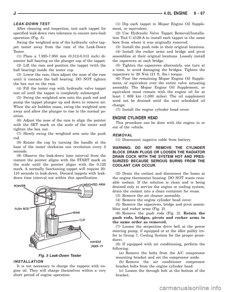
operation (Fig. 5).
Swing the weighted arm of the hydraulic valve tap-
pet tester away from the ram of the Leak-Down
Tester.
(1) Place a 7.925-7.950 mm (0.312-0.313 inch) di-
ameter ball bearing on the plunger cap of the tappet.
(2) Lift the ram and position the tappet (with the
ball bearing) inside the tester cup.
(3) Lower the ram, then adjust the nose of the ram
until it contacts the ball bearing. DO NOT tighten
the hex nut on the ram.
(4) Fill the tester cup with hydraulic valve tappet
test oil until the tappet is completely submerged.
(5) Swing the weighted arm onto the push rod and
pump the tappet plunger up and down to remove air.
When the air bubbles cease, swing the weighted arm
away and allow the plunger to rise to the normal po-
sition.
(6) Adjust the nose of the ram to align the pointer
with the SET mark on the scale of the tester and
tighten the hex nut.
(7) Slowly swing the weighted arm onto the push
rod.
(8) Rotate the cup by turning the handle at the
base of the tester clockwise one revolution every 2
seconds.
(9) Observe the leak-down time interval from the
instant the pointer aligns with the START mark on
the scale until the pointer aligns with the 0.125
mark. A normally functioning tappet will require 20-
110 seconds to leak-down. Discard tappets with leak-
down time interval not within this specification.
INSTALLATION
It is not necessary to charge the tappets with en-
gine oil. They will charge themselves within a very
short period of engine operation.(1) Dip each tappet in Mopar Engine Oil Supple-
ment, or equivalent.
(2) Use Hydraulic Valve Tappet Removal/Installa-
tion Tool C-4129-A to install each tappet in the same
bore from where it was originally removed.
(3) Install the push rods in their original locations.
(4) Install the rocker arms and bridge and pivot
assemblies at their original locations. Loosely install
the capscrews at each bridge.
(5) Tighten the capscrews alternately, one turn at
a time, to avoid damaging the bridges. Tighten the
capscrews to 28 Nzm (21 ft. lbs.) torque.
(6) Pour the remaining Mopar Engine Oil Supple-
ment, or equivalent over the entire valve actuating
assembly. The Mopar Engine Oil Supplement, or
equivalent must remain with the engine oil for at
least 1 609 km (1,000 miles). The oil supplement
need not be drained until the next scheduled oil
change.
(7) Install the engine cylinder head cover.
ENGINE CYLINDER HEAD
This procedure can be done with the engine in or
out of the vehicle.
REMOVAL
(1) Disconnect negative cable from battery.
WARNING: DO NOT REMOVE THE CYLINDER
BLOCK DRAIN PLUGS OR LOOSEN THE RADIATOR
DRAIN COCK WITH THE SYSTEM HOT AND PRES-
SURIZED BECAUSE SERIOUS BURNS FROM THE
COOLANT CAN OCCUR.
(2) Drain the coolant and disconnect the hoses at
the engine thermostat housing. DO NOT waste reus-
able coolant. If the solution is clean and is being
drained only to service the engine or cooling system,
drain the coolant into a clean container for reuse.
(3) Remove the air cleaner assembly.
(4) Remove the engine cylinder head cover.
(5) Remove the capscrews, bridge and pivot assem-
blies and rocker arms (Fig. 2).
(6) Remove the push rods (Fig. 2).Retain the
push rods, bridges, pivots and rocker arms in
the same order as removed.
(7) Loosen the serpentine drive belt at the power
steering pump, if equipped or at the idler pulley (re-
fer to Group 7, Cooling System for the proper proce-
dure).
(8) If equipped with air conditioning, perform the
following:
(a) Remove the bolts from the A/C compressor
mounting bracket and set the compressor aside.
(b) Remove the air conditioner compressor
bracket bolts from the engine cylinder head.
(c) Loosen the through bolt at the bottom of the
bracket.
Fig. 5 Leak-Down Tester
J4.0L ENGINE 9 - 67
Page 1166 of 2198
INSPECTION
Inspect the cam lobes for wear.
Inspect the bearing journals for uneven wear pat-
tern or finish.
Inspect the bearings for wear.
Inspect the distributor drive gear for wear.
If the camshaft appears to have been rubbing
against the timing case cover, examine the oil pres-
sure relief holes in the rear cam journal. The oil
pressure relief holes must be free of debris.
INSTALLATION
(1) Lubricate the camshaft with Mopar Engine Oil
Supplement, or equivalent.
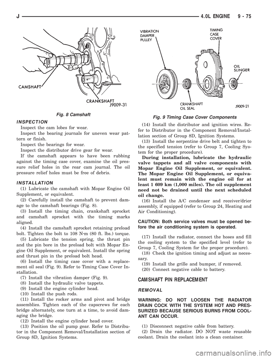
(2) Carefully install the camshaft to prevent dam-
age to the camshaft bearings (Fig. 8).
(3) Install the timing chain, crankshaft sprocket
and camshaft sprocket with the timing marks
aligned.
(4) Install the camshaft sprocket retaining preload
bolt. Tighten the bolt to 108 Nzm (80 ft. lbs.) torque.
(5) Lubricate the tension spring, the thrust pin
and the pin bore in the preload bolt with Mopar En-
gine Oil Supplement, or equivalent. Install the spring
and thrust pin in the preload bolt head.
(6) Install the timing case cover with a replace-
ment oil seal (Fig. 9). Refer to Timing Case Cover In-
stallation.
(7) Install the vibration damper (Fig. 9).
(8) Install the hydraulic valve tappets.
(9) Install the engine cylinder head.
(10) Install the push rods.
(11) Install the rocker arms and pivot and bridge
assemblies. Tighten each of the capscrews for each
bridge alternately, one turn at a time, to avoid dam-
aging the bridge.
(12) Install the engine cylinder head cover.
(13) Position the oil pump gear. Refer to Distribu-
tor in the Component Removal/Installation section of
Group 8D, Ignition Systems.(14) Install the distributor and ignition wires. Re-
fer to Distributor in the Component Removal/Instal-
lation section of Group 8D, Ignition Systems.
(13) Install the serpentine drive belt and tighten to
the specified tension (refer to Group 7, Cooling Sys-
tem for the proper procedure).
During installation, lubricate the hydraulic
valve tappets and all valve components with
Mopar Engine Oil Supplement, or equivalent.
The Mopar Engine Oil Supplement, or equiva-
lent must remain with the engine oil for at
least 1 609 km (1,000 miles). The oil supplement
need not be drained until the next scheduled
oil change.
(16) Install the A/C condenser and receiver/drier
assembly, if equipped (refer to Group 24, Heating and
Air Conditioning).
CAUTION: Both service valves must be opened be-
fore the air conditioning system is operated.
(17) Install the radiator, connect the hoses and fill
the cooling system to the specified level (refer to
Group 7, Cooling System for the proper procedure).
(18) Check the ignition timing and adjust as neces-
sary.
(19) Install the grille and bumper, if removed.
(20) Connect negative cable to battery.
CAMSHAFT PIN REPLACEMENT
REMOVAL
WARNING: DO NOT LOOSEN THE RADIATOR
DRAIN COCK WITH THE SYSTEM HOT AND PRES-
SURIZED BECAUSE SERIOUS BURNS FROM COOL-
ANT CAN OCCUR.
(1) Disconnect negative cable from battery.
(2) Drain the radiator. DO NOT waste reusable
coolant. Drain the coolant into a clean container.
Fig. 9 Timing Case Cover ComponentsFig. 8 Camshaft
J4.0L ENGINE 9 - 75