1995 JEEP CHEROKEE automatic transmission
[x] Cancel search: automatic transmissionPage 299 of 2198
CAUTION: Be certain that battery cables are con-
nected to the correct battery terminals. Reverse po-
larity can damage electrical components.
(12) Place oiled felt washer on battery positive ter-
minal post.
(13) Install and tighten battery positive cable ter-
minal clamp. Then install and tighten negative cableterminal clamp. Both cable clamp bolts require
torque of 8.5 Nzm (75 in. lbs.).
(14) Apply a thin coating of petroleum jelly or
chassis grease to cable terminals and battery posts.
STARTER AND STARTER RELAY
GENERAL INFORMATION
This section covers starter and starter relay service
procedures only. For diagnostic procedures, refer to
Group 8A - Battery/Starting/Charging Systems Diag-
nostics. Service procedures for other starting system
components can be found as follows:
²battery - see Battery, in this group
²ignition switch - refer to Group 8D - Ignition Sys-
tems
²park/neutral position switch (automatic transmis-
sion) - refer to Group 21 - Transmission and Transfer
Case
²wiring harness and connectors - refer to Group 8W
- Wiring Diagrams.
STARTER
The starter motor incorporates several features to
create a reliable, efficient, compact and lightweight
unit. A planetary gear system (intermediate trans-
mission) is used between the electric motor and pin-
ion gear. This feature makes it possible to reduce the
dimensions of the starter. At the same time, it allows
higher armature rotational speed and delivers in-
creased torque through the pinion gear to the fly-
wheel or drive plate ring gear.
The use of a permanent magnet field also reduces
starter size and weight. This field consists of six
high-strength permanent magnets. The magnets are
aligned according to their polarity and are perma-
nently fixed in the starter field frame.
The starter motors for all engines are activated by
a solenoid mounted to the overrunning clutch hous-
ing. However, the starter motor/solenoid are serviced
only as a complete assembly. If either component
fails, the entire assembly must be replaced.
This unit is highly sensitive to hammering, shocks
and external pressure.
CAUTION: The starter motor MUST NOT BE
CLAMPED in a vise by the starter field frame. Doing
so may damage the magnets. It may be clamped by
the mounting flange ONLY.CAUTION: Do not connect starter motor incorrectly
when tests are being performed. The permanent
magnets may be damaged and rendered unservice-
able.
STARTER RELAY
The starter relay is an International Standards Or-
ganization (ISO) type relay, and is located in the
Power Distribution Center (PDC). Refer to underside
of PDC cover for relay location.
STARTER REMOVE/INSTALLÐ2.5L
XJ MODELS
(1) Disconnect battery negative cable.
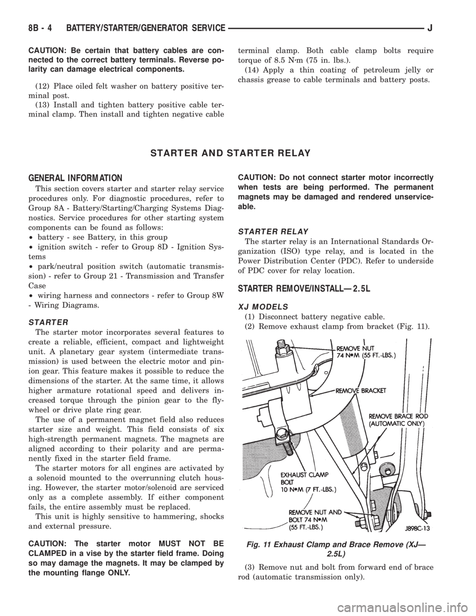
(2) Remove exhaust clamp from bracket (Fig. 11).
(3) Remove nut and bolt from forward end of brace
rod (automatic transmission only).
Fig. 11 Exhaust Clamp and Brace Remove (XJÐ
2.5L)
8B - 4 BATTERY/STARTER/GENERATOR SERVICEJ
Page 300 of 2198
(4) Remove nut from lower end of brace rod (auto-
matic transmission only).
(5) Remove brace rod and bracket (automatic
transmission only).
(6) Remove nut, bolt and bracket from bell housing
(manual transmission only).
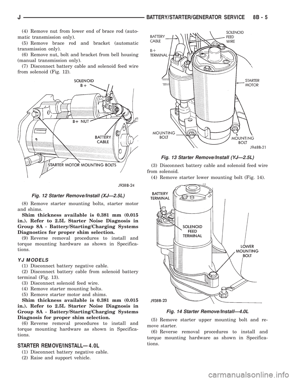
(7) Disconnect battery cable and solenoid feed wire
from solenoid (Fig. 12).
(8) Remove starter mounting bolts, starter motor
and shims.
Shim thickness available is 0.381 mm (0.015
in.). Refer to 2.5L Starter Noise Diagnosis in
Group 8A - Battery/Starting/Charging Systems
Diagnostics for proper shim selection.
(9) Reverse removal procedures to install and
torque mounting hardware as shown in Specifica-
tions.
YJ MODELS
(1) Disconnect battery negative cable.
(2) Disconnect battery cable from solenoid battery
terminal (Fig. 13).
(3) Disconnect solenoid feed wire.
(4) Remove starter mounting bolts.
(5) Remove starter motor and shims.
Shim thickness available is 0.381 mm (0.015
in.). Refer to 2.5L Starter Noise Diagnosis in
Group 8A - Battery/Starting/Charging Systems
Diagnosis for proper shim selection.
(6) Reverse removal procedures to install and
torque mounting hardware as shown in Specifica-
tions.
STARTER REMOVE/INSTALLÐ4.0L
(1) Disconnect battery negative cable.
(2) Raise and support vehicle.(3) Disconnect battery cable and solenoid feed wire
from solenoid.
(4) Remove starter lower mounting bolt (Fig. 14).
(5) Remove starter upper mounting bolt and re-
move starter.
(6) Reverse removal procedures to install and
torque mounting hardware as shown in Specifica-
tions.
Fig. 12 Starter Remove/Install (XJÐ2.5L)
Fig. 13 Starter Remove/Install (YJÐ2.5L)
Fig. 14 Starter Remove/InstallÐ4.0L
JBATTERY/STARTER/GENERATOR SERVICE 8B - 5
Page 314 of 2198
CRANKSHAFT POSITION SENSOR
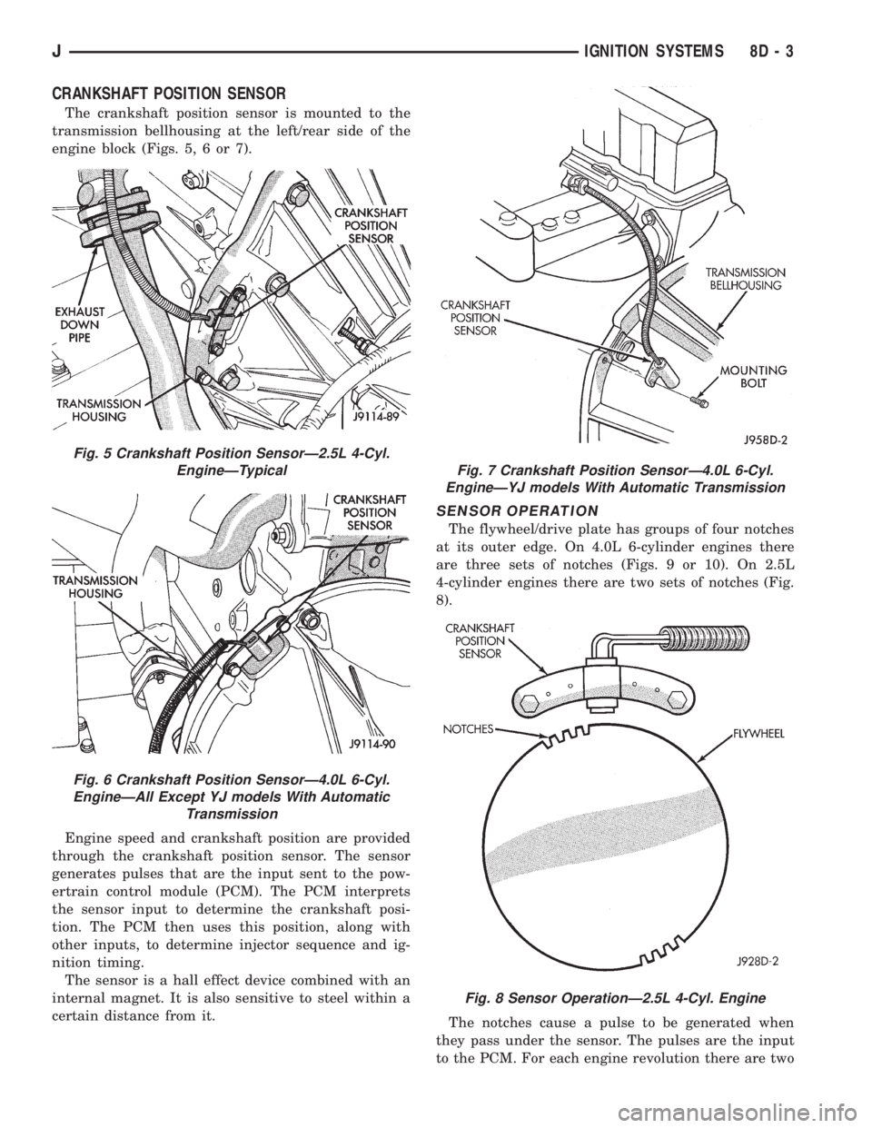
The crankshaft position sensor is mounted to the
transmission bellhousing at the left/rear side of the
engine block (Figs. 5, 6 or 7).
Engine speed and crankshaft position are provided
through the crankshaft position sensor. The sensor
generates pulses that are the input sent to the pow-
ertrain control module (PCM). The PCM interprets
the sensor input to determine the crankshaft posi-
tion. The PCM then uses this position, along with
other inputs, to determine injector sequence and ig-
nition timing.
The sensor is a hall effect device combined with an
internal magnet. It is also sensitive to steel within a
certain distance from it.
SENSOR OPERATION
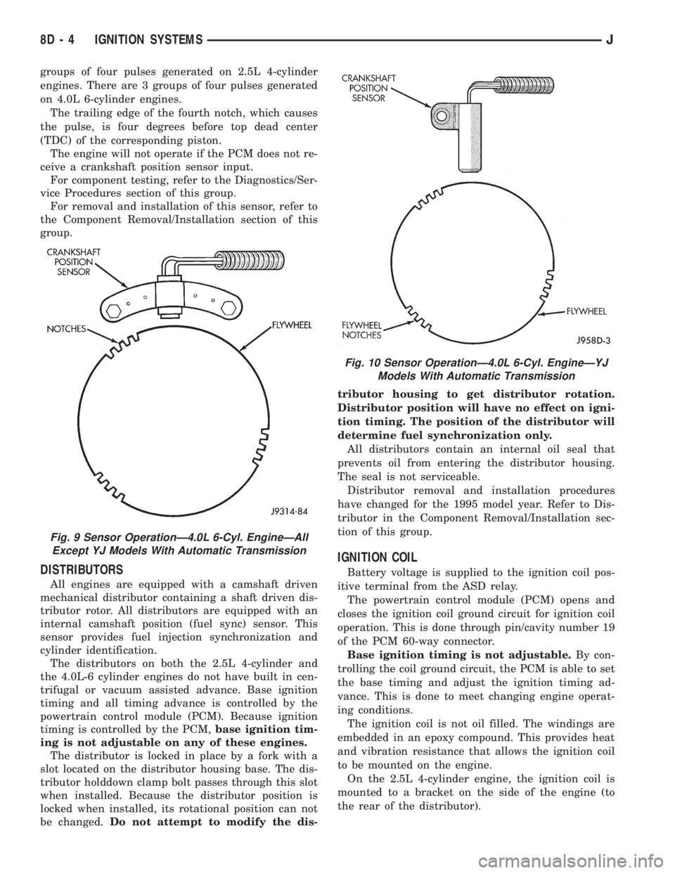
The flywheel/drive plate has groups of four notches
at its outer edge. On 4.0L 6-cylinder engines there
are three sets of notches (Figs. 9 or 10). On 2.5L
4-cylinder engines there are two sets of notches (Fig.
8).
The notches cause a pulse to be generated when
they pass under the sensor. The pulses are the input
to the PCM. For each engine revolution there are two
Fig. 5 Crankshaft Position SensorÐ2.5L 4-Cyl.
EngineÐTypical
Fig. 6 Crankshaft Position SensorÐ4.0L 6-Cyl.
EngineÐAll Except YJ models With Automatic
Transmission
Fig. 7 Crankshaft Position SensorÐ4.0L 6-Cyl.
EngineÐYJ models With Automatic Transmission
Fig. 8 Sensor OperationÐ2.5L 4-Cyl. Engine
JIGNITION SYSTEMS 8D - 3
Page 315 of 2198
groups of four pulses generated on 2.5L 4-cylinder
engines. There are 3 groups of four pulses generated
on 4.0L 6-cylinder engines.
The trailing edge of the fourth notch, which causes
the pulse, is four degrees before top dead center
(TDC) of the corresponding piston.
The engine will not operate if the PCM does not re-
ceive a crankshaft position sensor input.
For component testing, refer to the Diagnostics/Ser-
vice Procedures section of this group.
For removal and installation of this sensor, refer to
the Component Removal/Installation section of this
group.
DISTRIBUTORS
All engines are equipped with a camshaft driven
mechanical distributor containing a shaft driven dis-
tributor rotor. All distributors are equipped with an
internal camshaft position (fuel sync) sensor. This
sensor provides fuel injection synchronization and
cylinder identification.
The distributors on both the 2.5L 4-cylinder and
the 4.0L-6 cylinder engines do not have built in cen-
trifugal or vacuum assisted advance. Base ignition
timing and all timing advance is controlled by the
powertrain control module (PCM). Because ignition
timing is controlled by the PCM,base ignition tim-
ing is not adjustable on any of these engines.
The distributor is locked in place by a fork with a
slot located on the distributor housing base. The dis-
tributor holddown clamp bolt passes through this slot
when installed. Because the distributor position is
locked when installed, its rotational position can not
be changed.Do not attempt to modify the dis-tributor housing to get distributor rotation.
Distributor position will have no effect on igni-
tion timing. The position of the distributor will
determine fuel synchronization only.
All distributors contain an internal oil seal that
prevents oil from entering the distributor housing.
The seal is not serviceable.
Distributor removal and installation procedures
have changed for the 1995 model year. Refer to Dis-
tributor in the Component Removal/Installation sec-
tion of this group.
IGNITION COIL
Battery voltage is supplied to the ignition coil pos-
itive terminal from the ASD relay.
The powertrain control module (PCM) opens and
closes the ignition coil ground circuit for ignition coil
operation. This is done through pin/cavity number 19
of the PCM 60-way connector.
Base ignition timing is not adjustable.By con-
trolling the coil ground circuit, the PCM is able to set
the base timing and adjust the ignition timing ad-
vance. This is done to meet changing engine operat-
ing conditions.
The ignition coil is not oil filled. The windings are
embedded in an epoxy compound. This provides heat
and vibration resistance that allows the ignition coil
to be mounted on the engine.
On the 2.5L 4-cylinder engine, the ignition coil is
mounted to a bracket on the side of the engine (to
the rear of the distributor).
Fig. 9 Sensor OperationÐ4.0L 6-Cyl. EngineÐAll
Except YJ Models With Automatic Transmission
Fig. 10 Sensor OperationÐ4.0L 6-Cyl. EngineÐYJ
Models With Automatic Transmission
8D - 4 IGNITION SYSTEMSJ
Page 329 of 2198
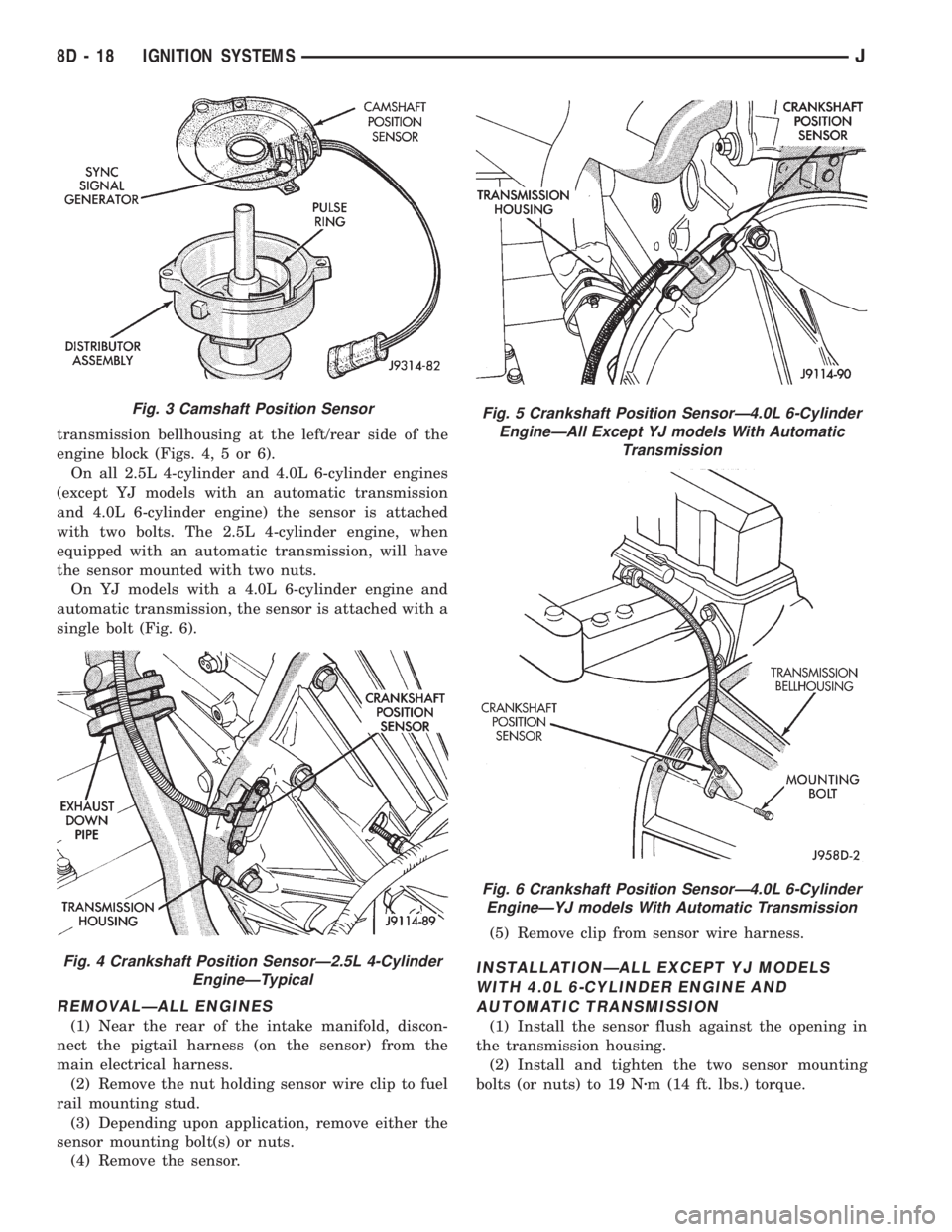
transmission bellhousing at the left/rear side of the
engine block (Figs. 4, 5 or 6).
On all 2.5L 4-cylinder and 4.0L 6-cylinder engines
(except YJ models with an automatic transmission
and 4.0L 6-cylinder engine) the sensor is attached
with two bolts. The 2.5L 4-cylinder engine, when
equipped with an automatic transmission, will have
the sensor mounted with two nuts.
On YJ models with a 4.0L 6-cylinder engine and
automatic transmission, the sensor is attached with a
single bolt (Fig. 6).
REMOVALÐALL ENGINES
(1) Near the rear of the intake manifold, discon-
nect the pigtail harness (on the sensor) from the
main electrical harness.
(2) Remove the nut holding sensor wire clip to fuel
rail mounting stud.
(3) Depending upon application, remove either the
sensor mounting bolt(s) or nuts.
(4) Remove the sensor.(5) Remove clip from sensor wire harness.
INSTALLATIONÐALL EXCEPT YJ MODELS
WITH 4.0L 6-CYLINDER ENGINE AND
AUTOMATIC TRANSMISSION
(1) Install the sensor flush against the opening in
the transmission housing.
(2) Install and tighten the two sensor mounting
bolts (or nuts) to 19 Nzm (14 ft. lbs.) torque.
Fig. 3 Camshaft Position Sensor
Fig. 4 Crankshaft Position SensorÐ2.5L 4-Cylinder
EngineÐTypical
Fig. 5 Crankshaft Position SensorÐ4.0L 6-Cylinder
EngineÐAll Except YJ models With Automatic
Transmission
Fig. 6 Crankshaft Position SensorÐ4.0L 6-Cylinder
EngineÐYJ models With Automatic Transmission
8D - 18 IGNITION SYSTEMSJ
Page 330 of 2198
CAUTION: On some models, two bolts are used to
secure the sensor to the transmission. These bolts
are specially machined to correctly space the unit
to the flywheel. Do not attempt to install any other
bolts.
(3) Connect the electrical connector to the sensor.
(4) Install clip on sensor wire harness.
(5) Install clip over fuel rail mounting stud. Install
clip mounting nut.
INSTALLATIONÐYJ MODELS WITH 4.0L
6-CYLINDER ENGINE AND AUTOMATIC
TRANSMISSION
(1) Install the sensor into the access hole on the
transmission.
(2) Install sensor mounting bolt (Fig. 6).
(3) Tighten sensor mounting bolt to 6-to-8 Nzm (50-
to-70 in. lbs.) torque.
(4) Connect the electrical connector to sensor.
(5) Install the clip to sensor wire harness.
(6) Install clip over fuel rail mounting stud. Install
clip mounting nut.
ENGINE COOLANT TEMPERATURE SENSOR
For an operational description, diagnosis and re-
moval/installation procedures, refer to Group 14,
Fuel System.
DISTRIBUTOR
GENERAL INFORMATION
All distributors contain an internal oil seal that
prevents oil from entering the distributor housing.
The seal is not serviceable.
Factory replacement distributors are equipped with
a plastic alignment pin already installed. The pin is
located in an access hole on the bottom of the distrib-
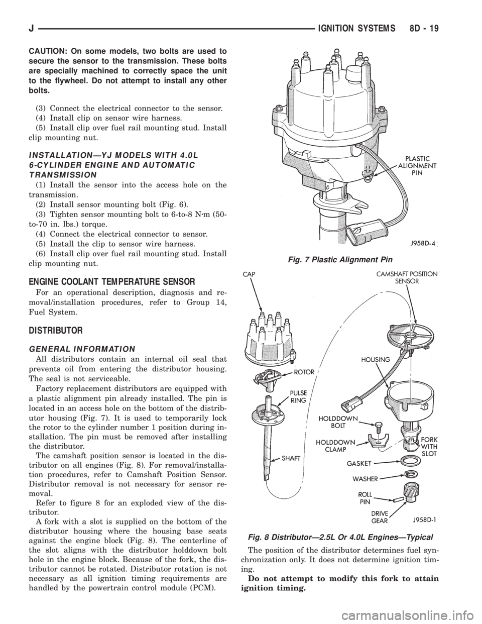
utor housing (Fig. 7). It is used to temporarily lock
the rotor to the cylinder number 1 position during in-
stallation. The pin must be removed after installing
the distributor.
The camshaft position sensor is located in the dis-
tributor on all engines (Fig. 8). For removal/installa-
tion procedures, refer to Camshaft Position Sensor.
Distributor removal is not necessary for sensor re-
moval.
Refer to figure 8 for an exploded view of the dis-
tributor.
A fork with a slot is supplied on the bottom of the
distributor housing where the housing base seats
against the engine block (Fig. 8). The centerline of
the slot aligns with the distributor holddown bolt
hole in the engine block. Because of the fork, the dis-
tributor cannot be rotated. Distributor rotation is not
necessary as all ignition timing requirements are
handled by the powertrain control module (PCM).The position of the distributor determines fuel syn-
chronization only. It does not determine ignition tim-
ing.
Do not attempt to modify this fork to attain
ignition timing.
Fig. 7 Plastic Alignment Pin
Fig. 8 DistributorÐ2.5L Or 4.0L EnginesÐTypical
JIGNITION SYSTEMS 8D - 19
Page 423 of 2198
The two pivot cranks are joined by a connecting link,
and a drive link connects the motor crank to the drive
link near the left pivot. Pressed-in plastic bushings in
the ends of the links can be replaced if worn or dam-
aged.
WINDSHIELD WIPER MOTOR
The two-speed permanent magnet wiper motor has
an integral transmission and park switch. The motor
is mounted to the engine side of the cowl panel with
a reinforcement/stud plate and a rubber-isolated
mounting bracket. The wiper motor output shaft
passes through the cowl panel into the cowl plenum
area, where a crank arm attached to the output shaft
drives the wiper drive link.
Wiper speed is controlled by current flow to the ap-
propriate set of brushes. The wiper motor completes
its wipe cycle when the switch is turned OFF, and
parks the blades in the lowest portion of the wipe
pattern. The wiper motor assembly can not be re-
paired. If faulty, the entire motor assembly must be
replaced. The crank arm, mounting bracket, and re-
inforcement/stud plate are available for service.
LIFTGATE WIPER MOTOR
The liftgate wiper motor contains integral elec-
tronic controls and a transmission to provide three
operating modes:
²intermittent wipe with a fixed 5 to 8 second delay
between wipes
²constant wipe that operates when the liftgate
washer is operated
²a park mode that runs the motor until the wiper
blade reaches the park position after the liftgate
wiper switch or ignition switch is turned OFF.
The liftgate wiper motor can not be repaired. If
faulty, the entire assembly must be replaced.
WINDSHIELD WIPER/WASHER SWITCH
Controls for the windshield wiper and washer sys-
tems are contained in the multi-function switch con-
trol lever. The multi-function switch is mounted on
the left side of the steering column between the
steering wheel and the instrument panel. This switch
also controls many other functions. The multi-func-
tion switch can not be repaired. If any function of the
switch is faulty, the entire switch must be replaced.
LIFTGATE WIPER/WASHER SWITCH
The single two-function switch on the instrument
panel right of the steering column controls the lift-
gate wiper and washer functions. The rocker-type
switch features a detent in the WIPE position, but
only momentary contact in the WASH position. Both
the liftgate wiper and liftgate washer motors will op-
erate continuously for as long as the switch is held in
the WASH position. The switch can not be repaired;
if faulty, it must be replaced.
INTERMITTENT WIPE MODULE
In addition to low and high speed, the optional inter-
mittent wipe system has a delay mode. The delay mode
has a range of 2 to 15 seconds. The length of the delay
is selected with a variable resistor in the wiper (multi-
function) switch and is accomplished by electronic cir-
cuitry within the intermittent wipe module. If the
washer knob is depressed while the wiper (multi-func-
tion) switch is in the OFF position, the intermittent
wipe module will operate the wiper motor for approxi-
mately 2 wipes and automatically turn the motor off.
The intermittent wipe module is mounted to the
lower instrument panel, behind the knee blocker and
near the steering column with a hook and loop fas-
tener patch. The module can not be repaired.
WINDSHIELD WASHER NOZZLES
The two fluidic washer nozzles are riveted into
openings in the cowl grille panel below the wind-
shield and are not adjustable. Washer fluid is fed to
the nozzles through hoses clipped to the underside of
the cowl grille panel. The nozzles can not be repaired
and, if faulty, should be replaced.
LIFTGATE WASHER NOZZLE
The single liftgate washer nozzle snaps into place
on the liftgate wiper arm. Washer fluid is fed to the
nozzle from the washer reservoir in the engine com-
partment. A liftgate washer hose system is routed
through the body of the vehicle with the body wiring
harness from the reservoir to the liftgate. The fluid
passes through a nipple on the liftgate wiper motor
output shaft bezel to a hose clipped to the underside
of the wiper arm. The nozzle can not be repaired and,
if faulty, should be replaced.
WASHER RESERVOIR
The washer solvent reservoir is mounted to the left
front inner fender shield near the cowl panel. The
same reservoir is used for both the standard front
and optional liftgate washer systems. It also has a
provision for a low washer fluid level sensor. Refer to
Group 8E - Instrument Panel and Gauges for diagno-
sis and service of the sensor. The reservoir and filler
cap are available for service.
WASHER PUMPS
The washer pump and motor are press-fit into a
rubber grommet near the bottom of the washer res-
ervoir. Vehicles with the optional liftgate wiper/
washer system have two pumps installed in the
single reservoir. A permanently lubricated and sealed
motor is coupled to a rotor-type pump. Washer fluid
is gravity fed from the reservoir to the pump. The
pump then pressurizes the fluid and forces it through
the plumbing to the nozzles when the motor is ener-
gized. The pump and motor can not be repaired. If
faulty, the entire assembly must be replaced.
8K - 2 WIPER AND WASHER SYSTEMS - XJJ
Page 522 of 2198
WIRING DIAGRAMSÐGENERAL INFORMATION
INDEX
page page
Circuit Identification......................... 1
Connector and Terminal Replacement........... 7
Connector Replacement..................... 6
Connectors............................... 2
Diode Replacement........................ 8
Electrostatic Discharge (ESC) Sensitive Devices . . . 2
General Information......................... 1
Intermittent and Poor Connections.............. 4
Notes, Cautions, and Warnings................ 1Symbols................................. 2
Take Outs................................ 2
Terminal Replacement....................... 8
Terminal/Connector RepairÐMolex Connectors.... 6
Troubleshooting Tests....................... 4
Troubleshooting Tools....................... 4
Troubleshooting Wiring Problems.............. 5
Wire Code Identification..................... 1
Wiring Repair............................. 6
GENERAL INFORMATION
This Group is divided into three stand alone sec-
tions; XJ, YJ, and XJ Right Hand Drive (XJ-RHD).
Separate circuit descriptions and wiring diagrams are
provided for each vehicle. Each section contains a
Contents list for the wiring diagrams and circuit de-
scriptions for that vehicle.
The complete XJ circuit descriptions and diagrams
are printed first, followed by those for the YJ and
then the XJ-RHD. The heading at the top of each
page identifies the vehicle covered in the section.
NOTES, CAUTIONS, and WARNINGS
Throughout this group additional important infor-
mation is presented in three ways; Notes, Cautions,
and Warnings.
NOTESare used to help describe how switches or
components operate to complete a particular circuit.
They are also used to indicate different conditions
that may appear on the vehicle. For example, an
up-to and after condition.
CAUTIONSare used to indicate information that
could prevent making an error that may damage the
vehicle.
WARNINGSprovide information to prevent per-
sonal injury and vehicle damage. Below is a list of
general warnings that should be followed any time a
vehicle is being serviced.
ALWAYS WEAR SAFETY GLASSES FOR EYE PRO-
TECTION.
USE SAFETY STANDS ANYTIME A PROCEDURE RE-
QUIRES BEING UNDER A VEHICLE.
BE SURE THAT THE IGNITION SWITCH ALWAYS IS
IN THE OFF POSITION, UNLESS THE PROCEDURE
REQUIRES IT TO BE ON.SET THE PARKING BRAKE WHEN WORKING ON
ANY VEHICLE. AN AUTOMATIC TRANSMISSION
SHOULD BE IN PARK. A MANUAL TRANSMISSION
SHOULD BE IN NEUTRAL.
OPERATE THE ENGINE ONLY IN A WELL-VENTI-
LATED AREA.
KEEP AWAY FROM MOVING PARTS WHEN THE EN-
GINE IS RUNNING, ESPECIALLY THE FAN AND BELTS.
TO PREVENT SERIOUS BURNS, AVOID CONTACT
WITH HOT PARTS SUCH AS THE RADIATOR, EX-
HAUST MANIFOLD(S), TAIL PIPE, CATALYTIC CON-
VERTER, AND MUFFLER.
DO NOT ALLOW FLAME OR SPARKS NEAR THE
BATTERY. GASES ARE ALWAYS PRESENT IN AND
AROUND THE BATTERY.
ALWAYS REMOVE RINGS, WATCHES, LOOSE
HANGING JEWELRY, AND LOOSE CLOTHING.
WIRE CODE IDENTIFICATION
Each wire shown in the diagrams contains a code
(Fig. 1) which identifies the main circuit, part of the
main circuit, gauge of wire, and color. The color is
shown as a two letter code which can be identified by
referring to the Wire Color Code Chart (Fig. 2).
CIRCUIT IDENTIFICATION
All circuits in the diagrams use an alpha/numeric
code to identify the wire and its function (Fig. 3). To
identify which circuit code applies to a system, refer
to the Circuit Identification Code Chart. This chart
shows the main circuits only and does not show the
secondary codes that may apply to some models.
JWIRING DIAGRAMSÐGENERAL INFORMATION 8W - 1