1995 JEEP CHEROKEE ignition
[x] Cancel search: ignitionPage 1367 of 2198
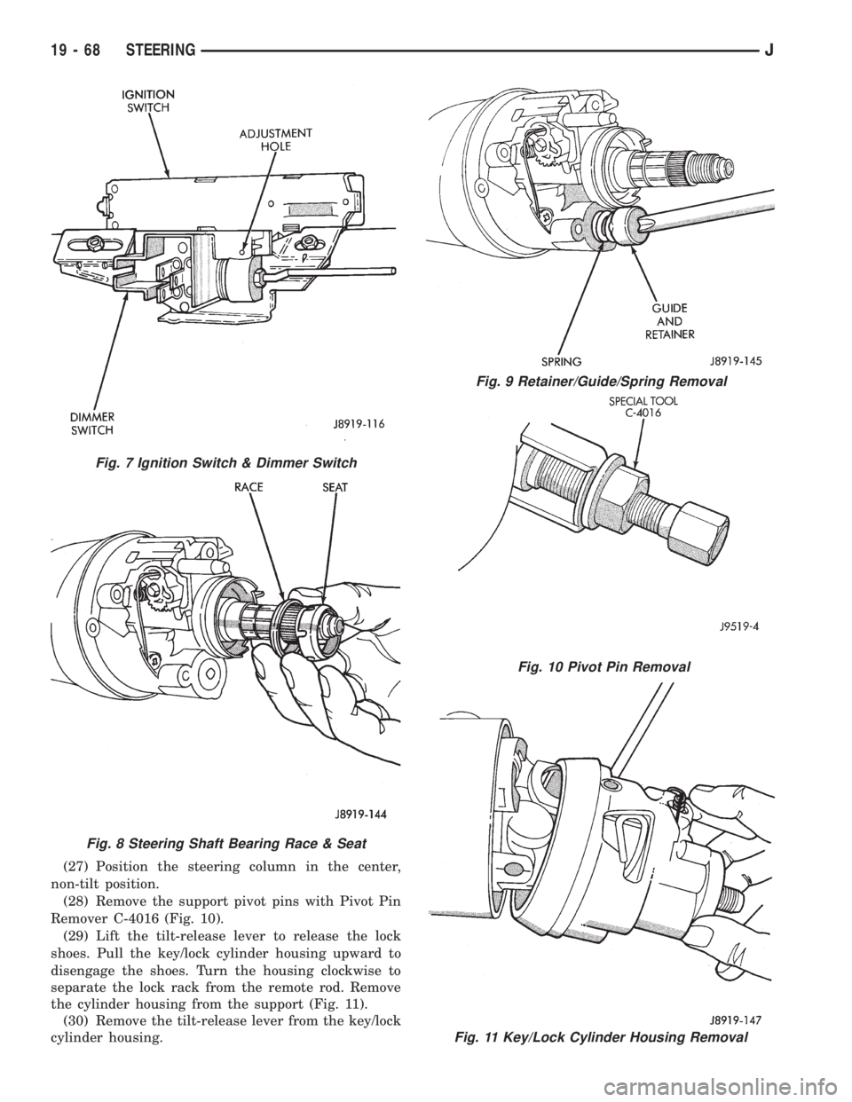
(27) Position the steering column in the center,
non-tilt position.
(28) Remove the support pivot pins with Pivot Pin
Remover C-4016 (Fig. 10).
(29) Lift the tilt-release lever to release the lock
shoes. Pull the key/lock cylinder housing upward to
disengage the shoes. Turn the housing clockwise to
separate the lock rack from the remote rod. Remove
the cylinder housing from the support (Fig. 11).
(30) Remove the tilt-release lever from the key/lock
cylinder housing.
Fig. 10 Pivot Pin Removal
Fig. 11 Key/Lock Cylinder Housing Removal
Fig. 7 Ignition Switch & Dimmer Switch
Fig. 8 Steering Shaft Bearing Race & Seat
Fig. 9 Retainer/Guide/Spring Removal
19 - 68 STEERINGJ
Page 1371 of 2198
(9) Install the shift tube thrust washer and the re-
tainer plate snap ring.
(10) Install the lower bearing in the steering col-
umn.
(11) Position the shift gate in the steering column
support. Install the attaching screws.
(12) Position the support in the steering column.
(13) Install all support attaching screws finger-
tight. Next, tighten the screws alternately and evenly
to7Nzm (60 in. lbs.) torque.
(14) Install the remote rod in the support. Route
the rod through the upper end of the shroud and in-
sert it into the rod slot located in the support.
(15) Install the dimmer switch and ignition switch.
(16) Install the steering shaft in the steering col-
umn.
(17) Install replacement races and bearings in the
key/lock cylinder, if removed.Ensure that the bear-
ings are lubricated with chassis lubricant be-
fore installation.
(18) Install the lock shoes, the lock shoe springs
and the lock shoe pin the key/lock cylinder housing.
Use a 4.5-mm (0.18-in) diameter rod to align the
shoes and the pin during installation.
(19) Install the tilt-release lever, the lever spring
and the lever pin in the key/lock cylinder housing.
Insert a wedge between the housing and the lever to
relieve the spring tension. This will allow easier re-
lease lever pin installation.
(20) Install the lock bolt in the key/lock cylinder
housing and engage it in the lock sector cam surface.
(21) Install the lock rack, the rack preload spring
and a replacement shim in the key/lock cylinder
housing. Align and mate the square block tooth on
the lock rack and the lock sector.
(22) Install the lock spring and the spring retain-
ing screw. Tighten the screw to 4 Nzm (35 in. lbs.)
torque.
(23) Align and install the assembled key/lock cylin-
der housing on the support. Retain the lock shoes in
the disengaged position for easier housing installa-
tion.
(24) Align the pivot pin holes in the housing with
those in the support. Insert the pivot pins.Press the
housing firmly downward when inserting the
pivot pins. This prevents damaging the holes in
the support.When the pivot pins are within both
the housing and the support holes, seat them fully
with a punch and a hammer.
(25) Insert tilt-release lever in key/lock cylinder
housing and place housing in the full-upward tilt po-
sition.
(26) Lubricate the tilt spring guide and the tilt
spring liberally with chassis lubricant and position
the spring on the guide.
(27) Insert the tilt spring guide and the spring into
the key/lock cylinder housing. Install the guide re-tainer over the spring. Engage the retainer lock tabs
with the housing lugs by pressing the retainer down-
ward and turning clockwise with a screwdriver.
(28) Place the cover on the key/lock cylinder hous-
ing. Align and install the cover retaining screws.
Tighten the screws to 7 Nzm (60 in. lbs.) torque.
(29) Install the gear selector indicator lamp mount-
ing bracket screw.
(30) Install the gear selector indicator cover and
retaining screws.
(31) Route the dimmer switch wire harness and
gear selector indicator down through the steering col-
umn.
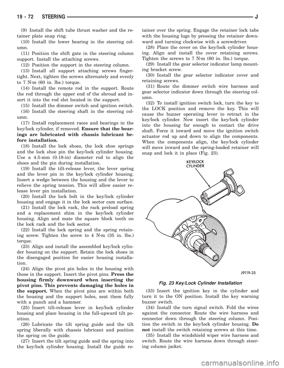
(32) To install ignition switch lock, turn the key to
the LOCK position and remove the key. This will
cause the buzzer operating lever to retract in the
key/lock cylinder. Now insert the key/lock cylinder
into the housing far enough to contact the drive
shaft. Force it inward and move the ignition switch
actuator rod up and down to align the components.
When the components align, the key/lock cylinder
will move inward and the spring-loaded retainer will
snap and lock it in place (Fig. 23).
(33) Insert the ignition key in the cylinder and
turn it to the ON position. Install the key warning
buzzer switch.
(34) Install the turn signal switch. Fold the wires
against the connector. Route the wire harness and
connector down through the steering column. Posi-
tion the switch in the key/lock cylinder housing.Do
notinstall the switch retaining screws at this time.
(35) Install the windshield wiper wire harness and
switch. Route the wire harness down through steer-
ing column jacket.
Fig. 23 Key/Lock Cylinder Installation
19 - 72 STEERINGJ
Page 1372 of 2198
(36) If equipped, install the cruise control wire har-
ness. Install the turn signal stalk by pushing it
straight into the column.
(37) Insert the hazard warning knob in the hazard
warning switch and press it inward. Align and install
the turn signal switch retaining screws. Ensure that
the turn signal switch is properly seated before tight-
ening the screws. Tighten the screws to 4 Nzm (33 in.
lbs.) torque. Thread the hazard warning switch knob
into the switch and pull the knob outward.
(38) Install and seat the upper bearing race in the
key/lock cylinder housing.
(39) Install the upper bearing preload spring, the
canceling cam and the lockplate.
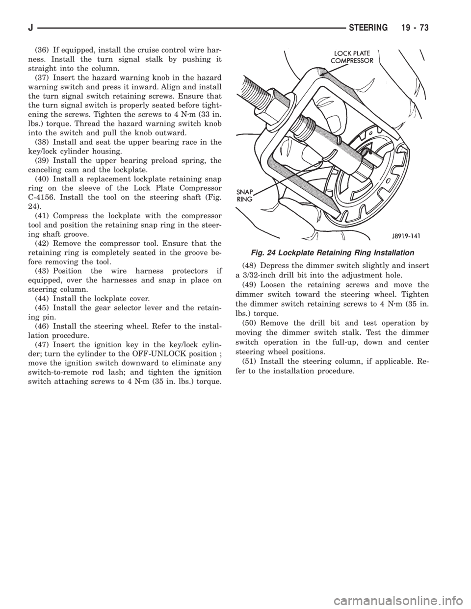
(40) Install a replacement lockplate retaining snap
ring on the sleeve of the Lock Plate Compressor
C-4156. Install the tool on the steering shaft (Fig.
24).
(41) Compress the lockplate with the compressor
tool and position the retaining snap ring in the steer-
ing shaft groove.
(42) Remove the compressor tool. Ensure that the
retaining ring is completely seated in the groove be-
fore removing the tool.
(43) Position the wire harness protectors if
equipped, over the harnesses and snap in place on
steering column.
(44) Install the lockplate cover.
(45) Install the gear selector lever and the retain-
ing pin.
(46) Install the steering wheel. Refer to the instal-
lation procedure.
(47) Insert the ignition key in the key/lock cylin-
der; turn the cylinder to the OFF-UNLOCK position ;
move the ignition switch downward to eliminate any
switch-to-remote rod lash; and tighten the ignition
switch attaching screws to 4 Nzm (35 in. lbs.) torque.(48) Depress the dimmer switch slightly and insert
a 3/32-inch drill bit into the adjustment hole.
(49) Loosen the retaining screws and move the
dimmer switch toward the steering wheel. Tighten
the dimmer switch retaining screws to 4 Nzm (35 in.
lbs.) torque.
(50) Remove the drill bit and test operation by
moving the dimmer switch stalk. Test the dimmer
switch operation in the full-up, down and center
steering wheel positions.
(51) Install the steering column, if applicable. Re-
fer to the installation procedure.
Fig. 24 Lockplate Retaining Ring Installation
JSTEERING 19 - 73
Page 1478 of 2198
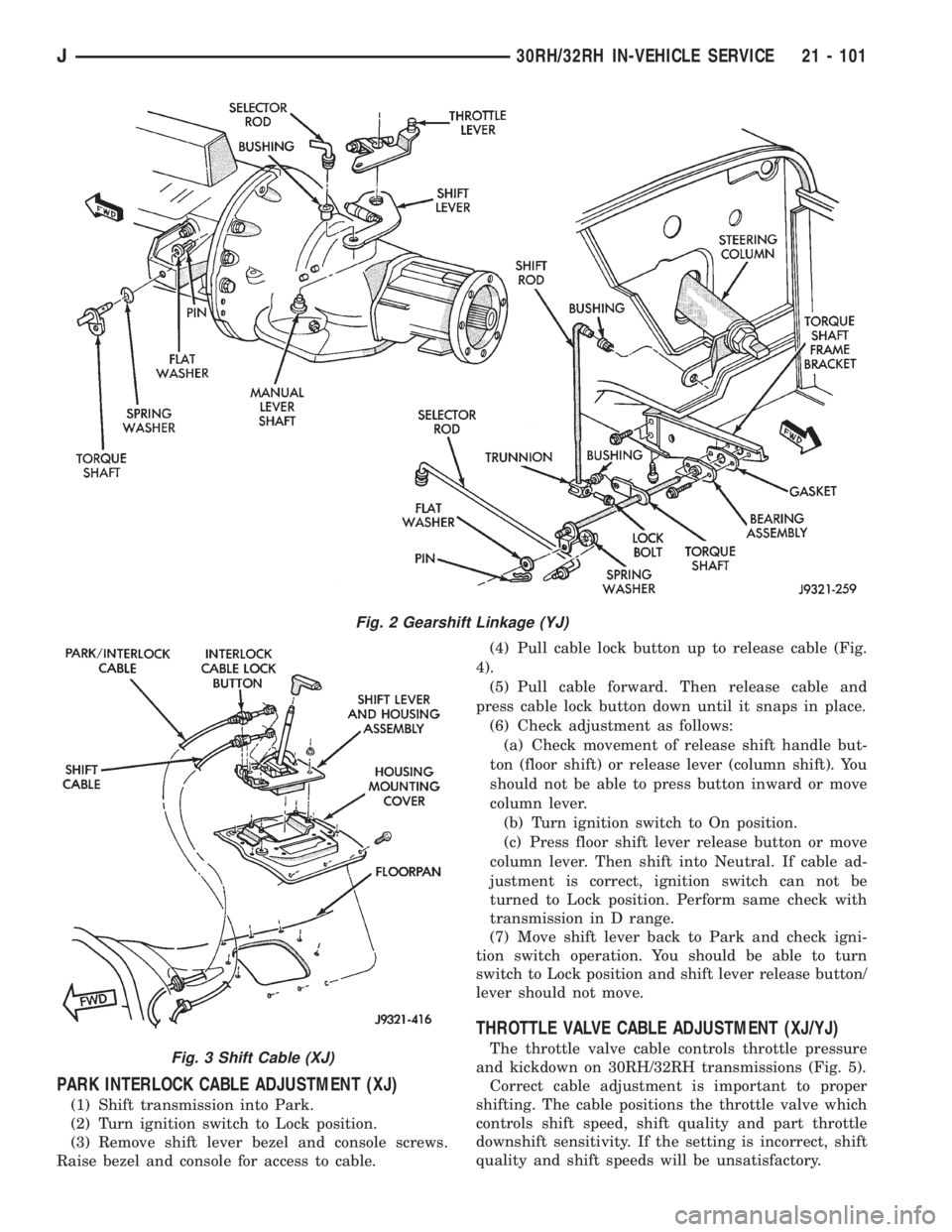
PARK INTERLOCK CABLE ADJUSTMENT (XJ)
(1) Shift transmission into Park.
(2) Turn ignition switch to Lock position.
(3) Remove shift lever bezel and console screws.
Raise bezel and console for access to cable.(4) Pull cable lock button up to release cable (Fig.
4).
(5) Pull cable forward. Then release cable and
press cable lock button down until it snaps in place.
(6) Check adjustment as follows:
(a) Check movement of release shift handle but-
ton (floor shift) or release lever (column shift). You
should not be able to press button inward or move
column lever.
(b) Turn ignition switch to On position.
(c) Press floor shift lever release button or move
column lever. Then shift into Neutral. If cable ad-
justment is correct, ignition switch can not be
turned to Lock position. Perform same check with
transmission in D range.
(7) Move shift lever back to Park and check igni-
tion switch operation. You should be able to turn
switch to Lock position and shift lever release button/
lever should not move.
THROTTLE VALVE CABLE ADJUSTMENT (XJ/YJ)
The throttle valve cable controls throttle pressure
and kickdown on 30RH/32RH transmissions (Fig. 5).
Correct cable adjustment is important to proper
shifting. The cable positions the throttle valve which
controls shift speed, shift quality and part throttle
downshift sensitivity. If the setting is incorrect, shift
quality and shift speeds will be unsatisfactory.
Fig. 2 Gearshift Linkage (YJ)
Fig. 3 Shift Cable (XJ)
J30RH/32RH IN-VEHICLE SERVICE 21 - 101
Page 1572 of 2198
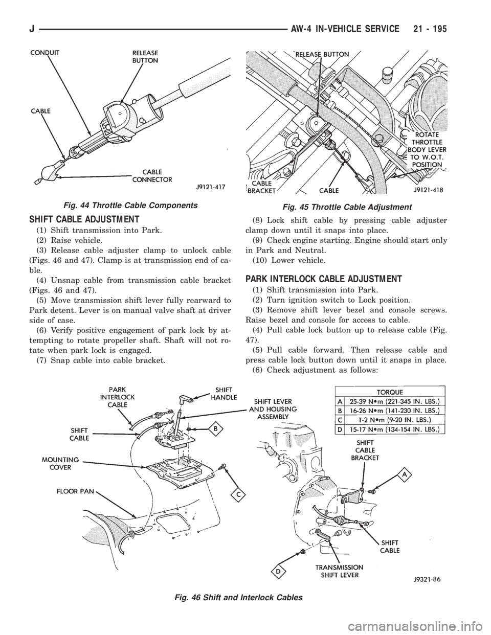
SHIFT CABLE ADJUSTMENT
(1) Shift transmission into Park.
(2) Raise vehicle.
(3) Release cable adjuster clamp to unlock cable
(Figs. 46 and 47). Clamp is at transmission end of ca-
ble.
(4) Unsnap cable from transmission cable bracket
(Figs. 46 and 47).
(5) Move transmission shift lever fully rearward to
Park detent. Lever is on manual valve shaft at driver
side of case.
(6) Verify positive engagement of park lock by at-
tempting to rotate propeller shaft. Shaft will not ro-
tate when park lock is engaged.
(7) Snap cable into cable bracket.(8) Lock shift cable by pressing cable adjuster
clamp down until it snaps into place.
(9) Check engine starting. Engine should start only
in Park and Neutral.
(10) Lower vehicle.
PARK INTERLOCK CABLE ADJUSTMENT
(1) Shift transmission into Park.
(2) Turn ignition switch to Lock position.
(3) Remove shift lever bezel and console screws.
Raise bezel and console for access to cable.
(4) Pull cable lock button up to release cable (Fig.
47).
(5) Pull cable forward. Then release cable and
press cable lock button down until it snaps in place.
(6) Check adjustment as follows:
Fig. 45 Throttle Cable Adjustment
Fig. 46 Shift and Interlock Cables
Fig. 44 Throttle Cable Components
JAW-4 IN-VEHICLE SERVICE 21 - 195
Page 1573 of 2198
(a) Check movement of release shift handle but-
ton (floor shift) or release lever (column shift). You
should not be able to press button inward or move
column lever.
(b) Turn ignition switch to On position.
(c) Press floor shift lever release button or move
column lever. Then shift into Neutral. If cable ad-
justment is correct, ignition switch can not be
turned to Lock position. Perform same check with
transmission in D range.
(7) Move shift lever back to Park and check igni-
tion switch operation. You should be able to turn
switch to Lock position and shift lever release button/
lever should not move.
TRANSMISSION COOLER SERVICE
Main Cooler
The transmission main cooler is located in the ra-
diator. The main cooler can be flushed when neces-
sary, however, the cooler is not a repairable
component. If the cooler is damaged, plugged, or
leaking, the radiator will have to be replaced.
Auxiliary Cooler
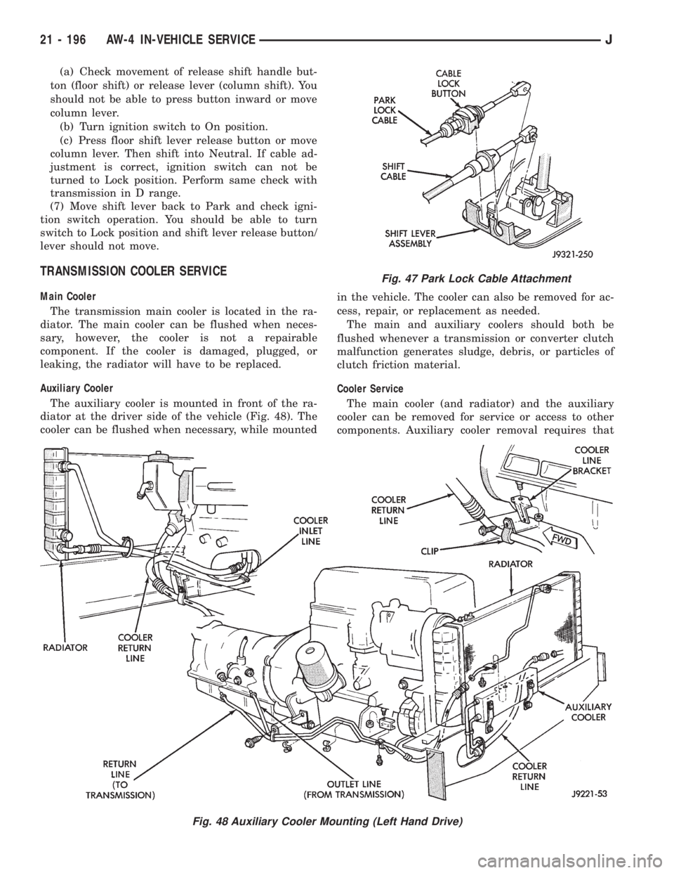
The auxiliary cooler is mounted in front of the ra-
diator at the driver side of the vehicle (Fig. 48). The
cooler can be flushed when necessary, while mountedin the vehicle. The cooler can also be removed for ac-
cess, repair, or replacement as needed.
The main and auxiliary coolers should both be
flushed whenever a transmission or converter clutch
malfunction generates sludge, debris, or particles of
clutch friction material.
Cooler Service
The main cooler (and radiator) and the auxiliary
cooler can be removed for service or access to other
components. Auxiliary cooler removal requires that
Fig. 47 Park Lock Cable Attachment
Fig. 48 Auxiliary Cooler Mounting (Left Hand Drive)
21 - 196 AW-4 IN-VEHICLE SERVICEJ
Page 1910 of 2198
HEATING AND AIR CONDITIONING TEST PROCEDURES
INDEX
page page
A/C Compressor Clutch..................... 15
A/C Compressor Clutch Relay................ 15
A/C Compressor Clutch Relay................ 16
Air Conditioning ControlsÐXJ Vehicles......... 15
Air Conditioning ControlsÐYJ Vehicles......... 16
Blower Motor............................ 17
Blower Motor Switch....................... 16Compressor Clutch........................ 16
Fin Sensing Cycling Clutch Switch............. 15
Heater Diagnosis......................... 17
Low-Pressure High-Pressure Cut-Off Switch..... 15
Low-Pressure High-Pressure Cut-Off Switch..... 16
Thermostatic Control....................... 16
AIR CONDITIONING CONTROLSÐXJ VEHICLES
The A/C Compressor Clutch is controlled by several
components: the Pressure Cut-Off Switch, Cycling
Clutch Switch, Clutch Relay and Powertrain Control
Module (PCM).
Powertrain Control Module may delay A/C clutch
engagement up to 30 seconds.
Refer to Group 8W Wiring Diagrams for wiring and
terminals. Use volt ohmmeter to test switches.
A/C COMPRESSOR CLUTCH
The clutch assembly consists of a stationary elec-
tromagnetic coil, hub bearing pulley assembly, and
clutch plate. When the coil is energized the plate is
magnetically engaged with the pulley and turns the
compressor shaft.
A/C COMPRESSOR CLUTCH TEST
(1) Unplug clutch coil connector.
(2) Connect a jumper wire from the battery posi-
tive post to the clutch coil terminal. The clutch
should engage, if not leave jumper wire connected
and go to next step.
(3) Connect a jumper wire from clutch coil frame to
chassis ground. The clutch should engage if not re-
pair clutch coil ground or replace coil.
A/C COMPRESSOR CLUTCH RELAY
The A/C compressor clutch relay controls the 12-
volt source to the A/C clutch. The relay is activated
when the PCM receives a A/C request signal from the
fin-sensed cycling clutch switch. The PCM then sends
a ground signal to the relay. The relay is activated
and sends 12-volts to the clutch coil which energizes
the clutch. The relay is located in the power distribu-
tion center.
COMPRESSOR CLUTCH RELAY TEST
For test procedure refer to Powertrain Diagnostic
Service Manual for A/C clutch relay circuit test.
LOW-PRESSURE HIGH-PRESSURE CUT-OFF
SWITCH
The pressure cut-off switch is located on the filter
drier and is wired in series with compressor clutch.
The switch interrupts the power to the compressor
clutch circuit when the pressure drops to 193 kPa (28
psi) or increases above 3100 to 3375 kPa (450 to 490
psi).
PRESSURE CUT-OFF SWITCH TEST
(1) Verify system has correct refrigerant charge.
(2) Turn ignition switch to RUN, A/C blower switch
to ON and control set to MAX.
(3) Unplug pressure cut-off switch and test feed
circuit from select switch. It should be battery volt-
age if not, repair open to select switch.
(4) Test for continuity between the switch termi-
nals. If continuity is not present recover refrigerant
from the system. Replace switch, evacuate and re-
charge system.
FIN SENSING CYCLING CLUTCH SWITCH
The switch is attached to the evaporator coil with
the temperature sensing probe inserted into the coil
fins. This switch prevents condensate water on the
evaporator coil from freezing. It does this by sending
signals to the PCM to cycling the compressor clutch
on and off.
FIN-SENSED CYCLING CLUTCH SWITCH TEST
Test area ambient temperature should be around
21ÉC (70ÉF) for test.
(1) Verify system has correct refrigerant charge.
(2) Start Engine and turn on A/C.
(3) If the compressor clutch cycles ON and OFF 2
to 3 times per minute the cycling clutch switch is
normal. The ambient temperature should be between
20ÉC-30ÉC (68ÉF-90ÉF). Above 32ÉC (90ÉF) the com-
pressor clutch may stay engaged (non cycling) due to
the high heat load, this condition is normal. If the
compressor clutch fails to engage go to next step.
(4) Disconnect wiring harness connector from
switch. With a volt meter test feed circuit from cut-
JHEATING AND AIR CONDITIONING 24 - 15
Page 1911 of 2198
off switch for battery voltage. If no voltage is present
test pressure cut-off switch. If voltage is present go
to next step.
(5) With ohmmeter test harness connector ground
circuit for continuity to ground. If circuit is open, (no
continuity) repair ground circuit. If circuit test OK
and clutch does not engage refer to Powertrain Diag-
nostic Service Manual for A/C clutch circuit test.
AIR CONDITIONING CONTROLSÐYJ VEHICLES
The air conditioning circuit consists of 3 segments;
battery supply, blower motor and compressor clutch.
The 3 segments have a common connection point at
the blower switch.
The power supply circuit extends from the HTR/
FAN fuse to the blower switch. From the blower
switch, battery feed is routed to the blower motor
and compressor clutch circuit.
Refer to Group 8W Wiring Diagrams for wiring
schematic and terminals. Use volt ohmmeter to test
switches.
COMPRESSOR CLUTCH
The clutch assembly consists of a stationary elec-
tromagnetic coil, hub bearing pulley assembly, and
clutch plate. When the coil is energized the plate is
magnetically engaged with the pulley and turns the
compressor shaft.
COMPRESSOR CLUTCH TEST
(1) Unplug clutch coil connector.
(2) Connect jumper wire from battery positive post
to clutch coil connector. The clutch should engage, if
not leave jumper wire connected and go to next step.
(3) Connect jumper wire from clutch coil frame to
chassis ground. The clutch should engage, if not re-
pair clutch coil ground or replace coil.
A/C COMPRESSOR CLUTCH RELAY
The A/C compressor clutch relay controls the 12-
volt source to the A/C clutch. The relay is activated
when the PCM receives a A/C request signal. The
PCM then sends a ground signal to the relay. The re-
lay is activated and sends 12-volts to the clutch coil
which energizes the clutch. The relay is located in
the power distribution center.
COMPRESSOR CLUTCH RELAY TEST
For test procedure refer to Powertrain Diagnostic
Service Manual for A/C clutch relay circuit test.
LOW-PRESSURE HIGH-PRESSURE CUT-OFF
SWITCH
The pressure cut-off switch is located on the filter
drier and is wired in series with compressor clutch.
The switch interrupts the power to the compressorclutch circuit when the pressure drops to 193 kPa (28
psi) or increases above 3100 to 3375 kPa (450 to 490
psi).
PRESSURE CUT-OFF SWITCH TEST
(1) Turn ignition switch to RUN, A/C blower switch
to ON and control set to MAX.
(2) Unplug pressure cut-off switch connector and
test feed circuit from the thermostatic, should be bat-
tery voltage. If not, proceed to thermostatic control
tests.
(3) Test for continuity between the switch termi-
nals. If continuity is not present recover refrigerant
system, replace switch, evacuate and recharge sys-
tem.
THERMOSTATIC CONTROL
Cycling of the compressor and therefore the tem-
perature of the outlet air is regulated by the thermo-
static control. A thermal sensor extends from the
control to the evaporator housing. When the temper-
ature of the evaporator drops below the set tempera-
ture, the thermostatic control opens the clutch
circuit. The circuit remains open until evaporator
temperature rises above the set temperature.
THERMOSTATIC CONTROL TEST
(1) Turn ignition switch to RUN, A/C blower switch
to ON and thermostatic control set to MAX cool.
(2) Test thermostatic control feed terminal from
blower switch, should be battery voltage. If not re-
pair open from blower switch.
(3) Test thermostatic control output terminal to
pressure cut-out switch, should be battery voltage. If
not, replace thermostatic control.
BLOWER MOTOR SWITCH
The blower switch controls blower motor speed.
The blower motor segment consists of the 3 wires
from the blower switch to the motor. Through the
switch, the 3 wires connect the motor brushes to bat-
tery supply. When connected to battery feed, the sep-
arate brushes provide the 3 blower speeds LO, MED,
and HIGH.
BLOWER MOTOR SWITCH TEST
(1) Turn ignition to RUN position.
(2) Test battery side of fuse for battery voltage. If
not, repair open from ignition switch.
(3) Test A/C blower switch feed circuit from fuse
box should be battery voltage. If not, repair open
from fuse panel.
(4) Test A/C blower switch LO terminal with
blower switch in LO, should be battery voltage. If
not, replace switch.
(5) Test A/C blower switch MED terminal with
blower switch in MED, should be battery voltage. If
not, replace switch.
24 - 16 HEATING AND AIR CONDITIONINGJ