1995 JEEP CHEROKEE Rpm
[x] Cancel search: RpmPage 1236 of 2198
²Signal ground
Powertrain Control Module (PCM) Outputs:
²A/C clutch relay
²Idle air control (IAC) motor
²Auto shutdown (ASD) relay
²Generator field
²Malfunction indicator lamp (Check Engine Lamp)
²Fuel injectors
²Fuel pump relay
²Ignition coil
²SCI transmit (DRB scan tool connection)
²Shift indicator lamp (manual transmission only)
²Speed control vacuum solenoid
²Speed control vent solenoid
²Tachometer (on instrument panel, if equipped)
²Torque converter clutch relay (3-speed auto. trans.
only)
The PCM contains a voltage convertor. This con-
verts battery voltage to a regulated 8.0 volts. It is
used to power the crankshaft position sensor, cam-
shaft position sensor and vehicle speed sensor. The
PCM also provides a five (5) volt supply for the Man-
ifold Absolute Pressure (MAP) sensor and Throttle
Position Sensor (TPS).
AIR CONDITIONING (A/C) CONTROLSÐPCM INPUT
The A/C control system information applies to fac-
tory installed air conditioning units only.
A/C SELECT SIGNAL:When the A/C switch is in
the ON position and the A/C low-pressure switch is
closed, an input signal is sent to the powertrain con-
trol module (PCM). The signal informs the PCM that
the A/C has been selected. The PCM adjusts idle
speed to a pre-programmed rpm through the idle air
control (IAC) motor to compensate for increased en-
gine load.
A/C REQUEST SIGNAL:Once A/C has been se-
lected, the PCM receives the A/C request signal from
the evaporator switch. The input indicates that the
evaporator temperature is in the proper range for
A/C application. The PCM uses this input to cycle the
A/C compressor clutch (through the A/C relay). It will
also determine the correct engine idle speed through
the IAC motor position.
If the A/C low-pressure switch opens (indicating a
low refrigerant level), the PCM will not receive an
A/C select signal. The PCM will then remove the
ground from the A/C relay. This will deactivate the
A/C compressor clutch.
If the evaporator switch opens, (indicating that
evaporator is not in proper temperature range), the
PCM will not receive the A/C request signal. The
PCM will then remove the ground from the A/C relay,
deactivating the A/C compressor clutch.
AUTOMATIC SHUTDOWN (ASD) SENSEÐPCM
INPUT
A 12 volt signal at this input indicates to the PCM
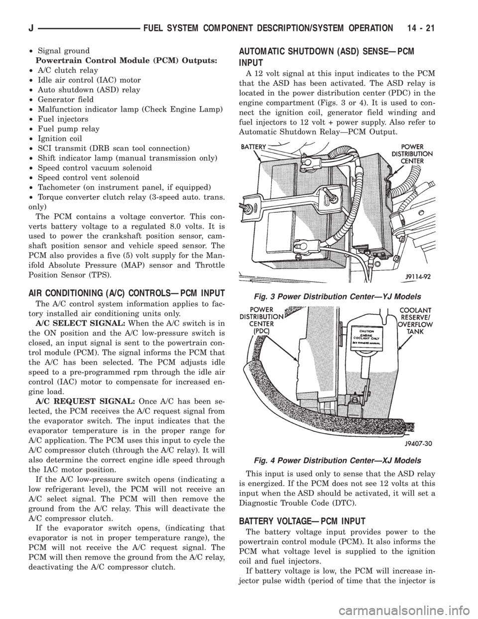
that the ASD has been activated. The ASD relay is
located in the power distribution center (PDC) in the
engine compartment (Figs. 3 or 4). It is used to con-
nect the ignition coil, generator field winding and
fuel injectors to 12 volt + power supply. Also refer to
Automatic Shutdown RelayÐPCM Output.
This input is used only to sense that the ASD relay
is energized. If the PCM does not see 12 volts at this
input when the ASD should be activated, it will set a
Diagnostic Trouble Code (DTC).
BATTERY VOLTAGEÐPCM INPUT
The battery voltage input provides power to the
powertrain control module (PCM). It also informs the
PCM what voltage level is supplied to the ignition
coil and fuel injectors.
If battery voltage is low, the PCM will increase in-
jector pulse width (period of time that the injector is
Fig. 3 Power Distribution CenterÐYJ Models
Fig. 4 Power Distribution CenterÐXJ Models
JFUEL SYSTEM COMPONENT DESCRIPTION/SYSTEM OPERATION 14 - 21
Page 1237 of 2198
energized). This is done to compensate for the re-
duced flow through injector caused by the lowered
voltage.
BRAKE SWITCHÐPCM INPUT
When the brake light switch is activated, the pow-
ertrain control module (PCM) receives an input indi-
cating that the brakes are being applied. After
receiving this input, the PCM maintains idle speed to
a scheduled rpm through control of the idle air con-
trol (IAC) motor. The brake switch input is also used
to operate the speed control system.
CAMSHAFT POSITION SENSORÐPCM INPUT
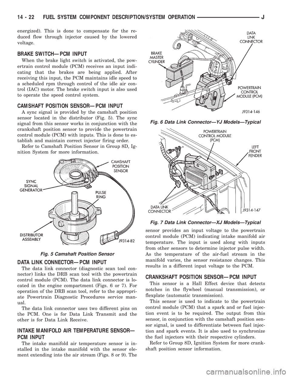
A sync signal is provided by the camshaft position
sensor located in the distributor (Fig. 5). The sync
signal from this sensor works in conjunction with the
crankshaft position sensor to provide the powertrain
control module (PCM) with inputs. This is done to es-
tablish and maintain correct injector firing order.
Refer to Camshaft Position Sensor in Group 8D, Ig-
nition System for more information.
DATA LINK CONNECTORÐPCM INPUT
The data link connector (diagnostic scan tool con-
nector) links the DRB scan tool with the powertrain
control module (PCM). The data link connector is lo-
cated in the engine compartment (Figs. 6 or 7). For
operation of the DRB scan tool, refer to the appropri-
ate Powertrain Diagnostic Procedures service man-
ual.
The data link connector uses two different pins on
the PCM. One is for Data Link Transmit and the
other is for Data Link Receive.
INTAKE MANIFOLD AIR TEMPERATURE SENSORÐ
PCM INPUT
The intake manifold air temperature sensor is in-
stalled in the intake manifold with the sensor ele-
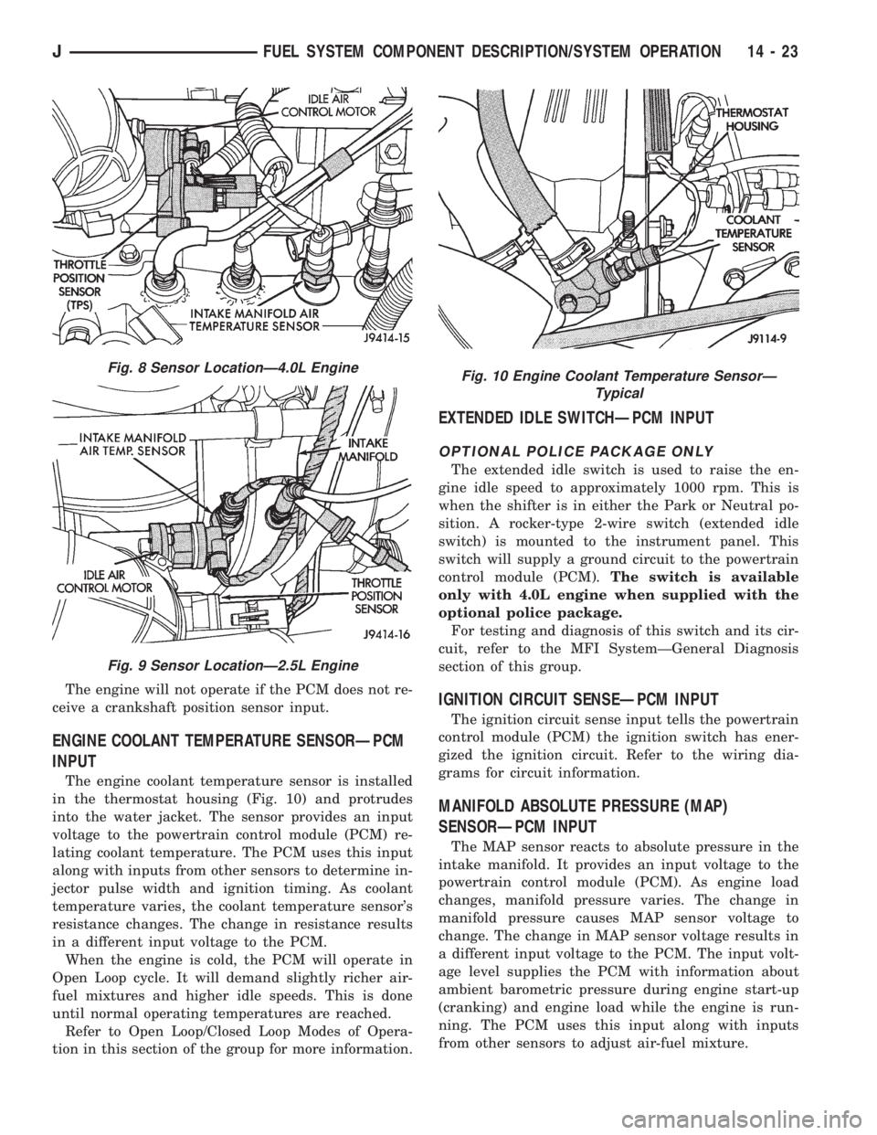
ment extending into the air stream (Figs. 8 or 9). Thesensor provides an input voltage to the powertrain
control module (PCM) indicating intake manifold air
temperature. The input is used along with inputs
from other sensors to determine injector pulse width.
As the temperature of the air-fuel stream in the
manifold varies, the sensor resistance changes. This
results in a different input voltage to the PCM.
CRANKSHAFT POSITION SENSORÐPCM INPUT
This sensor is a Hall Effect device that detects
notches in the flywheel (manual transmission), or
flexplate (automatic transmission).
This sensor is used to indicate to the powertrain
control module (PCM) that a spark and or fuel injec-
tion event is to be required. The output from this
sensor, in conjunction with the camshaft position sen-
sor signal, is used to differentiate between fuel injec-
tion and spark events. It is also used to synchronize
the fuel injectors with their respective cylinders.
Refer to Group 8D, Ignition System for more crank-
shaft position sensor information.
Fig. 5 Camshaft Position Sensor
Fig. 6 Data Link ConnectorÐYJ ModelsÐTypical
Fig. 7 Data Link ConnectorÐXJ ModelsÐTypical
14 - 22 FUEL SYSTEM COMPONENT DESCRIPTION/SYSTEM OPERATIONJ
Page 1238 of 2198
The engine will not operate if the PCM does not re-
ceive a crankshaft position sensor input.
ENGINE COOLANT TEMPERATURE SENSORÐPCM
INPUT
The engine coolant temperature sensor is installed
in the thermostat housing (Fig. 10) and protrudes
into the water jacket. The sensor provides an input
voltage to the powertrain control module (PCM) re-
lating coolant temperature. The PCM uses this input
along with inputs from other sensors to determine in-
jector pulse width and ignition timing. As coolant
temperature varies, the coolant temperature sensor's
resistance changes. The change in resistance results
in a different input voltage to the PCM.
When the engine is cold, the PCM will operate in
Open Loop cycle. It will demand slightly richer air-
fuel mixtures and higher idle speeds. This is done
until normal operating temperatures are reached.
Refer to Open Loop/Closed Loop Modes of Opera-
tion in this section of the group for more information.
EXTENDED IDLE SWITCHÐPCM INPUT
OPTIONAL POLICE PACKAGE ONLY
The extended idle switch is used to raise the en-
gine idle speed to approximately 1000 rpm. This is
when the shifter is in either the Park or Neutral po-
sition. A rocker-type 2-wire switch (extended idle
switch) is mounted to the instrument panel. This
switch will supply a ground circuit to the powertrain
control module (PCM).The switch is available
only with 4.0L engine when supplied with the
optional police package.
For testing and diagnosis of this switch and its cir-
cuit, refer to the MFI SystemÐGeneral Diagnosis
section of this group.
IGNITION CIRCUIT SENSEÐPCM INPUT
The ignition circuit sense input tells the powertrain
control module (PCM) the ignition switch has ener-
gized the ignition circuit. Refer to the wiring dia-
grams for circuit information.
MANIFOLD ABSOLUTE PRESSURE (MAP)
SENSORÐPCM INPUT
The MAP sensor reacts to absolute pressure in the
intake manifold. It provides an input voltage to the
powertrain control module (PCM). As engine load
changes, manifold pressure varies. The change in
manifold pressure causes MAP sensor voltage to
change. The change in MAP sensor voltage results in
a different input voltage to the PCM. The input volt-
age level supplies the PCM with information about
ambient barometric pressure during engine start-up
(cranking) and engine load while the engine is run-
ning. The PCM uses this input along with inputs
from other sensors to adjust air-fuel mixture.
Fig. 8 Sensor LocationÐ4.0L Engine
Fig. 9 Sensor LocationÐ2.5L Engine
Fig. 10 Engine Coolant Temperature SensorÐ
Typical
JFUEL SYSTEM COMPONENT DESCRIPTION/SYSTEM OPERATION 14 - 23
Page 1239 of 2198
The MAP sensor is mounted on the dash panel.
The sensor is connected to the throttle body with a
vacuum hose and to the PCM electrically.
OXYGEN (O2S) SENSORÐPCM INPUT
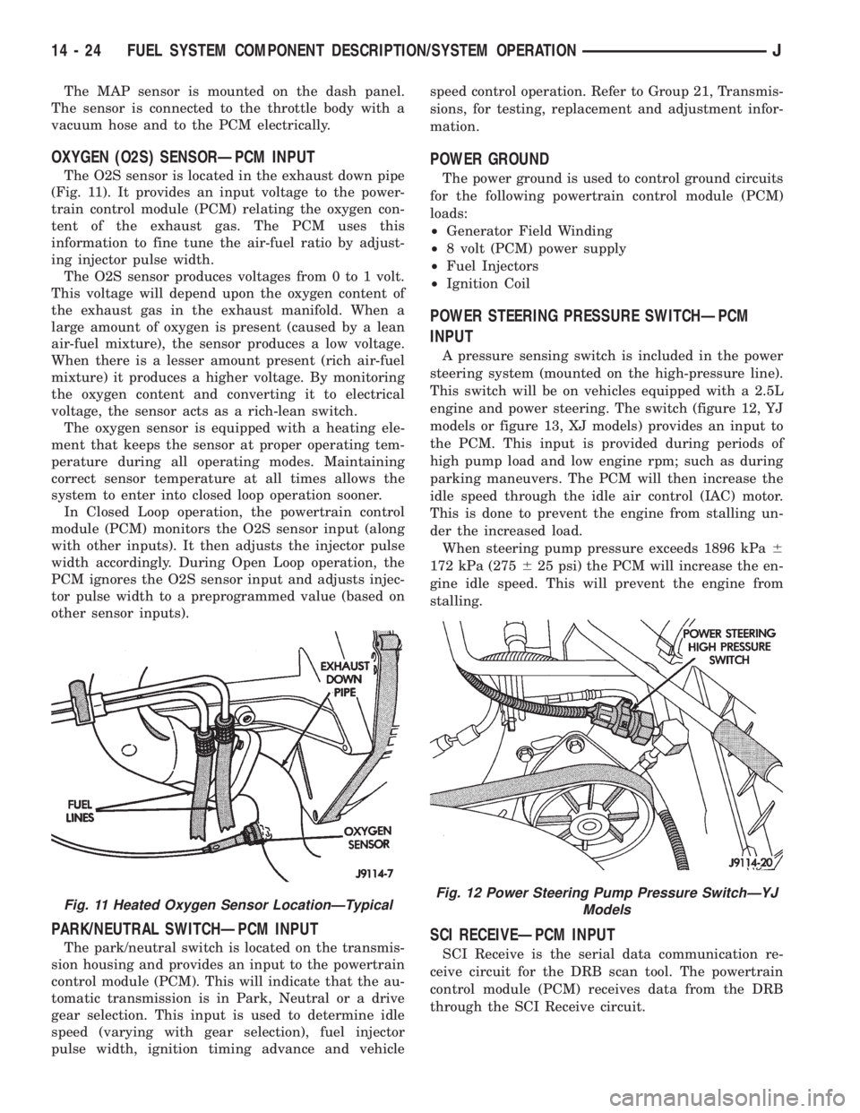
The O2S sensor is located in the exhaust down pipe
(Fig. 11). It provides an input voltage to the power-
train control module (PCM) relating the oxygen con-
tent of the exhaust gas. The PCM uses this
information to fine tune the air-fuel ratio by adjust-
ing injector pulse width.
The O2S sensor produces voltages from 0 to 1 volt.
This voltage will depend upon the oxygen content of
the exhaust gas in the exhaust manifold. When a
large amount of oxygen is present (caused by a lean
air-fuel mixture), the sensor produces a low voltage.
When there is a lesser amount present (rich air-fuel
mixture) it produces a higher voltage. By monitoring
the oxygen content and converting it to electrical
voltage, the sensor acts as a rich-lean switch.
The oxygen sensor is equipped with a heating ele-
ment that keeps the sensor at proper operating tem-
perature during all operating modes. Maintaining
correct sensor temperature at all times allows the
system to enter into closed loop operation sooner.
In Closed Loop operation, the powertrain control
module (PCM) monitors the O2S sensor input (along
with other inputs). It then adjusts the injector pulse
width accordingly. During Open Loop operation, the
PCM ignores the O2S sensor input and adjusts injec-
tor pulse width to a preprogrammed value (based on
other sensor inputs).
PARK/NEUTRAL SWITCHÐPCM INPUT
The park/neutral switch is located on the transmis-
sion housing and provides an input to the powertrain
control module (PCM). This will indicate that the au-
tomatic transmission is in Park, Neutral or a drive
gear selection. This input is used to determine idle
speed (varying with gear selection), fuel injector
pulse width, ignition timing advance and vehiclespeed control operation. Refer to Group 21, Transmis-
sions, for testing, replacement and adjustment infor-
mation.
POWER GROUND
The power ground is used to control ground circuits
for the following powertrain control module (PCM)
loads:
²Generator Field Winding
²8 volt (PCM) power supply
²Fuel Injectors
²Ignition Coil
POWER STEERING PRESSURE SWITCHÐPCM
INPUT
A pressure sensing switch is included in the power
steering system (mounted on the high-pressure line).
This switch will be on vehicles equipped with a 2.5L
engine and power steering. The switch (figure 12, YJ
models or figure 13, XJ models) provides an input to
the PCM. This input is provided during periods of
high pump load and low engine rpm; such as during
parking maneuvers. The PCM will then increase the
idle speed through the idle air control (IAC) motor.
This is done to prevent the engine from stalling un-
der the increased load.
When steering pump pressure exceeds 1896 kPa6
172 kPa (275625 psi) the PCM will increase the en-
gine idle speed. This will prevent the engine from
stalling.
SCI RECEIVEÐPCM INPUT
SCI Receive is the serial data communication re-
ceive circuit for the DRB scan tool. The powertrain
control module (PCM) receives data from the DRB
through the SCI Receive circuit.
Fig. 11 Heated Oxygen Sensor LocationÐTypicalFig. 12 Power Steering Pump Pressure SwitchÐYJ
Models
14 - 24 FUEL SYSTEM COMPONENT DESCRIPTION/SYSTEM OPERATIONJ
Page 1242 of 2198
DATA LINK CONNECTORÐPCM OUTPUT
Refer to the previous paragraphs on Data Link
ConnectorÐPCM Input for information.
EMR LAMPÐPCM OUTPUT
The EMR (SRI) lamp is not used for the 1995
model year.
FUEL PUMP RELAYÐPCM OUTPUT
The PCM energizes the fuel pump and the oxygen
sensor (O2S) heating element through the fuel pump
relay. Battery voltage is applied to the relay from the
ignition switch. The relay is energized when a
ground is provided by the PCM. Refer to Automatic
Shutdown Relay for additional information.
FUEL INJECTORSÐPCM OUTPUT
Six individual fuel injectors are used with the 4.0L
6-cylinder engine. Four individual fuel injectors are
used with the 2.5L 4-cylinder engine. The injectors
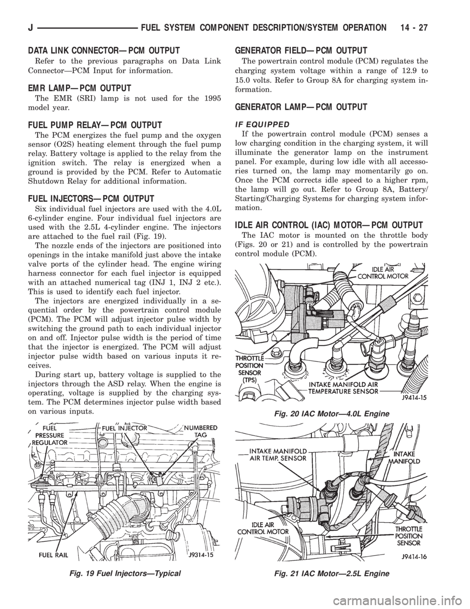
are attached to the fuel rail (Fig. 19).
The nozzle ends of the injectors are positioned into
openings in the intake manifold just above the intake
valve ports of the cylinder head. The engine wiring
harness connector for each fuel injector is equipped
with an attached numerical tag (INJ 1, INJ 2 etc.).
This is used to identify each fuel injector.
The injectors are energized individually in a se-
quential order by the powertrain control module
(PCM). The PCM will adjust injector pulse width by
switching the ground path to each individual injector
on and off. Injector pulse width is the period of time
that the injector is energized. The PCM will adjust
injector pulse width based on various inputs it re-
ceives.
During start up, battery voltage is supplied to the
injectors through the ASD relay. When the engine is
operating, voltage is supplied by the charging sys-
tem. The PCM determines injector pulse width based
on various inputs.
GENERATOR FIELDÐPCM OUTPUT
The powertrain control module (PCM) regulates the
charging system voltage within a range of 12.9 to
15.0 volts. Refer to Group 8A for charging system in-
formation.
GENERATOR LAMPÐPCM OUTPUT
IF EQUIPPED
If the powertrain control module (PCM) senses a
low charging condition in the charging system, it will
illuminate the generator lamp on the instrument
panel. For example, during low idle with all accesso-
ries turned on, the lamp may momentarily go on.
Once the PCM corrects idle speed to a higher rpm,
the lamp will go out. Refer to Group 8A, Battery/
Starting/Charging Systems for charging system infor-
mation.
IDLE AIR CONTROL (IAC) MOTORÐPCM OUTPUT
The IAC motor is mounted on the throttle body
(Figs. 20 or 21) and is controlled by the powertrain
control module (PCM).
Fig. 19 Fuel InjectorsÐTypical
Fig. 20 IAC MotorÐ4.0L Engine
Fig. 21 IAC MotorÐ2.5L Engine
JFUEL SYSTEM COMPONENT DESCRIPTION/SYSTEM OPERATION 14 - 27
Page 1244 of 2198
coolant temperature drops to 98ÉC (208ÉF). Refer to
Group 7, Cooling Systems for more information.
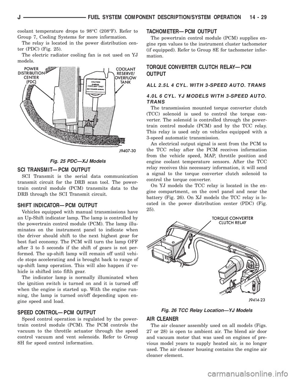
The relay is located in the power distribution cen-
ter (PDC) (Fig. 25).
The electric radiator cooling fan is not used on YJ
models.
SCI TRANSMITÐPCM OUTPUT
SCI Transmit is the serial data communication
transmit circuit for the DRB scan tool. The power-
train control module (PCM) transmits data to the
DRB through the SCI Transmit circuit.
SHIFT INDICATORÐPCM OUTPUT
Vehicles equipped with manual transmissions have
an Up-Shift indicator lamp. The lamp is controlled by
the powertrain control module (PCM). The lamp illu-
minates on the instrument panel to indicate when
the driver should shift to the next highest gear for
best fuel economy. The PCM will turn the lamp OFF
after 3 to 5 seconds if the shift of gears is not per-
formed. The up-shift lamp will remain off until vehi-
cle stops accelerating and is brought back to range of
up-shift lamp operation. This will also happen if ve-
hicle is shifted into fifth gear.
The indicator lamp is normally illuminated when
the ignition switch is turned on and it is turned off
when the engine is started up. With the engine run-
ning, the lamp is turned on/off depending upon en-
gine speed and load.
SPEED CONTROLÐPCM OUTPUT
Speed control operation is regulated by the power-
train control module (PCM). The PCM controls the
vacuum to the throttle actuator through the speed
control vacuum and vent solenoids. Refer to Group
8H for speed control information.
TACHOMETERÐPCM OUTPUT
The powertrain control module (PCM) supplies en-
gine rpm values to the instrument cluster tachometer
(if equipped). Refer to Group 8E for tachometer infor-
mation.
TORQUE CONVERTER CLUTCH RELAYÐPCM
OUTPUT
ALL 2.5L 4 CYL. WITH 3-SPEED AUTO. TRANS
4.0L 6 CYL. YJ MODELS WITH 3-SPEED AUTO.
TRANS
The transmission mounted torque converter clutch
(TCC) solenoid is used to control the torque con-
verter. The solenoid is controlled through the power-
train control module (PCM) and by the TCC relay.
This relay is used only on vehicles equipped with a
3-speed automatic transmission.
An electrical output signal is sent from the PCM to
the TCC relay after the PCM receives information
from the vehicle speed, MAP, throttle position and
engine coolant temperature sensors. After the TCC
relay receives this necessary information, it will send
a signal to the torque converter clutch solenoid to
control the torque converter.
On YJ models the TCC relay is located in the en-
gine compartment, on the cowl panel and near the
battery (Fig. 26). On XJ models the TCC relay is lo-
cated in the power distribution center (PDC) (Fig.
25).
AIR CLEANER
The air cleaner assembly used on all models (Figs.
27 or 28) is open to ambient air. The blend air door
and vacuum motor that was used on engines of pre-
vious model years to supply heated air, is no longer
used. The air cleaner housing contains the engine air
cleaner element.
Fig. 25 PDCÐXJ Models
Fig. 26 TCC Relay LocationÐYJ Models
JFUEL SYSTEM COMPONENT DESCRIPTION/SYSTEM OPERATION 14 - 29
Page 1247 of 2198
²The PCM adjusts ignition timing by increasing
and decreasing spark advance.
²The PCM operates the A/C compressor clutch
through the clutch relay. This happens if A/C has
been selected by the vehicle operator and requested
by the A/C thermostat.
The optional Extended Idle Switch is used to raise
the engine idle speed to approximately 1000 rpm.
This is when the shifter is in either the Park or Neu-
tral position. A rocker-type 2-wire switch (extended
idle switch) is mounted to the instrument panel. This
switch will supply a ground circuit to the powertrain
control module (PCM).The switch is available
only with 4.0L engine when supplied with the
optional police package.
CRUISE MODE
When the engine is at operating temperature, this
is a Closed Loop mode. At cruising speed, the power-
train control module (PCM) receives inputs from:
²Air conditioning select signal (if equipped)
²Air conditioning request signal (if equipped)
²Battery voltage
²Engine coolant temperature sensor
²Crankshaft position sensor
²Intake manifold air temperature sensor
²Manifold absolute pressure (MAP) sensor
²Throttle position sensor (TPS)
²Camshaft position sensor signal (in the distribu-
tor)
²Park/neutral switch (gear indicator signalÐauto.
trans. only)
²Oxygen (O2S) sensor
Based on these inputs, the following occurs:
²Voltage is applied to the fuel injectors with the
PCM. The PCM will then adjust the injector pulse
width by turning the ground circuit to each individ-
ual injector on and off.
²The PCM monitors the O2S sensor input and ad-
justs air-fuel ratio. It also adjusts engine idle speed
through the idle air control (IAC) motor.
²The PCM adjusts ignition timing by turning the
ground path to the coil on and off.
²The PCM operates the A/C compressor clutch
through the clutch relay. This happens if A/C has
been selected by the vehicle operator and requested
by the A/C thermostat.
ACCELERATION MODE
This is an Open Loop mode. The powertrain control
module (PCM) recognizes an abrupt increase in
throttle position or MAP pressure as a demand for
increased engine output and vehicle acceleration. The
PCM increases injector pulse width in response to in-
creased throttle opening.
DECELERATION MODE
When the engine is at operating temperature, this
is an Open Loop mode. During hard deceleration, the
powertrain control module (PCM) receives the follow-
ing inputs.
²Air conditioning select signal (if equipped)
²Air conditioning request signal (if equipped)
²Battery voltage
²Engine coolant temperature sensor
²Crankshaft position sensor
²Intake manifold air temperature sensor
²Manifold absolute pressure (MAP) sensor
²Throttle position sensor (TPS)
²Camshaft position sensor signal (in the distribu-
tor)
²Park/neutral switch (gear indicator signalÐauto.
trans. only)
If the vehicle is under hard deceleration with the
proper rpm and closed throttle conditions, the PCM
will ignore the oxygen sensor input signal. The PCM
will enter a fuel cut-off strategy in which it will not
supply battery voltage to the injectors. If a hard de-
celeration does not exist, the PCM will determine the
proper injector pulse width and continue injection.
Based on the above inputs, the PCM will adjust en-
gine idle speed through the idle air control (IAC) mo-
tor.
The PCM adjusts ignition timing by turning the
ground path to the coil on and off.
The PCM opens the ground circuit to the A/C
clutch relay to disengage the A/C compressor clutch.
This is done until the vehicle is no longer under de-
celeration (if the A/C system is operating).
WIDE OPEN THROTTLE MODE
This is an Open Loop mode. During wide open
throttle operation, the powertrain control module
(PCM) receives the following inputs.
²Battery voltage
²Crankshaft position sensor
²Engine coolant temperature sensor
²Intake manifold air temperature sensor
²Manifold absolute pressure (MAP) sensor
²Throttle position sensor (TPS)
²Camshaft position sensor signal (in the distribu-
tor)
During wide open throttle conditions, the following
occurs:
²Voltage is applied to the fuel injectors with the
powertrain control module (PCM). The PCM will
then control the injection sequence and injector pulse
width by turning the ground circuit to each individ-
ual injector on and off. The PCM ignores the oxygen
sensor input signal and provides a predetermined
amount of additional fuel. This is done by adjusting
injector pulse width.
²The PCM adjusts ignition timing by turning the
ground path to the coil on and off.
14 - 32 FUEL SYSTEM COMPONENT DESCRIPTION/SYSTEM OPERATIONJ
Page 1263 of 2198
EXTENDED IDLE SWITCH TEST
OPTIONAL POLICE PACKAGE ONLY
OPERATION
The extended idle switch is used to raise the en-
gine idle speed to approximately 1000 rpm when the
shifter is in either the Park or Neutral position. A
rocker-type 2-wire switch (extended idle switch) is
mounted to the instrument panel.This switch is
available only with 4.0L engine when supplied
with the optional police package.
TESTING
The extended idle switch will control a ground cir-
cuit going to the powertrain control module (PCM).
When a ground signal (through this switch) has been
received at pin number 10 in the PCM, engine idle
speed will increase.
Bring the engine to normal operating temperature
and turn the extended idle switch to the ON position.
Engine speed should now increase to approximately
1000 rpm when the shifter is in either the Park or
Neutral position. If engine speed does not increase,
apply a good ground to pin number 10 at the PCM
using a small paper clip. Be careful not to damage
the wiring with the paper clip. If the engine speed
now increases, it can be assumed that the PCM is
functioning correctly. Check the instrument panel
mounted switch for a closed ground circuit when in
the ON position. If the engine speed will not increase
after applying a ground to pin number 10, replace
the PCM. Refer to Group 8W, Wiring Diagrams for
circuit and wiring information.
THROTTLE POSITION SENSOR (TPS) TEST
To perform a complete test of the sensor and its cir-
cuitry, refer to DRB scan tool and appropriate Pow-
ertrain Diagnostics Procedures manual. To test the
sensor only, refer to the following:
The throttle position sensor (TPS) can be tested
with a digital voltmeter. The center terminal of the
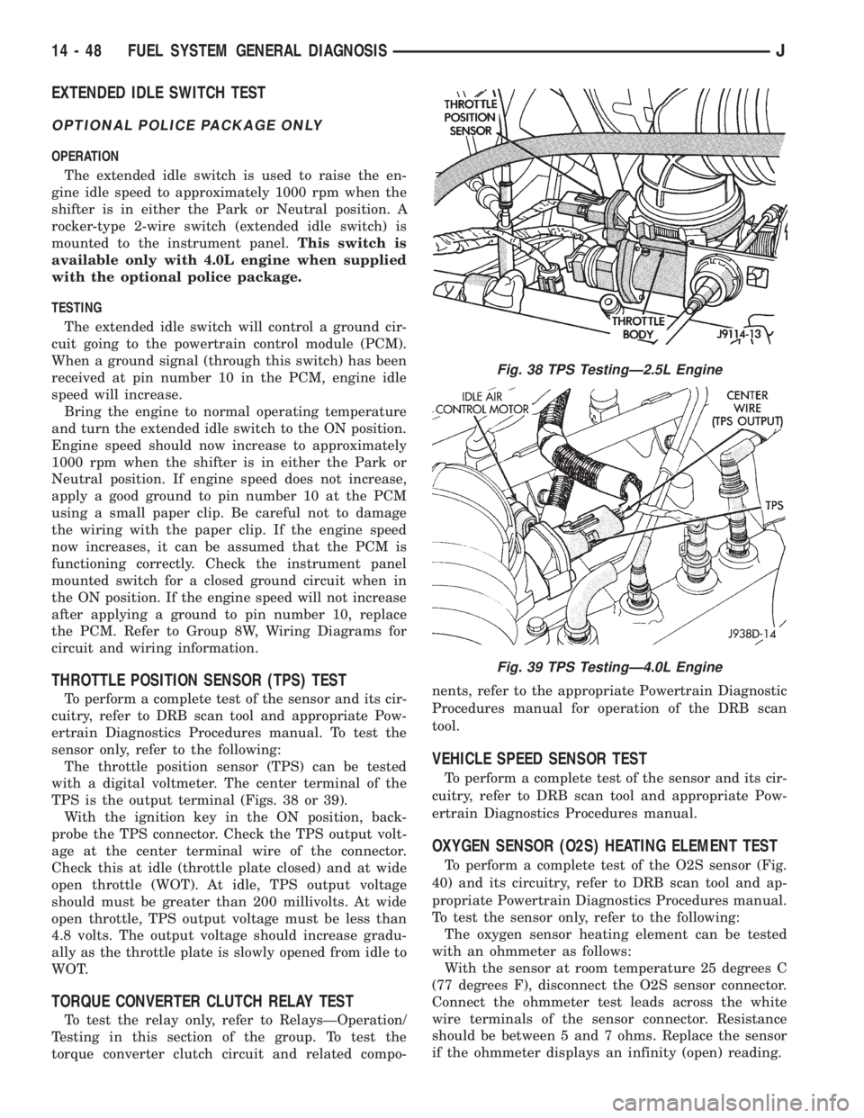
TPS is the output terminal (Figs. 38 or 39).
With the ignition key in the ON position, back-
probe the TPS connector. Check the TPS output volt-
age at the center terminal wire of the connector.
Check this at idle (throttle plate closed) and at wide
open throttle (WOT). At idle, TPS output voltage
should must be greater than 200 millivolts. At wide
open throttle, TPS output voltage must be less than
4.8 volts. The output voltage should increase gradu-
ally as the throttle plate is slowly opened from idle to
WOT.
TORQUE CONVERTER CLUTCH RELAY TEST
To test the relay only, refer to RelaysÐOperation/
Testing in this section of the group. To test the
torque converter clutch circuit and related compo-nents, refer to the appropriate Powertrain Diagnostic
Procedures manual for operation of the DRB scan
tool.
VEHICLE SPEED SENSOR TEST
To perform a complete test of the sensor and its cir-
cuitry, refer to DRB scan tool and appropriate Pow-
ertrain Diagnostics Procedures manual.
OXYGEN SENSOR (O2S) HEATING ELEMENT TEST
To perform a complete test of the O2S sensor (Fig.
40) and its circuitry, refer to DRB scan tool and ap-
propriate Powertrain Diagnostics Procedures manual.
To test the sensor only, refer to the following:
The oxygen sensor heating element can be tested
with an ohmmeter as follows:
With the sensor at room temperature 25 degrees C
(77 degrees F), disconnect the O2S sensor connector.
Connect the ohmmeter test leads across the white
wire terminals of the sensor connector. Resistance
should be between 5 and 7 ohms. Replace the sensor
if the ohmmeter displays an infinity (open) reading.
Fig. 38 TPS TestingÐ2.5L Engine
Fig. 39 TPS TestingÐ4.0L Engine
14 - 48 FUEL SYSTEM GENERAL DIAGNOSISJ