1995 JEEP CHEROKEE ECO mode
[x] Cancel search: ECO modePage 251 of 2198
(4) When checking for vacuum leaks.
WARNING: IF VEHICLE HAS BEEN RUN RECENTLY,
WAIT AT LEAST 15 MINUTES BEFORE REMOVING
RADIATOR CAP. WITH A RAG, SQUEEZE RADIATOR
UPPER HOSE TO CHECK IF SYSTEM IS UNDER
PRESSURE. PLACE A RAG OVER THE CAP AND
WITHOUT PUSHING DOWN, ROTATE CAP
COUNTER-CLOCKWISE TO THE FIRST STOP. AL-
LOW FLUID TO ESCAPE THROUGH OVERFLOW
HOSE INTO COOLANT RESERVE/OVERFLOW
TANK. SQUEEZE RADIATOR UPPER HOSE TO DE-
TERMINE WHEN PRESSURE HAS BEEN RE-
LEASED. WHEN COOLANT AND STEAM STOP
BEING PUSHED INTO TANK AND SYSTEM PRES-
SURE DROPS, REMOVE RADIATOR CAP COM-
PLETELY.
PRESSURE TESTING RADIATOR CAPS
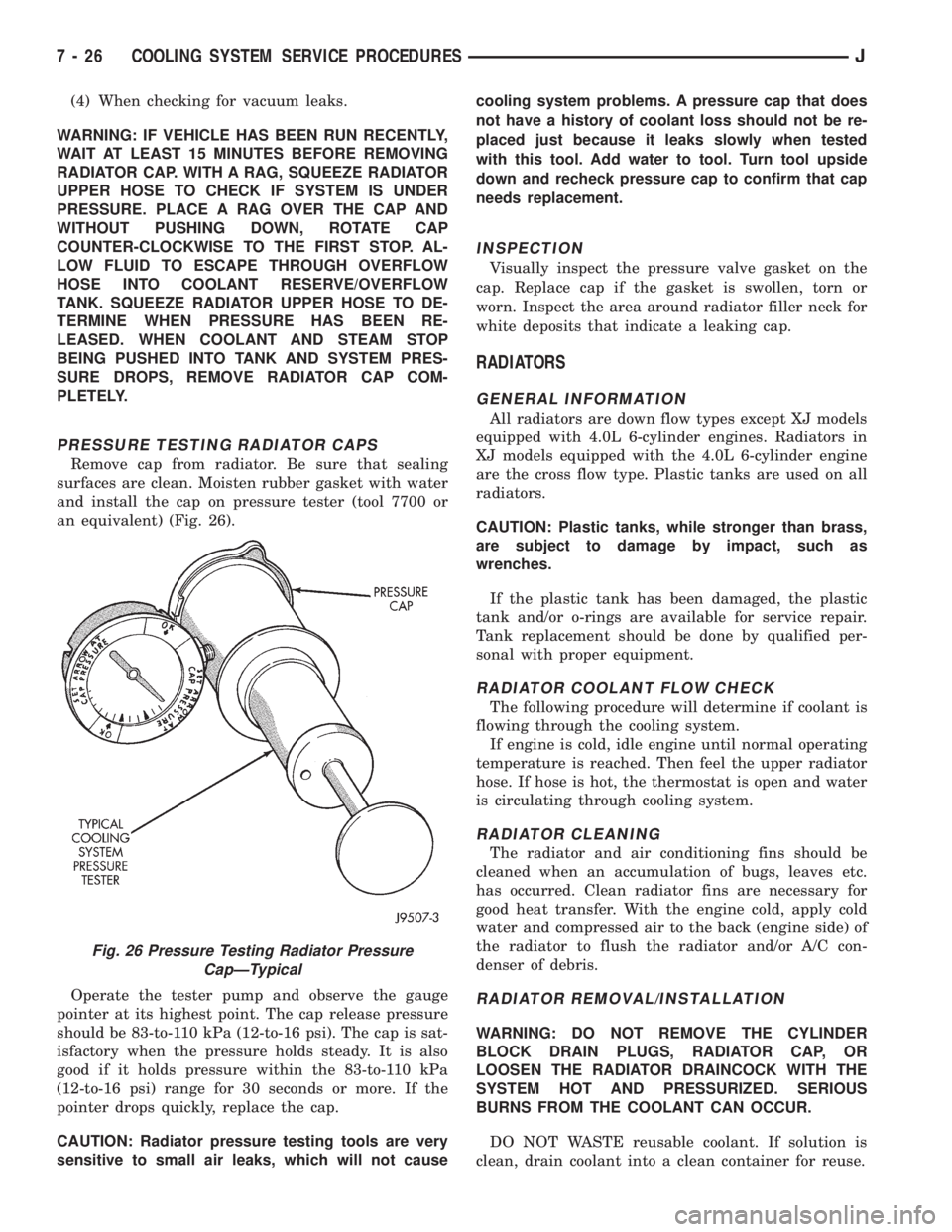
Remove cap from radiator. Be sure that sealing
surfaces are clean. Moisten rubber gasket with water
and install the cap on pressure tester (tool 7700 or
an equivalent) (Fig. 26).
Operate the tester pump and observe the gauge
pointer at its highest point. The cap release pressure
should be 83-to-110 kPa (12-to-16 psi). The cap is sat-
isfactory when the pressure holds steady. It is also
good if it holds pressure within the 83-to-110 kPa
(12-to-16 psi) range for 30 seconds or more. If the
pointer drops quickly, replace the cap.
CAUTION: Radiator pressure testing tools are very
sensitive to small air leaks, which will not causecooling system problems. A pressure cap that does
not have a history of coolant loss should not be re-
placed just because it leaks slowly when tested
with this tool. Add water to tool. Turn tool upside
down and recheck pressure cap to confirm that cap
needs replacement.
INSPECTION
Visually inspect the pressure valve gasket on the
cap. Replace cap if the gasket is swollen, torn or
worn. Inspect the area around radiator filler neck for
white deposits that indicate a leaking cap.
RADIATORS
GENERAL INFORMATION
All radiators are down flow types except XJ models
equipped with 4.0L 6-cylinder engines. Radiators in
XJ models equipped with the 4.0L 6-cylinder engine
are the cross flow type. Plastic tanks are used on all
radiators.
CAUTION: Plastic tanks, while stronger than brass,
are subject to damage by impact, such as
wrenches.
If the plastic tank has been damaged, the plastic
tank and/or o-rings are available for service repair.
Tank replacement should be done by qualified per-
sonal with proper equipment.
RADIATOR COOLANT FLOW CHECK
The following procedure will determine if coolant is
flowing through the cooling system.
If engine is cold, idle engine until normal operating
temperature is reached. Then feel the upper radiator
hose. If hose is hot, the thermostat is open and water
is circulating through cooling system.
RADIATOR CLEANING
The radiator and air conditioning fins should be
cleaned when an accumulation of bugs, leaves etc.
has occurred. Clean radiator fins are necessary for
good heat transfer. With the engine cold, apply cold
water and compressed air to the back (engine side) of
the radiator to flush the radiator and/or A/C con-
denser of debris.
RADIATOR REMOVAL/INSTALLATION
WARNING: DO NOT REMOVE THE CYLINDER
BLOCK DRAIN PLUGS, RADIATOR CAP, OR
LOOSEN THE RADIATOR DRAINCOCK WITH THE
SYSTEM HOT AND PRESSURIZED. SERIOUS
BURNS FROM THE COOLANT CAN OCCUR.
DO NOT WASTE reusable coolant. If solution is
clean, drain coolant into a clean container for reuse.
Fig. 26 Pressure Testing Radiator Pressure
CapÐTypical
7 - 26 COOLING SYSTEM SERVICE PROCEDURESJ
Page 261 of 2198
nostic Procedures manual for diagnostic information
and operation of the DRB scan tool.
To test operation of the fan relay only, refer to Re-
laysÐOperation/Testing. This can be found in Group
14, Fuel Systems.
REMOVAL
The auxiliary cooling fan is attached to the radia-
tor upper crossmember behind the radiator.
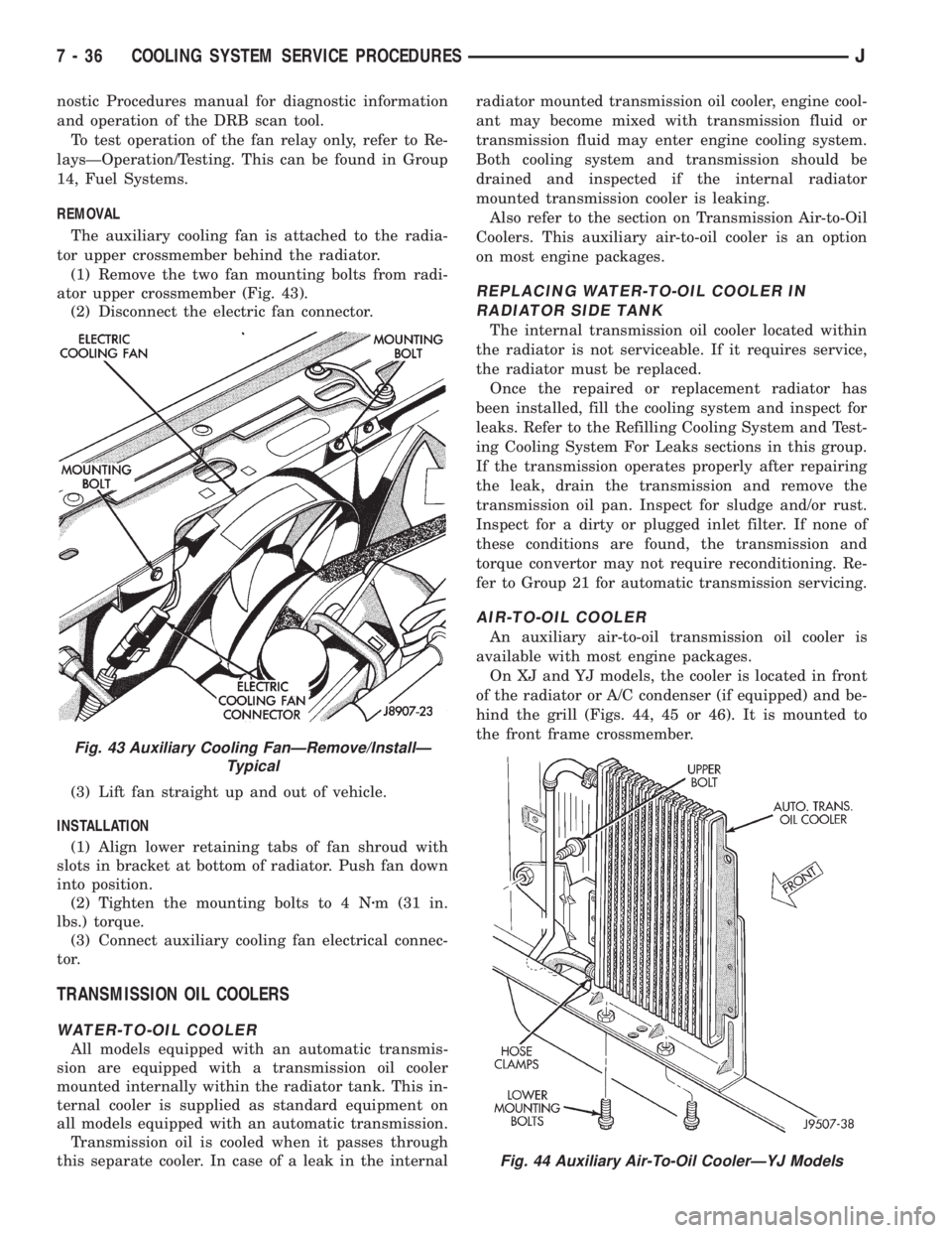
(1) Remove the two fan mounting bolts from radi-
ator upper crossmember (Fig. 43).
(2) Disconnect the electric fan connector.
(3) Lift fan straight up and out of vehicle.
INSTALLATION
(1) Align lower retaining tabs of fan shroud with
slots in bracket at bottom of radiator. Push fan down
into position.
(2) Tighten the mounting bolts to 4 Nzm (31 in.
lbs.) torque.
(3) Connect auxiliary cooling fan electrical connec-
tor.
TRANSMISSION OIL COOLERS
WATER-TO-OIL COOLER
All models equipped with an automatic transmis-
sion are equipped with a transmission oil cooler
mounted internally within the radiator tank. This in-
ternal cooler is supplied as standard equipment on
all models equipped with an automatic transmission.
Transmission oil is cooled when it passes through
this separate cooler. In case of a leak in the internalradiator mounted transmission oil cooler, engine cool-
ant may become mixed with transmission fluid or
transmission fluid may enter engine cooling system.
Both cooling system and transmission should be
drained and inspected if the internal radiator
mounted transmission cooler is leaking.
Also refer to the section on Transmission Air-to-Oil
Coolers. This auxiliary air-to-oil cooler is an option
on most engine packages.
REPLACING WATER-TO-OIL COOLER IN
RADIATOR SIDE TANK
The internal transmission oil cooler located within
the radiator is not serviceable. If it requires service,
the radiator must be replaced.
Once the repaired or replacement radiator has
been installed, fill the cooling system and inspect for
leaks. Refer to the Refilling Cooling System and Test-
ing Cooling System For Leaks sections in this group.
If the transmission operates properly after repairing
the leak, drain the transmission and remove the
transmission oil pan. Inspect for sludge and/or rust.
Inspect for a dirty or plugged inlet filter. If none of
these conditions are found, the transmission and
torque convertor may not require reconditioning. Re-
fer to Group 21 for automatic transmission servicing.
AIR-TO-OIL COOLER
An auxiliary air-to-oil transmission oil cooler is
available with most engine packages.
On XJ and YJ models, the cooler is located in front
of the radiator or A/C condenser (if equipped) and be-
hind the grill (Figs. 44, 45 or 46). It is mounted to
the front frame crossmember.
Fig. 43 Auxiliary Cooling FanÐRemove/InstallÐ
Typical
Fig. 44 Auxiliary Air-To-Oil CoolerÐYJ Models
7 - 36 COOLING SYSTEM SERVICE PROCEDURESJ
Page 288 of 2198
CHARGING SYSTEM
GENERAL INFORMATION
The charging system consists of:
²generator
²voltage regulator circuitry (within PCM)
²ignition switch
²battery
²generator warning lamp or voltmeter (depending
on vehicle equipment)
²wiring harness and connections.
Following is a general description of the major
charging system components. Refer to Group 8W -
Wiring Diagrams for complete circuit descriptions
and diagrams.
The charging system is turned on and off with the
ignition switch. When the ignition switch is turned to
the ON position, battery voltage is applied to the
generator rotor through one of the two field termi-
nals to produce a magnetic field. The generator is
driven by the engine through a serpentine belt and
pulley arrangement.
As the energized rotor begins to rotate within the
generator, the spinning magnetic field induces a cur-
rent into the windings of the stator coil. Once the
generator begins producing sufficient current, it also
provides the current needed to energize the rotor.
The wye (Y) type stator winding connections de-
liver the induced AC current to 3 positive and 3 neg-
ative diodes for rectification. From the diodes,
rectified DC current is delivered to the vehicle elec-
trical system through the generator battery and
ground terminals.
The amount of DC current produced by the gener-
ator is controlled by the generator voltage regulator
(field control) circuitry, contained within the Power-
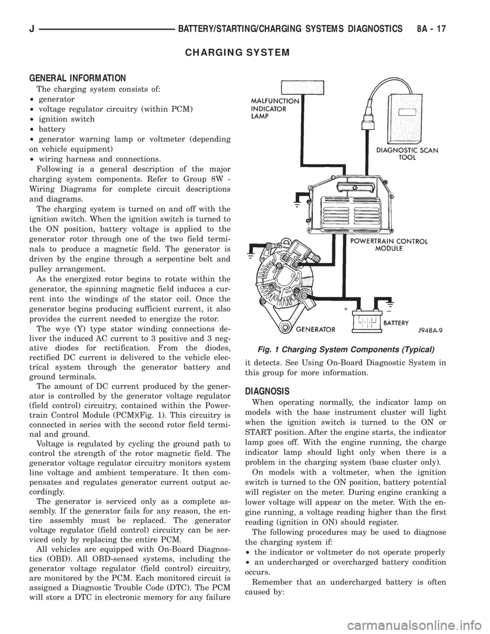
train Control Module (PCM)(Fig. 1). This circuitry is
connected in series with the second rotor field termi-
nal and ground.
Voltage is regulated by cycling the ground path to
control the strength of the rotor magnetic field. The
generator voltage regulator circuitry monitors system
line voltage and ambient temperature. It then com-
pensates and regulates generator current output ac-
cordingly.
The generator is serviced only as a complete as-
sembly. If the generator fails for any reason, the en-
tire assembly must be replaced. The generator
voltage regulator (field control) circuitry can be ser-
viced only by replacing the entire PCM.
All vehicles are equipped with On-Board Diagnos-
tics (OBD). All OBD-sensed systems, including the
generator voltage regulator (field control) circuitry,
are monitored by the PCM. Each monitored circuit is
assigned a Diagnostic Trouble Code (DTC). The PCM
will store a DTC in electronic memory for any failureit detects. See Using On-Board Diagnostic System in
this group for more information.
DIAGNOSIS
When operating normally, the indicator lamp on
models with the base instrument cluster will light
when the ignition switch is turned to the ON or
START position. After the engine starts, the indicator
lamp goes off. With the engine running, the charge
indicator lamp should light only when there is a
problem in the charging system (base cluster only).
On models with a voltmeter, when the ignition
switch is turned to the ON position, battery potential
will register on the meter. During engine cranking a
lower voltage will appear on the meter. With the en-
gine running, a voltage reading higher than the first
reading (ignition in ON) should register.
The following procedures may be used to diagnose
the charging system if:
²the indicator or voltmeter do not operate properly
²an undercharged or overcharged battery condition
occurs.
Remember that an undercharged battery is often
caused by:
Fig. 1 Charging System Components (Typical)
JBATTERY/STARTING/CHARGING SYSTEMS DIAGNOSTICS 8A - 17
Page 304 of 2198
OVERHEAD CONSOLE
CONTENTS
page page
DIAGNOSIS............................. 2
GENERAL INFORMATION.................. 1SERVICE PROCEDURES................... 5
GENERAL INFORMATION
An overhead console featuring an electronic com-
pass and thermometer is an available option for XJ
(Cherokee) models. Following are general descrip-
tions of major components used in the overhead con-
sole. Refer to Group 8W - Wiring Diagrams for
complete circuit descriptions and diagrams.
COMPASS
The compass will display the direction in which the
vehicle is pointed using the eight major compass
headings (Examples: north is N, northeast is NE). It
does not display the headings in actual degrees. The
display is turned on or off using the COMP/TEMP
button to the left of the display.
The self-calibrating compass unit requires no ad-
justing in normal use. The only calibration that may
prove necessary is to drive the vehicle in 3 complete
circles, on level ground, in not less than 48 seconds.
This will reorient the unit to its vehicle.
The unit also will compensate for magnetism the
body of the vehicle may acquire during normal use.
However, avoid placing anything magnetic directly on
the roof of the vehicle. Magnetic mounts for an an-
tenna, a repair order hat or a funeral procession flag
can exceed the compensating ability of the compass
unit if placed on the roof panel. Magnetic bit drivers
used on the fasteners that hold the assembly to the
roof header can also affect compass operation.
If the vehicle roof should become magnetized, the
demagnetizing and calibration procedures may be re-
quired to restore proper operation.
THERMOMETER
The thermometer displays the outside ambient
temperature. The temperature displayed can be
changed from Fahrenheit to Celsius using the US/
METRIC button. The displayed temperature is not
an instant reading of conditions, but an average tem-
perature. It may take the unit several minutes to re-
act to a major temperature change such as driving
out of a heated garage into winter temperatures.
When the ignition switch is turned OFF, the lastdisplayed temperature reading stays in memory.
When the ignition switch is turned ON again, the
thermometer will display the memory temperature
for one minute; then update the display to the cur-
rent average temperature reading within five min-
utes.
READING AND COURTESY LAMPS
All reading and courtesy lamps in the overhead
console are activated by the door jamb switches.
When all doors and the liftgate are closed, the lamps
can be individually activated by depressing the corre-
sponding lens. When a door and/or the liftgate is
open, depressing the lamp lens switches will not turn
the lamps off. Refer to Group 8L - Lamps, for diag-
nosis and service of these lamps.
KEYLESS ENTRY RECEIVER
The overhead console houses the keyless entry re-
ceiver. Refer to Group 8P - Power Locks, for diagno-
sis and service of this component.
REMOTE GARAGE DOOR OPENER STORAGE
A compartment in the overhead console is designed
to hold most remote garage door opener transmitters.
The transmitter is mounted within the compartment
with an adhesive-backed hook and loop fastener
patch. Then one to three pegs are selected and
mounted on a post on the inside of the storage com-
partment door. The pegs may be stacked, if neces-
sary. The peg(s) selected must be long enough to
activate the button of the transmitter each time the
storage compartment door is depressed.
SUNGLASSES STORAGE
A flocked storage compartment for sunglasses is in-
cluded in the overhead console. This compartment
features a push/push-type latch and a viscous damp-
ening system for a fluid opening motion.
JOVERHEAD CONSOLE 8C - 1
Page 305 of 2198
DIAGNOSIS
COMPASS/DISPLAY SELF-DIAGNOSTIC TEST
This self-diagnostic test is used to determine that
the compass and all of its display segments are oper-
ating properly electrically. Initiate the self-diagnostic
test as follows:
(1) With the ignition switch in the OFF position,
simultaneously press and hold the COMP/TEMP but-
ton and the US/METRIC button.
(2) Turn ignition switch to the ON position.
(3) Continue to hold both buttons until the display
performs a walking segment test. In this test all of
the compass points are displayed, along with various
number combinations. These combinations verify that
all display segments are functional. If any segment
should fail to light during the test, the unit is faulty
and requires replacement. To repeat the test, momen-
tarily depress and release the COMP/TEMP button
one time.
(4) Momentarily depress and release the US/MET-
RIC button one time and all segments will light si-
multaneously for about 2 seconds. If any segment
should fail to light during the test, the unit is faulty
and requires replacement. To repeat the test, momen-
tarily depress and release the COMP/TEMP button
one time.
(5) Momentarily depress and release the US/MET-
RIC button one time or turn the ignition switch to
OFF to exit the self-diagnostic mode and return to
normal operation.
If the compass functions, but accuracy is sus-
pect, it may be necessary to perform a variation
adjustment. This procedure allows the unit to
accommodate variations in the earth's mag-
netic field strength based on geographic loca-
tion. See Compass Variation Adjustment, in this
group.
If the compass display has blanked out and
only CAL appears, demagnetizing may be nec-
essary to remove excessive residual magnetic
fields from the vehicle. See Compass Demagne-
tizing, in this group.
THERMOMETER DIAGNOSIS
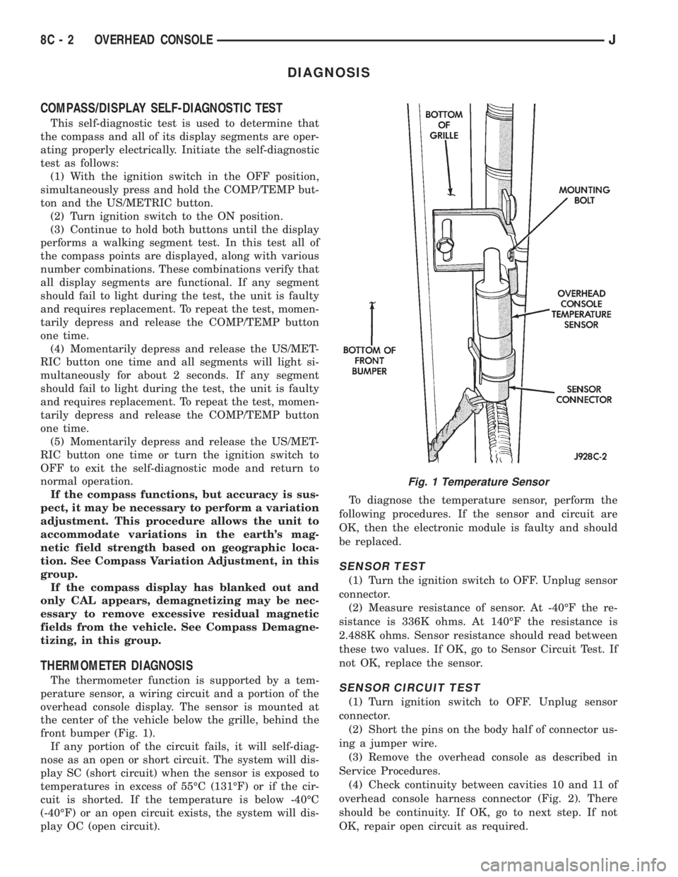
The thermometer function is supported by a tem-
perature sensor, a wiring circuit and a portion of the
overhead console display. The sensor is mounted at
the center of the vehicle below the grille, behind the
front bumper (Fig. 1).
If any portion of the circuit fails, it will self-diag-
nose as an open or short circuit. The system will dis-
play SC (short circuit) when the sensor is exposed to
temperatures in excess of 55ÉC (131ÉF) or if the cir-
cuit is shorted. If the temperature is below -40ÉC
(-40ÉF) or an open circuit exists, the system will dis-
play OC (open circuit).To diagnose the temperature sensor, perform the
following procedures. If the sensor and circuit are
OK, then the electronic module is faulty and should
be replaced.
SENSOR TEST
(1) Turn the ignition switch to OFF. Unplug sensor
connector.
(2) Measure resistance of sensor. At -40ÉF the re-
sistance is 336K ohms. At 140ÉF the resistance is
2.488K ohms. Sensor resistance should read between
these two values. If OK, go to Sensor Circuit Test. If
not OK, replace the sensor.
SENSOR CIRCUIT TEST
(1) Turn ignition switch to OFF. Unplug sensor
connector.
(2) Short the pins on the body half of connector us-
ing a jumper wire.
(3) Remove the overhead console as described in
Service Procedures.
(4) Check continuity between cavities 10 and 11 of
overhead console harness connector (Fig. 2). There
should be continuity. If OK, go to next step. If not
OK, repair open circuit as required.
Fig. 1 Temperature Sensor
8C - 2 OVERHEAD CONSOLEJ
Page 312 of 2198
IGNITION SYSTEMS
CONTENTS
page page
COMPONENT IDENTIFICATION/SYSTEM
OPERATION........................... 1
COMPONENT REMOVAL/INSTALLATION...... 17
DIAGNOSTICS/SERVICE PROCEDURES....... 6IGNITION SWITCHÐXJ MODELS........... 26
IGNITION SWITCHÐYJ MODELS........... 29
SPECIFICATIONS........................ 32
COMPONENT IDENTIFICATION/SYSTEM OPERATION
INDEX
page page
Automatic Shutdown (ASD) Relay.............. 1
Camshaft Position Sensor.................... 2
Crankshaft Position Sensor................... 3
Distributors............................... 4
Engine Coolant Temperature Sensor............ 5
General Information........................ 1Ignition Coil.............................. 4
Intake Manifold Air Temperature Sensor.......... 5
Manifold Absolute Pressure (MAP) Sensor........ 5
Oxygen (O2S) Sensor....................... 5
Powertrain Control Module (PCM).............. 5
Throttle Position Sensor..................... 5
GENERAL INFORMATION
Throughout this group, references are made to par-
ticular vehicle models by alphabetical designation
(XJ or YJ) or by the particular vehicle nameplate. A
chart showing a breakdown of alphabetical designa-
tions is included in the Introduction group at the be-
ginning of this manual.
This section of the group, Component Identifica-
tion/System Operation, will discuss ignition system
operation and will identify ignition system compo-
nents.
For diagnostic procedures and adjustments, refer to
the Diagnostics/Service Procedures section of this
group.
For removal and installation of ignition system
components, refer to the Component Removal/Instal-
lation section of this group.
For other useful information, refer to On-Board Di-
agnostics in the General Diagnosis sections of Group
14, Fuel System in this manual.
For operation of the DRB Scan Tool, refer to the
appropriate Powertrain Diagnostic Procedures ser-
vice manual.
An Ignition specifications section is included at the
end of this group. A general Maintenance Schedule
(mileage intervals) for ignition related items can be
found in Group 0, Lubrication and Maintenance. This
schedule can also be found in the Owners Manual.
IGNITION SYSTEMS
A multi-port, fuel injected engine is used on all
models. The ignition system is controlled by the pow-
ertrain control module (PCM) on all engines. The
PCM was formerly referred to as the SBEC or engine
controller.
The ignition system consists of:
²Spark plugs
²Ignition coil
²Secondary ignition cables
²Distributor (contains rotor and camshaft position
sensor)
²Powertrain control module (PCM)
²Crankshaft position sensor
AUTOMATIC SHUTDOWN (ASD) RELAY
The automatic shutdown (ASD) relay is located in
the power distribution center (PDC) near the battery
(Fig. 1 or 2). As one of its functions, it will supply
battery voltage to the ignition coil.
The ground circuit for the ASD relay is controlled
by the powertrain control module (PCM). This is
done through pin/cavity number 51 of the PCM 60-
way connector. The PCM then regulates ASD relay
operation by switching this ground circuit on-and-off.
Also refer to Ignition Coil for additional informa-
tion.
JIGNITION SYSTEMS 8D - 1
Page 322 of 2198
(4) Crank the engine for 5 seconds while monitor-
ing the voltage at the coil positive terminal:
²If the voltage remains near zero during the entire
period of cranking, refer to On-Board Diagnostics in
Group 14, Fuel Systems. Check the powertrain con-
trol module (PCM) and auto shutdown relay.
²If voltage is at or near battery voltage and drops
to zero after 1-2 seconds of cranking, check the cam-
shaft position sensor-to-PCM circuit. Refer to On-
Board Diagnostics in Group 14, Fuel Systems.
²If voltage remains at or near battery voltage dur-
ing the entire 5 seconds, turn the key off. Remove
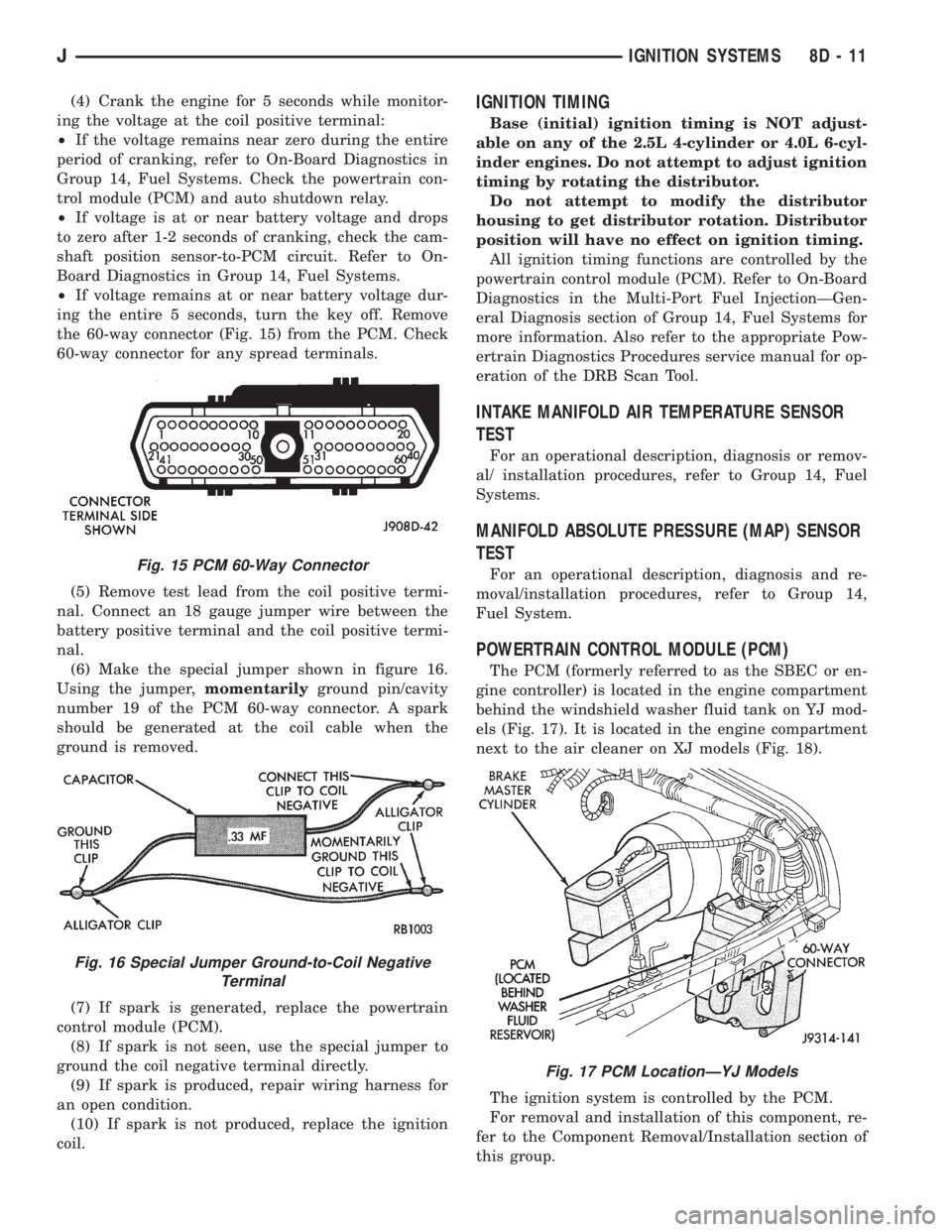
the 60-way connector (Fig. 15) from the PCM. Check
60-way connector for any spread terminals.
(5) Remove test lead from the coil positive termi-
nal. Connect an 18 gauge jumper wire between the
battery positive terminal and the coil positive termi-
nal.
(6) Make the special jumper shown in figure 16.
Using the jumper,momentarilyground pin/cavity
number 19 of the PCM 60-way connector. A spark
should be generated at the coil cable when the
ground is removed.
(7) If spark is generated, replace the powertrain
control module (PCM).
(8) If spark is not seen, use the special jumper to
ground the coil negative terminal directly.
(9) If spark is produced, repair wiring harness for
an open condition.
(10) If spark is not produced, replace the ignition
coil.IGNITION TIMING
Base (initial) ignition timing is NOT adjust-
able on any of the 2.5L 4-cylinder or 4.0L 6-cyl-
inder engines. Do not attempt to adjust ignition
timing by rotating the distributor.
Do not attempt to modify the distributor
housing to get distributor rotation. Distributor
position will have no effect on ignition timing.
All ignition timing functions are controlled by the
powertrain control module (PCM). Refer to On-Board
Diagnostics in the Multi-Port Fuel InjectionÐGen-
eral Diagnosis section of Group 14, Fuel Systems for
more information. Also refer to the appropriate Pow-
ertrain Diagnostics Procedures service manual for op-
eration of the DRB Scan Tool.
INTAKE MANIFOLD AIR TEMPERATURE SENSOR
TEST
For an operational description, diagnosis or remov-
al/ installation procedures, refer to Group 14, Fuel
Systems.
MANIFOLD ABSOLUTE PRESSURE (MAP) SENSOR
TEST
For an operational description, diagnosis and re-
moval/installation procedures, refer to Group 14,
Fuel System.
POWERTRAIN CONTROL MODULE (PCM)
The PCM (formerly referred to as the SBEC or en-
gine controller) is located in the engine compartment
behind the windshield washer fluid tank on YJ mod-
els (Fig. 17). It is located in the engine compartment
next to the air cleaner on XJ models (Fig. 18).
The ignition system is controlled by the PCM.
For removal and installation of this component, re-
fer to the Component Removal/Installation section of
this group.
Fig. 15 PCM 60-Way Connector
Fig. 16 Special Jumper Ground-to-Coil Negative
Terminal
Fig. 17 PCM LocationÐYJ Models
JIGNITION SYSTEMS 8D - 11
Page 323 of 2198
For diagnostics, refer to the appropriate Powertrain
Diagnostic Procedures service manual for operation
of the DRB scan tool.
SPARK PLUGS
For spark plug removal, cleaning, gap adjustment
and installation, refer to the Component Removal/In-
stallation section of this group.
Faulty carbon and/or gas fouled plugs generally
cause hard starting, but they will clean up at higher
engine speeds. Faulty plugs can be identified in a
number of ways: poor fuel economy, power loss, de-
crease in engine speed, hard starting and, in general,
poor engine performance.
Remove the spark plugs and examine them for
burned electrodes and fouled, cracked or broken por-
celain insulators. For identification, keep plugs ar-
ranged in the order in which they were removed from
the engine. An isolated plug displaying an abnormal
condition indicates that a problem exists in the cor-
responding cylinder. Replace spark plugs at the inter-
vals recommended in the maintenance chart in
Group 0, Lubrication and Maintenance.
Spark plugs that have low mileage may be cleaned
and reused if not otherwise defective. Refer to the
following Spark Plug Condition section of this group.
CONDITION
NORMAL OPERATING
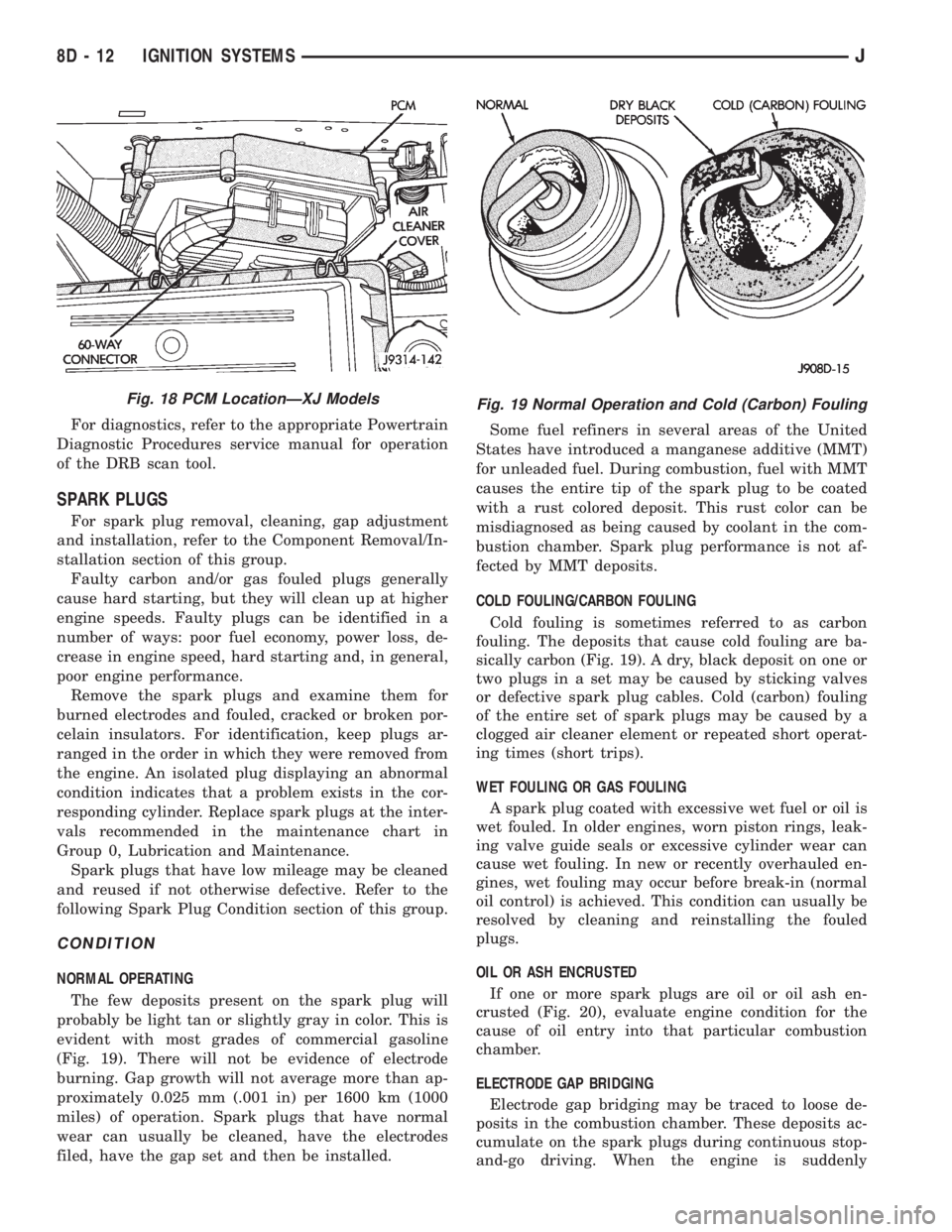
The few deposits present on the spark plug will
probably be light tan or slightly gray in color. This is
evident with most grades of commercial gasoline
(Fig. 19). There will not be evidence of electrode
burning. Gap growth will not average more than ap-
proximately 0.025 mm (.001 in) per 1600 km (1000
miles) of operation. Spark plugs that have normal
wear can usually be cleaned, have the electrodes
filed, have the gap set and then be installed.Some fuel refiners in several areas of the United
States have introduced a manganese additive (MMT)
for unleaded fuel. During combustion, fuel with MMT
causes the entire tip of the spark plug to be coated
with a rust colored deposit. This rust color can be
misdiagnosed as being caused by coolant in the com-
bustion chamber. Spark plug performance is not af-
fected by MMT deposits.
COLD FOULING/CARBON FOULING
Cold fouling is sometimes referred to as carbon
fouling. The deposits that cause cold fouling are ba-
sically carbon (Fig. 19). A dry, black deposit on one or
two plugs in a set may be caused by sticking valves
or defective spark plug cables. Cold (carbon) fouling
of the entire set of spark plugs may be caused by a
clogged air cleaner element or repeated short operat-
ing times (short trips).
WET FOULING OR GAS FOULING
A spark plug coated with excessive wet fuel or oil is
wet fouled. In older engines, worn piston rings, leak-
ing valve guide seals or excessive cylinder wear can
cause wet fouling. In new or recently overhauled en-
gines, wet fouling may occur before break-in (normal
oil control) is achieved. This condition can usually be
resolved by cleaning and reinstalling the fouled
plugs.
OIL OR ASH ENCRUSTED
If one or more spark plugs are oil or oil ash en-
crusted (Fig. 20), evaluate engine condition for the
cause of oil entry into that particular combustion
chamber.
ELECTRODE GAP BRIDGING
Electrode gap bridging may be traced to loose de-
posits in the combustion chamber. These deposits ac-
cumulate on the spark plugs during continuous stop-
and-go driving. When the engine is suddenly
Fig. 18 PCM LocationÐXJ ModelsFig. 19 Normal Operation and Cold (Carbon) Fouling
8D - 12 IGNITION SYSTEMSJ